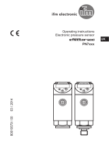
IFM PN7300 Operating instructions

Category
Measuring, testing & control
Type
Operating instructions

This manual is also suitable for

Operating instructions
Pressure sensor
PN73xx
UK
706183 / 00 04 / 2012
2
Contents
1 Preliminary note ���������������������������������������������������������������������������������������������������3
1�1 Symbols used ������������������������������������������������������������������������������������������������3
2 Safety instructions �����������������������������������������������������������������������������������������������3
3 Functions and features ����������������������������������������������������������������������������������������4
4 Function ���������������������������������������������������������������������������������������������������������������5
4�1 Communication, parameter setting, evaluation ���������������������������������������������5
4�2 Switching function ������������������������������������������������������������������������������������������5
4�3 Diagnostic function ����������������������������������������������������������������������������������������6
5 Installation������������������������������������������������������������������������������������������������������������6
6 Electrical connection ��������������������������������������������������������������������������������������������7
7 Operating and display elements �������������������������������������������������������������������������8
8 Menu ��������������������������������������������������������������������������������������������������������������������9
8�1 Menu structure �����������������������������������������������������������������������������������������������9
8�2 Explanation of the menu ������������������������������������������������������������������������������10
9 Parameter setting ���������������������������������������������������������������������������������������������� 11
9�1 General parameter setting ��������������������������������������������������������������������������� 11
9�2 Configuring the display (optional) ����������������������������������������������������������������13
9�3 Setting the output signals ����������������������������������������������������������������������������13
9�3�1 Setting of the output function �������������������������������������������������������������� 13
9�3�2 Setting of the switching limits �������������������������������������������������������������13
9�4 User settings (optional) �������������������������������������������������������������������������������14
9�4�1 Setting of a time delay for the switching signals ���������������������������������14
9�4�2 Setting of the output logic for the switching outputs ���������������������������14
9�4�3 Setting of the damping for the switching outputs ��������������������������������14
9�5 Service functions �����������������������������������������������������������������������������������������14
9�5�1 Reading the min�/max� values for the system pressure ����������������������14
9�5�2 Reset all parameters to factory setting �����������������������������������������������14
10 Operation ���������������������������������������������������������������������������������������������������������15
10�1 Reading of the set parameters ������������������������������������������������������������������15
10�2 Fault indication ������������������������������������������������������������������������������������������15
11 Scale drawing ��������������������������������������������������������������������������������������������������16
12 Technical data �������������������������������������������������������������������������������������������������� 17
12�1 Setting ranges �������������������������������������������������������������������������������������������18
13 Factory setting �������������������������������������������������������������������������������������������������19
3
UK
1 Preliminary note
1.1 Symbols used
Instruction
> Reaction, result
[…] Designation of pushbuttons, buttons or indications
Cross-reference
Important note:
Non-compliance can result in malfunctions or interference�
2 Safety instructions
• Please read this document prior to set-up of the unit� Ensure that the product is
suitable for your application without any restrictions�
• If the operating instructions or the technical data are not adhered to, personal
injury and/or damage to property can occur
• Checkthecompatibilityoftheproductmaterials(→chapter12Technicaldata)
with the media to be measured in all applications�
• Use in gases at pressures > 363 PSI (25 bar) only after contacting the manuf-
acturer ifm�
4
3 Functions and features
The unit monitors the system pressure of machines and plants�
Applications
Type of pressure: relative pressure
Order no. Measuring range Permissible
overpressure Bursting pressure
PSI bar PSI bar PSI bar
PN7300 0���5 800 0���400 8 700 600 14 500 1 000
PN7302 0���1 450 0���100 4 350 300 9 400 650
PN7303 0���363 0���25 2 175 150 5 075 350
PN7304 -14,5���145 -1���10 1 087 75 2 175 150
MPa = bar ÷ 10 / kPa = bar × 100
Avoid static and dynamic overpressure exceeding the given overload
pressure by taking appropriate measures�
The indicated bursting pressure must not be exceeded�
Even if the bursting pressure is exceeded only for a short time, the unit
may be destroyed� NOTE: Risk of injury!
Use in gases at pressures > 363 PSI (25 bar) only after contacting the
manufacturer ifm�
High-pressure units (400 bar / 5802 PSI) are supplied with an integrated damping
device to avoid any risk of injury in case of bursting when bursting pressure is
exceeded�
• When the damping device is removed the damping device can become unus-
able�
If you have any questions, please contact ifm electronic’s sales specialists�
5
UK
4 Function
4.1 Communication, parameter setting, evaluation
• The unit displays the current system pressure�
• It generates 2 output signals according to the parameter setting�
OUT1 •Switching signal for process value; IO-Link�
OUT2
2 options
•Switching signal for process value�
•Diagnostic signal (output 2 is inactive in case of a fault)�
• The following function is available via IO-Link (OUT1):
Reading the current process value, changing the parameters and transferring
them to other units of the same type using the FDT service program ifm Contai-
ner or other parameter setting tools with IO-Link capability
The program library of the available DTM objects and the IO Device Descripti-
on(IODD)areavailableatwww.ifm.com→Service→Download.
4.2 Switching function
OUTx changes its switching state if it is above or below the set switching limits
(SPx, rPx)� The following switching functions can be selected:
• Hysteresisfunction/normallyopen:[OUx]=[Hno](→fig.1).
• Hysteresisfunction/normallyclosed:[OUx]=[Hnc](→fig.1).
First the set point (SPx) is set, then the reset point (rPx) with the requested diffe-
rence�
• Windowfunction/normallyopen:[OUx]=[Fno](→fig.2).
• Windowfunction/normallyclosed:[OUx]=[Fnc](→fig.2).
The width of the window can be set by means of the difference between SPx and
rPx� SPx = upper value, rPx = lower value�
6










1 2
P = system pressure; HY = hysteresis; FE = window
4.3 Diagnostic function
Output 2 is used as diagnostic output based on the DESINA specification if
[OU2] = [dESI]�
• If there is no fault, the output is switched and carries UB+ (if P-n = PnP) or UB-
(if P-n = nPn)�
• In case of malfunctions in the following areas, the output is inactive:
- Measuring cell defect,
- short circuit in output 1
5 Installation
Before mounting and removing the sensor, make sure that no pressure is
applied to the system�
Insert the unit in a 7/16-20 UNF (SAE) process connection�
Tighten firmly
7
UK
6 Electrical connection
The unit must be connected by a qualified electrician�
The national and international regulations for the installation of electrical
equipment must be adhered to�
Voltage supply to EN50178, SELV, PELV
Disconnect power
Connect the unit as follows:
2 x p-switching 2 x n-switching
Pin 1 Ub+
Pin 3 Ub-
Pin 4 (OUT1) •binary switching output pressure monitoring; IO-Link
Pin 2 (OUT2) •binary switching output if [OU2] = [Hno], [Hnc], [Fno] or [Fnc]
•diagnostic output if [OU2] = [dESI]
Core colours of ifm sockets:
1 = BN (brown), 2 = WH (white), 3 = BU (blue), 4 = BK (black)
8
7 Operating and display elements


 
  
1 to 8: Indicator LEDs
- LED 1 to LED 3 = system pressure in unit of measurement as indicated on the label�
- LEDs 4, 5 and 6 not used�
- LED 7, LED 8 = switching state of the corresponding output�
9: Alphanumeric display, 4 digits
- Indication of the current system pressure�
- Indication of the parameters and parameter values�
10: Set pushbutton
- Setting of the parameter values (scrolling by holding pressed, incremental by pressing
briefly)�
11: Mode/Enter pushbutton
- Selection of the parameters and acknowledgement of the parameter values�
9
UK
8 Menu
8.1 Menu structure
10
8.2 Explanation of the menu
SP1/rP1 Upper / lower limit value for system pressure at which OUT1 switches�
SP2/rP2 Upper / lower limit value for system pressure at which OUT2 switches�
OU1 Output function for OUT1:
• Switching signal for the pressure limit values: hysteresis function [H ��] or
window function [F ��], either normally open [� no] or normally closed [� nc]�
OU2 Output function for OUT2:
• Switching signal for the pressure limit values: hysteresis function [H ��] or
window function [F ��], either normally open [� no] or normally closed [� nc]�
• Diagnostic signal [OU2] = dESI�
EF Extended functions / opening of menu level 2�
Uni Standard unit of measurement for system pressure�
HI Maximum value memory for system pressure�
LO Minimum value memory for system pressure (only PN7304)�
dS1/dS2 Switch-on delay for OUT1 / OUT2�
dr1/dr2 Switch-off delay for OUT1 / OUT2�
P-n Output logic: pnp / npn�
dAP Damping for the switching outputs�
diS Update rate and orientation of the display
rES Restore factory settings�
11
UK
9 Parameter setting
During parameter setting the unit remains in the operating mode� It continues its
monitoring function with the existing parameters until the parameter setting has
been completed�
9.1 General parameter setting
3 steps must be taken for each parameter setting:
1Parameter selection
Press [Mode/Enter] until the reque-
sted parameter is displayed�
 
2Setting of the parameter value
Press [Set] and keep it pressed�
> Current setting value of the parame-
ter flashes for 5 s�
> After 5 s: setting value is changed:
incrementally by pressing the button
once or continuously by keeping the
button pressed�
 
Numerical values are incremented continuously� To reduce the value: let the display
move to the maximum setting value� Then the cycle starts again at the minimum
setting value�
3Acknowledgement of the parameter
value
Press [Mode/Enter] briefly
> The parameter is displayed again�
The new setting value is stored�
 
Setting of other parameters:
Start again with step 1�
Finishing the parameter setting:
Press [Mode/Enter] several times until the current measured value is displayed or wait
for 15 s�
> The unit returns to the operating mode�
• If [SLoc] is displayed when attempting a modification of a parameter value, the
sensor is locked via software� This locking can only be removed via a parame-
ter setting software�
12
• Change from menu level 1 to menu level 2:
Press [Mode/Enter] until [EF] is
displayed�
If the submenu is protected with an ac-
cess code,"Cod1" flashes in the display
Press [Set] and keep it pressed until
the valid code no� is displayed�
Press [Mode/Enter] briefly
On delivery by ifm electronic: no access
restriction�
 
Press [Set] briefly
> The first parameter of the sub-menu
is displayed (here: [Uni])�
 
With the user interface of the ifm Container program:
Activate the [EF] button�
If menu level 2 is protected by an access code, the input field for the code no� is
activated�
Enter valid code no�
• Locking / unlocking
The unit can be locked electronically to prevent unintentional settings�
Make sure that the unit is in the
normal operating mode�
Press [Mode/Enter] + [Set] for 10 s�
> [Loc] is displayed�
 

During operation: [Loc] is briefly displayed if you try to change parameter values�
For unlocking:
Press [Mode/Enter ] + [Set] for 10 s�
> [uLoc] is displayed�
 

On delivery: unlocked�
• Timeout:
If no button is pressed for 15 s during parameter setting, the unit returns to the opera-
ting mode with unchanged values�
13
UK
9.2 Configuring the display (optional)
Select [Uni] and set the unit of of measurement:
- [bar], [MPa], [PSI]�
Select [diS] and set update rate and orientation of the display:
- [d1]: Update of the measured value every 50 ms�
- [d2]: Update of the measured value every 200 ms�
- [d3]: Update of the measured value every 600 ms�
- [rd1], [rd2], [rd3]: Display like d1, d2, d3; rotated by 180°�
- [OFF]: The display is deactivated in the operating mode�
9.3 Setting the output signals
9.3.1 Setting of the output function
Select [OU1] and set the function:
- [Hno] = hysteresis function / normally open
- [Hnc] = hysteresis function / normally closed,
- [Fno] = window function / normally open,
- [Fnc] = window function / normally closed
Select [OU2] and set the function:
- [Hno] = hysteresis function / normally open,
- [Hnc] = hysteresis function / normally closed,
- [Fno] = window function / normally open,
- [Fnc] = window function / normally closed,
- [dESI] = output 2 is used as a diagnostic output�
9.3.2 Setting of the switching limits
Select [SP1] / [SP2] and set the value at which the output switches�
Select [rP1] / [rP2] and set the value at which the output switches off�
rPx is always smaller than SPx� The unit only accepts values which are
lower than the value for SPx�
14
9.4 User settings (optional)
9.4.1 Setting of a time delay for the switching signals
[dS1] / [dS2] = switch-on delay for OUT1 / OUT2�
[dr1] / [dr2] = switch-off delay for OUT1 / OUT2�
Select [dS1], [dS2], [dr1] or [dr2] and set a value between 0�1 and 50 s
(at 0�0 the delay time is not active)�
9.4.2 Setting of the output logic for the switching outputs
Select [P-n] and set [PnP] or [nPn]�
9.4.3 Setting of the damping for the switching outputs
Select [dAP] and set a value�
dAP value = response time between pressure change and change of the
switching status in milliseconds�
The following fix values can be set; they define the switching frequency (f)
of the output:
dAP 3 6 10 17 30 60 125 250 500
f [Hz] 170 80 50 30 16 8 4 2 1
9.5 Service functions
9.5.1 Reading the min./max. values for the system pressure
Select [HI] or [LO], press [Set] briefly
[HI] = maximum value, [LO] = minimum value�
Delete memory:
Select [HI] or [LO]�
Press [Set] until [----] is displayed�
Press [Mode/Enter] briefly
[LO] is available only for PN7304�
9.5.2 Reset all parameters to factory setting
Select [rES]�
Press [Set] and keep it pressed until [----] is displayed�
Press [Mode/Enter] briefly
It is recommended to take down your own settings in the table before
carryingoutareset(→13Factorysetting).
15
UK
10 Operation
After power on, the unit is in the Run mode (= normal operating mode)� It carries
out its measurement and evaluation functions and provides output signals accor-
ding to the set parameters�
Operatingindications→chapter7Operatinganddisplayelements.
10.1 Reading of the set parameters
Press [Mode/Enter] until the requested parameter is displayed�
Press [Set] briefly
> The unit displays the corresponding parameter value for about 15 s� After
another 15 s the unit returns to the Run mode�
10.2 Fault indication
[OL] Overload pressure (measuring range exceeded)
[UL] Underload pressure (below measuring range)
[SC1] Short circuit in OUT1*
[SC2] Short circuit in OUT2*
[SC] Short circuit in both outputs*
[Err] Flashing: internal fault
*The output concerned is switched off as long as the short circuit exists�
The messages SC1, SC2, SC, and Err are shown even if the display is switched off�
16
11 Scale drawing
Dimensions are in millimeters
1: display
2: LED’s
3: programming button
17
UK
12 Technical data
Operating voltage [V] ������������������������������������������������������������������������������������������18���36 DC1)
Current consumption [mA] ��������������������������������������������������������������������������������������������� < 50
Current rating per switching output [mA] ������������������������������������������������������������������������ 250
Reverse polarity protection, overload protection ������������������������������������������������� up to 40 V
Short-circuit protection; Integrated watchdog
Voltage drop [V] �������������������������������������������������������������������������������������������������������������� < 2
Power-on delay time [s] �������������������������������������������������������������������������������������������������� 0�3
Switching frequency [Hz] ����������������������������������������������������������������������������������������max�170
Communication interface ����������������������������������������������������������������������������������� IO-Link 1�1
Baud rate [kBAUD] �������������������������������������������������������������������������������������������������������� 38�4
Accuracy / deviations (in % of the span)
- Set point accuracy �������������������������������������������������������������������������������������������������� < ± 0�5
- Deviation of the characteristics ������������������������������������������ < ± 0�25 (BFSL) / < ± 0�5 (LS)
- Hysteresis ����������������������������������������������������������������������������������������������������������������� < 0�25
- Repeatability (in case of temperature fluctuations < 10 K) ���������������������������������������< ± 0�1
- Long-term stability (in % of the span per 6 months) ��������������������������������������������� < ± 0�05
- Temperature coefficients (TEMPCO) in the compensated
temperature range 0 ��� 80 °C (in % of the span per 10 K)
- Greatest TEMPCO of the zero point / of the span ����������������������������������� < ± 0�2 / < ± 0�2
Materials (wetted parts) ����������������������������stainless steel (303S22); ceramics; FPM (Viton)
Housing material ���������������������������stainless steel (304S15); stainless steel 316L / 1�4404;
PBTP (Pocan); PEI; FPM (Viton) 2)
Protection ������������������������������������������������������������������������������������������������������������� IP 67 III 3)
Protection ������������������������������������������������������������������������������������������������������������� IP 65 III 4)
Insulationresistance[MΩ] ������������������������������������������������������������������������ > 100 (500 V DC)
Shock resistance [g] �������������������������������������������������������������� 50 (DIN / IEC 68-2-27, 11ms)
Vibration resistance [g] ����������������������������������������������� 20 (DIN / IEC 68-2-6, 10 - 2000 Hz)
Switching cycles min� ����������������������������������������������������������������������������������������� 100 million
Operating temperature [°C] ���������������������������� -20���80 (UB < 32 V) / -20���60 (UB > 32 V)
Medium temperature [°C] ������������������������������������������������������������������������������������� -25 ��� +80
Storage temperature[°C]����������������������������������������������������������������������������������� -40 ��� +100
EMC EN 61000-4-2 ESD: ���������������������������������������������������������������������������������������4 / 8 KV
EN 61000-4-3 HF radiated: ���������������������������������������������������������������������������� 10 V/m
EN 61000-4-4 Burst: �������������������������������������������������������������������������������������������2 KV
EN 61000-4-5 Surge: ����������������������������������������������������������������������������������0�5 / 1 KV
EN 61000-4-6 HF conducted: ���������������������������������������������������������������������������� 10 V
18
1) to EN50178, SELV, PELV
2) in addition PTFE for PN7303, PN7304
3) for PN7300, PN7302
4) for PN7303, PN7304
BFSL = Best Fit Straight Line / LS = Limit Value Setting
12.1 Setting ranges
SP1 / SP2 rP1 / rP2 ΔP
min max min max
PN7300
PSI 60 5790 30 5760 30
bar 4 400 2 398 2
MPa 0�4 40�0 0�2 39�8 0�2
PN7302
PSI 20 1450 10 1440 10
bar 1�0 100�0 0�5 99�5 0�5
MPa 0�10 10�00 0�05 9�95 0�05
PN7303
PSI 4 362 2 360 2
bar 0�2 25�0 0�1 24�9 0�1
MPa 0�02 2�50 0�01 2�49 0�01
PN7304
PSI -12 145 -13 144 1
bar -0�90 10�00 -0�95 9�95 0�05
MPa -0�090 1�000 -0�095 0�995 0�005
ΔP=increments
19
UK
13 Factory setting
Factory setting User setting
SP1 25% VMR*
rP1 23% VMR*
OU1 Hno
OU2 Hno
SP2 75% VMR*
rP2 73% VMR*
dS1 0.0
dr1 0.0
dS2 0.0
dr2 0.0
P-n PnP
dAP 60
diS d2
Uni PSI
* = the indicated percentage of the final value of the measuring range (VMR) of the
corresponding sensor in PSI is set�
Further information at www�ifm�com
  • Page 1 1
  • Page 2 2
  • Page 3 3
  • Page 4 4
  • Page 5 5
  • Page 6 6
  • Page 7 7
  • Page 8 8
  • Page 9 9
  • Page 10 10
  • Page 11 11
  • Page 12 12
  • Page 13 13
  • Page 14 14
  • Page 15 15
  • Page 16 16
  • Page 17 17
  • Page 18 18
  • Page 19 19

IFM PN7300 Operating instructions

Category
Measuring, testing & control
Type
Operating instructions
This manual is also suitable for

Ask a question and I''ll find the answer in the document

Finding information in a document is now easier with AI