Page is loading ...

NCAT Asphalt Content Furnace - Exhaust Installation
INSTALLATION MANUAL
INTRODUCTION
The Exhaust Installation for the AP-20 NCAT Asphalt Content
Furnace requires specic sizes, materials and locations as
described below. The installation location and local regulations
may require adjustments to these requirements.
SAFETY
WARNING:
Failure to connect the furnace exhaust
port to an appropriate, customer-supplied exhaust tube will
result in smoke and gases escaping from the furnace and
entering the work area.
CAUTION:
Do not connect the furnace exhaust port
to tubing less than 3-inch inside diameter or otherwise
restrict the exhaust ow from the furnace.
CAUTION:
Do not connect the exhaust tubing directly
to an external fan or otherwise increase the velocity of the
exhaust ow from the furnace.
CAUTION:
Restricting or increasing the exhaust ow
from the furnace may damage the furnace or reduce its
eciency.
CAUTION:
The exhaust fumes exiting the furnace
exhaust port may reach 270°C (518°F).
MATERIAL RECOMMENDATIONS
• 3in Inside Diameter (I.D.) seamless stainless steel tubing
or electrogalvanized steel tubing with a maximum length
of 10-feet
NOTE: 3in x 10ft (76mm x 3m), I.D. x L exible electrogalvanized
steel tubing is available from Gilson, Part Number
APA-36
• The exhaust tubing length from the furnace output should
be 10ft or less when using a 3-inch inside diameter tube
• If a 90° elbow is installed, add 1ft to the planned straight
lengths for the exhaust tubing
• Optimal exhaust tubing installation has no bends or
elbows, but this may not be practical at some locations.
Bends restrict the exhaust air ow and tend to accumulate
particulates which can also restrict air ow
ALTERNATIVE MATERIALS
• Alternative exhaust tubing materials cannot have a low
melting point
• Alternative exhaust tubing materials cannot contain
ammable materials
• Do not use tube with seams since these seams will leak
fumes into the lab
• Alternative tubing may be up to 4in I.D.
• Use of 4in I.D. exhaust tubing may allow a longer tube
length compared to the length limits for the 3in I.D. tubing
• A 3in to 4in I.D. tube connector or expander can be
connected to the Exhaust outlet, then used 4-inch I.D.
tubing to the Termination
• Alternative tubing may be double-walled with air or
insulation in the space between tube-walls
• Double-wall exhaust tube may reduce the exterior
temperature of the pipe (specic temperature reduction is
not available)
LOCATION RECOMMENDATIONS
• Position the furnace so emissions are directed through
metal exhaust tubing
• Exhaust tubing termination can be into a fume hood or
other appropriate building ventilation system
• Furnace can be operated inside a fume hood, but do not
connect furnace exhaust port to hood exhaust fan
• The room cannot be under ‘negative’ pressure caused by
too much room air exhausted outside. open window or door
to balance room air pressure
• All exhaust tube installations to the exterior of a building
should have a weather cap to prevent any down-draft from
occurring
Rev: 03/2020
PHONE: 800-444-1508 P.O. Box 200, Lewis Center, Ohio 43035-0200
740-548-7298 E-mail: customerservice@gilsonco.com Product Web Page: www.globalgilson.com
FAX: 800-255-5314
740-548-5314

2
INSTALLATION
1. Select a location to minimize exhaust tube length of 10ft or
less if using 3in I.D. tubing.
2. Connect exhaust tubing to outlet of fan on top of cabinet.
• Lightly seal tube-end connections with silicone sealant,
such as DOW 832, or GE RTV 106, or equivalent for high-
temperature service. Use sealant sparingly so the exhaust
tube can be detached for cleaning and servicing
3. Minimize 90° bends in the exhaust tubing if possible.
Bends restrict the exhaust air ow and tend to accumulate
particulates which can also restrict air ow.
• If a 90° elbow is installed, add 1ft to the planned straight
lengths for the exhaust tubing
4. Termination of the exhaust tube may be in open air or into
a larger exhaust duct or hood. Open air termination is the
most ecient.
• Exhaust tubing termination should not be in the vicinity of
any fresh air intakes.
• The weather cap must not restrict the air ow.
• Insulate the exhaust tubing passing through ceiling and
wall penetrations with rock-wall cloth or similar material
rated to handle temperatures up to 270°C (518°F).
• Connecting into a larger exhaust duct must not create
positive air pressure into the exhaust termination which can
diminish the furnace exhaust blower eciency.
• Do not connect the furnace exhaust port directly to an
external fan with a rating of more than 60 Cubic Feet per
Minute (CFM). If a direct connection is necessary, use a
vacuum-break to avoid increasing airow in the furnace
exhaust system.
• Increasing the velocity with a direct-connected external
exhaust fan may increase the lift greater than -10 grams.
This condition may blow ne-particles from the sample
basket resulting in an exaggerated asphalt percent content
5. Turn on fume hood or other building exhaust blowers (if
installed) and conduct “Lift Test” to ensure the -3.2 to -10
gram lift is maintained.
• Perform the test with room door and/or window in open and
closed positions to ensure proper makeup air is occurring
in the room. (See “Lift Test Procedure” section).
Following are illustrations showing examples of single and
multiple furnace exhaust installations, the lift test procedure
and notes about eect of negative air pressure on NCAT
Asphalt Content Furnace.

3
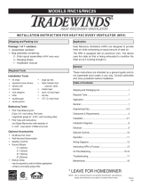
Rain cap (not provided by Gilson)
Rock wall cloth (not provided by Gilson)
3” O.D. Exhaust tubing. (P/N APA-36)
Note: Please consult a local HVAC technician
installing.
Note: Gilson does not supply any materials for
installation other than 3” O.D. exhaust tubing (P/N
APA-36) sold as an accessory
Single Unit Installation Examples

4
Multiple Unit Installation Example
Rain cap (not provided by Gilson)
Rock wall cloth (not provided by Gilson)
*Booster Blower Motor. This booster
should be installed a 10’ and 12’ above the
Damper Control
*Booster Blower Motor should have an ON/OFF toggle switch wired next to the
N-Cat main control panel. The blower motor should only be activated with the
toggle switch when a test is initiated with the N-Cat. Gilson d
Blower Motor. To size an additional booster blower more, please consult an HVAC
technician.
NOTE: Please consult a local HVAC technician
installing.
NOTE: Gilson does not supply any materials for
installation other than 3” O.D. exhaust tubing
(P/N APA-36) sold as an accessory.

5
LIFT TEST PROCEDURE
• The eciency of the furnace exhaust blower and building
exhaust system is monitored by a quick procedure, referred
to as the “lift test”.
• The lift test determines the air ow into and through the
chamber, by lifting the load tray slightly which makes the
scale display value between -3.2 and -10.0 grams.
• The correct air ow allows a complete combustion of the
sample, producing accurate test results.
• If the lift is less than -3.2 grams, an incomplete combustion
of the sample will occur, causing delays in the test.
• This low air ow may allow smoke to ow into the control
compartment and room.
• If the lift is greater than -10 grams, ne-particles from the
sample will be blown away and result in an exaggerated
asphalt content percentage.
STEPS FOR A LIFT TEST:
1. Chamber must be at ambient (room temperature) condition
before attempting a lift test. Allow the unit to cool to ambient
condition. Close the door.
2. On control panel, turn the green power switch to ON. Allow
the unit time to complete the normal scale display count-
down from 9 to 0.
3. Press and release the “0” key on the keypad. This zeros the
balance with the load tray installed.
4. Press and release the “start/stop” key on the keypad. This
starts the exhaust blower motor.
The upper scale display will indicate a measurement
approximately 20 seconds after pressing the “start/stop” key.
The scale display will show the expected negative weight
change, stabilize, then automatically Zero/Tare the value.
5. To view the achieved lift after the automatic Zero/Tare,
press the stop button. This stops the Exhaust fan and stops
the ‘lift’ of the hearth plate. The scale display now shows a
positive value of this lift test.
6. Record the number on paper. The number should be
between –3.2 and –10.0
7. Detach the exhaust tubing and repeat the test to determine
if the exhaust tube is restricting the airow or if the top
plenum of the NCAT is restricting the airow.
If Lift test results are out of range, see next section for eect of
negative air pressure on the NCAT Asphalt Content Furnace,
and verify correct installation as described above.
NEGATIVE AIR PRESSURE EFFECT ON NCAT ASPHALT
CONTENT FURNACE
Air temperature and altitude have an impact on air pressure,
and specically impact the exhaust system on the NCAT
Asphalt Content Furnace.
Negative air pressure refers to a “space” that has less
atmospheric pressure exertion versus another. The “space”
referred here is the room or building the NCAT is installed
compared to the outside atmosphere. (Negative air pressure
can also be thought of as a vacuum.)
If the outside atmospheric air pressure is greater than the
room or building interior air pressure, you have a negative air
pressure condition in the room or building.
The atmospheric pressure will attempt to oset the room or
building pressure and equalize by entering the room through
an open door, window or the exhaust termination of the NCAT
Furnace.
The NCAT has a 60CFM rated blower motor for exhaust. In
some situations, the atmospheric pressure dierence is too
great and the blower motor cannot overcome the external
pressure.
In these situations, Smoke normally generated in the NCAT
will ll the room and/or the lift test will be too low. These issues
are caused by the design of the ventilation system in the
buildings, not the fault of the NCAT.
There are a few options if the NCAT is installed at this type of
location.
• Open any doors or windows in the room. This may be
enough to oset the pressure dierences, allowing the
NCAT to be operated properly.
• Install a second blower motor in-line with the ventilation
tubing from the NCAT. The second blower motor must be
installed beyond the rst 10 feet of exhaust tube. Gilson
does not oer a selection of blower motors for this purpose.
A motor would have to be purchased locally.
• Checking the buildings ventilation system. This is would
require consulting a HVAC technician.
/