Dell Precision Tower 3620 Owner's manual

Category
Notebooks
Type
Owner's manual
Dell Precision Tower 3620
Owner's Manual
Regulatory Model: D13M
Regulatory Type: D13M002
Notes, cautions, and warnings
NOTE: A NOTE indicates important information that helps you make better use of your computer.
CAUTION: A CAUTION indicates either potential damage to hardware or loss of data and tells you how to avoid the problem.
WARNING: A WARNING indicates a potential for property damage, personal injury, or death.
Copyright © 2015 Dell Inc. All rights reserved. This product is protected by U.S. and international copyright and intellectual property laws. Dell
and the
Dell logo are trademarks of Dell Inc. in the United States and/or other jurisdictions. All other marks and names mentioned herein may be trademarks of their
respective companies.
2018 - 07
Rev. A04
Contents
1 Working on your computer............................................................................................................................. 5
Safety instructions............................................................................................................................................................. 5
Before working inside your computer..............................................................................................................................5
Turning o your computer................................................................................................................................................ 6
After working inside your computer.................................................................................................................................6
2 Removing and installing components............................................................................................................. 7
Recommended tools.......................................................................................................................................................... 7
Removing the cover...........................................................................................................................................................7
Installing the cover............................................................................................................................................................. 7
Removing the front bezel.................................................................................................................................................. 7
Installing the front bezel.................................................................................................................................................... 8
Removing the hard drive assembly.................................................................................................................................. 8
Installing the hard drive assembly.................................................................................................................................... 9
Removing the optical drive............................................................................................................................................... 9
Installing the optical drive................................................................................................................................................ 10
Removing power switch.................................................................................................................................................. 10
Installing the power switch..............................................................................................................................................12
Removing the intrusion switch........................................................................................................................................12
Installing the intrusion switch.......................................................................................................................................... 13
Removing the memory module.......................................................................................................................................13
Installing the memory module......................................................................................................................................... 13
Installing the PCIe Solid State Drive SSD...................................................................................................................... 14
Removing the PCIe Solid State Drive SSD ...................................................................................................................15
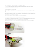
Removing the power supply unit PSU........................................................................................................................... 15
Installing the power supply unit PSU..............................................................................................................................16
Removing the Input-Output panel..................................................................................................................................16
Installing the Input-Output panel.................................................................................................................................... 17
Removing the speaker......................................................................................................................................................17
Installing the speaker........................................................................................................................................................18
Removing the expansion card.........................................................................................................................................18
Installing the expansion card........................................................................................................................................... 19
Removing the system fan................................................................................................................................................19
Installing the system fan..................................................................................................................................................20
Removing the heat sink assembly..................................................................................................................................20
Installing the heat sink assembly....................................................................................................................................20
Removing the processor................................................................................................................................................. 20
Installing the processor.................................................................................................................................................... 21
Removing the system board............................................................................................................................................21
Installing the system board............................................................................................................................................. 22
System board components............................................................................................................................................. 23
3 System Setup.............................................................................................................................................. 25
Contents
3
Boot Sequence.................................................................................................................................................................25
Navigation keys................................................................................................................................................................ 26
System Setup options..................................................................................................................................................... 26
Updating the BIOS ..........................................................................................................................................................33
Jumper settings................................................................................................................................................................34
System and setup password...........................................................................................................................................34
Assigning a system password and setup password............................................................................................... 34
Deleting or changing an existing system and or setup password........................................................................ 35
Disabling a system password....................................................................................................................................35
4 Diagnostics.................................................................................................................................................. 37
Enhanced Pre-Boot System Assessment — ePSA diagnostics................................................................................ 37
Troubleshooting your computer......................................................................................................................................37
Power LED diagnostics..............................................................................................................................................37
Beep code...................................................................................................................................................................38
Error messages...........................................................................................................................................................38
5 Specications..............................................................................................................................................42
6 Contacting Dell............................................................................................................................................ 47
4
Contents
Working on your computer
Safety instructions
Use the following safety guidelines to help protect your computer from potential damage and to help to ensure your personal safety. Unless
otherwise noted, each procedure included in this document assumes that the following conditions exist:
You have read the safety information that shipped with your computer.
A component can be replaced or--if purchased separately--installed by performing the removal procedure in reverse order.
WARNING: Disconnect all power sources before opening the computer cover or panels. After you nish working inside the
computer, replace all covers, panels, and screws before connecting to the power source.
WARNING: Before working inside your computer, read the safety information that shipped with your computer. For additional
safety best practices information, see the Regulatory Compliance Homepage at www.dell.com/regulatory_compliance
CAUTION: Many repairs may only be done by a certied service technician. You should only perform troubleshooting and simple
repairs as authorized in your product documentation, or as directed by the online or telephone service and support team.
Damage due to servicing that is not authorized by Dell is not covered by your warranty. Read and follow the safety instructions
that came with the product.
CAUTION: To avoid electrostatic discharge, ground yourself by using a wrist grounding strap or by periodically touching an
unpainted metal surface, such as a connector on the back of the computer.
CAUTION: Handle components and cards with care. Do not touch the components or contacts on a card. Hold a card by its
edges or by its metal mounting bracket. Hold a component such as a processor by its edges, not by its pins.
CAUTION: When you disconnect a cable, pull on its connector or on its pull-tab, not on the cable itself. Some cables have
connectors with locking tabs; if you are disconnecting this type of cable, press in on the locking tabs before you disconnect the
cable. As you pull connectors apart, keep them evenly aligned to avoid bending any connector pins. Also, before you connect a
cable, ensure that both connectors are correctly oriented and aligned.
NOTE: The color of your computer and certain components may appear dierently than shown in this document.
Before working inside your computer
To avoid damaging your computer, perform the following steps before you begin working inside the computer.
1 Ensure that you follow the Safety instructions.
2 Ensure that your work surface is at and clean to prevent the computer cover from being scratched.
3 Turn o your computer, see Turning o your computer.
CAUTION
: To disconnect a network cable, rst unplug the cable from your computer and then unplug the cable from
the network device.
4 Disconnect all the network cables from the computer.
5 Disconnect your computer and all attached devices from the electrical outlets.
6 Press and hold the power button while the computer is unplugged to ground the system board.
7 Remove the cover.
CAUTION
: Before touching anything inside your computer, ground yourself by touching an unpainted metal surface,
such as the metal at the back of the computer. While you work, periodically touch an unpainted metal surface to
dissipate static electricity, which could harm internal components.
1
Working on your computer 5
Turning o your computer
CAUTION: To avoid losing data, save and close all open les and exit all open programs before you turn o your computer.
1 Turning o your computer:
In Windows 10 (using a touch enabled device or mouse):
1
Click or tap .
2 Click or tap and then click or touch Shut down.
In Windows 8 (using a touch enabled device):
1 Swipe in from the right edge of the screen, opening the Charms menu and select Settings.
2
Tap and then tap Shut down
In Windows 8 (using a mouse):
1 Point to upper-right corner of the screen and click Settings.
2
Click and then click Shut down.
In Windows 7:
1 Click Start.
2 Click Shut Down.
or
1 Click Start.
2 Click the arrow in the lower-right corner of the Start menu and then click Log o.
2 Ensure that the computer and all attached devices are turned o. If your computer and attached devices did not automatically turn o
when you shut down your operating system, press and hold the power button for about 6 seconds to turn them o.
After working inside your computer
After you complete any replacement procedure, ensure that you connect any external devices, cards, and cables before turning on your
computer.
1 Replace the cover.
CAUTION
: To connect a network cable, rst plug the cable into the network device and then plug it into the
computer.
2 Connect any telephone or network cables to your computer.
3 Connect your computer and all attached devices to their electrical outlets.
4 Turn on your computer.
5 If required, verify that the computer works correctly by running Dell Diagnostics.
6
Working on your computer
Removing and installing components
This section provides detailed information on how to remove or install the components from your computer.
Recommended tools
The procedures in this document require the following tools:
Small at blade screwdriver
Phillips screwdriver
Small plastic scribe
Removing the cover
1 Follow the procedure in Before Working Inside Your Computer.
2 Pull the release latch to release the cover [1].
3 Slide the cover and lift the cover to remove it from the computer [2].
Installing the cover
1 Align the cover along its tabs on the chassis of the computer.
2 Press down on the cover until it clicks into place.
3 Follow the procedure in After Working Inside Your Computer.
Removing the front bezel
1 Follow the procedure in Before Working Inside Your Computer.
2 Remove the cover.
3 To remove the front bezel:
2
Removing and installing components 7
a Lift the retention tabs [1] to release the front bezel [2].
b Lift the front bezel to remove it from the computer [3].
Installing the front bezel
1 Hold the bezel and ensure that the hooks on the bezel snap into the notches on the computer.
2 Rotate the front bezel toward the computer.
3 Press the front bezel until the tabs click into place.
4 Install the cover.
5 Follow the procedure in After Working Inside Your Computer.
Removing the hard drive assembly
1 Follow the procedure in Before Working Inside Your Computer.
2 Remove the cover.
3 Disconnect the data cable and the power cable from the hard drive [1].
4 Press the blue securing bracket tabs [2] and lift the hard drive bracket out of the hard drive bay [3].
5 Flex the hard drive bracket and remove the hard drive from the hard drive bracket.
8
Removing and installing components
6 Repeat steps 3 and 4to remove the additional hard drive (if available).
Installing the hard drive assembly
1 Insert the hard drive into the hard drive bracket.
2 Press the securing brackets and slide the hard drive assembly into the hard drive bay.
3 Connect the data cable and the power cable to the hard drive.
4 Install the cover.
5 Follow the procedure in After Working Inside Your Computer.
Removing the optical drive
1 Follow the procedure in Before Working Inside Your Computer.
2 Remove:
a cover
b front bezel
3 Disconnect the data cable and the power cable from the optical drive.
4 To remove the optical drive:
a Slide and hold the optical drive latch to unlock the optical drive [1].
b Slide the optical drive from the computer [2].
Removing and installing components
9
5 Repeat steps 3 and 4 to remove the second optical drive (if available).
Installing the optical drive
1 Slide the optical drive into the drive bay from the front of the computer until it is secured.
2 Connect the data cable and power cable to the optical drive.
3 Install:
a front bezel
b cover
4 Follow the procedure in After Working Inside Your Computer.
Removing power switch
1 Follow the procedure in Before working inside your computer.
2 Remove the:
a Side cover
b Front bezel
c HDD assembly
d Optical drive module
3 To remove the power switch:
a Disconnect the power switch cable from the system board [1].
b Unroute the power switch cable, from the routing clips on the system chassis [2] [3].
10
Removing and installing components
a Remove the screw that secures the power switch on to the system chassis [1].
b Gently push down the power switch module to release it from the slot [2], remove the power switch from the system [3].
Removing and installing components
11
Installing the power switch
1 Align and slide the power switch module into the slot on the chassis until it clicks into place.
NOTE
: Ensure that the power switch cable is routed correctly through the cable routing clips on the system chassis.
2 Connect the power switch cable to the connector on the system board.
3 Install the:
a Optical drive module
b HDD assembly
c Front bezel
d Side cover
4 Follow the procedure in After working inside your computer.
Removing the intrusion switch
1 Follow the procedure in Before Working Inside Your Computer.
2 Remove the cover.
3 To remove intrusion switch:
a Press the tab to disconnect the intrusion switch cable from the system board [1, 2].
b Slide the knob of the intrusion switch toward the bottom of the chassis [3].
12
Removing and installing components
c Pull the intrusion switch to remove it from the slot [4].
Installing the intrusion switch
1 Insert the intrusion switch into the slot in the chassis.
2 Slide the intrusion switch to secure it.
3 Connect the intrusion switch cable to the system board.
4 Install the cover.
5 Follow the procedure in After Working Inside Your Computer.
Removing the memory module
1 Follow the procedure in Before Working Inside Your Computer.
2 Remove the cover.
3 Press the memory module retention tabs on each side of the memory module.
4 Lift the memory module out of the connectors on the system board.
Installing the memory module
1 Align the notch on the memory module with the tab on the memory module connector.
2 Insert the memory module into the memory module socket.
3 Press the memory module until the retention tabs clicks into place.
4 Install the cover.
5 Follow the procedure in After Working Inside Your Computer.
Removing and installing components
13
Installing the PCIe Solid State Drive SSD
NOTE: The PCIe SSD card is shipped with the following components:
1 PCIe SSD card
2 Thermal Pad
3 Screw
1 Follow the procedure in Before Working Inside Your Computer.
2 Remove the:
a cover
b hard drive
c optical drive
3 Peel the blue adhesive tape from the thermal pad.
4 Place the thermal pad in the slot on the system board and peel the pink adhesive tape [1,2].
5 Slide the PCIe SSD card into the slot and tighten the screw to secure the card to the system board [1,2].
14
Removing and installing components
Removing the PCIe Solid State Drive SSD
1 Remove the screw that secures the PCIe SSD card.
2 Slide and lift the PCIe SSD card from the computer.
3 Lift the thermal pad from the system board.
4 Install the:
a optical drive
b hard drive
c cover
5 Follow the procedure in After Working Inside Your Computer.
Removing the power supply unit PSU
1 Follow the procedure in Before Working Inside Your Computer.
2 Remove the cover.
3 Press the tab of the 4-pin power cables and disconnect it from the system board [1,2].
4 Release the cables from the clip [3].
5 To remove the power supply unit (PSU):
a Remove the screws that secure the PSU to the computer [1].
Removing and installing components
15
b Disconnect the PSU cables from the connectors on the system board.
c Unroute the PSU cables from the retention clips.
d Press the metal release tab [2], slide [3] and lift the PSU out of the computer [4].
Installing the power supply unit PSU
1 Insert the PSU into the PSU slot and slide it toward the back of the computer until it clicks into place.
2 Tighten the screws to secure the PSU to the computer.
3 Route the PSU cables through the retention clips.
4 Connect the PSU cables to the connectors on the system board.
5 Install the cover.
6 Follow the procedure in After Working Inside Your Computer.
Removing the Input-Output panel
1 Follow the procedure in Before Working Inside Your Computer.
2 Remove:
a cover
b front bezel
3 To remove the I/O panel:
a Disconnect the I/O panel, and USB data cables from the system board [1,2,3,4].
b Remove the screw that secures the I/O panel to the computer [5].
c Slide the I/O panel toward the left of the computer to release it and pull the I/O panel along with its cable out of the computer
[6].
16
Removing and installing components
Installing the Input-Output panel
1 Insert the I/O panel into the slot on the front of the chassis.
2 Slide the I/O panel toward the right of the computer to secure it to the chassis.
3 Tighten the screw to secure the I/O panel to the chassis.
4 Connect the I/O panel, and USB data cable to the system board.
5 Install :
a front bezel
b cover
6 Follow the procedure in After Working Inside Your Computer.
Removing the speaker
1 Follow the procedure in Before Working Inside Your Computer.
2 Remove the cover.
3 To remove the speaker:
a Disconnect the speaker cable from system board [1].
b Press the securing tab on the speaker to slide and remove the speaker from the chassis [2, 3].
Removing and installing components
17
Installing the speaker
1 Slide the speaker module into the slot to secure it.
2 Connect the speaker cable to the system board.
3 Install the cover.
4 Follow the procedure in After Working Inside Your Computer.
Removing the expansion card
1 Follow the procedure in Before Working Inside Your Computer.
2 Remove the cover.
3 Press the securing tab to release the card retention lock [1, 2].
4 To remove the expansion card:
a Push the release latch to release the expansion card [1].
b Lift the card out of the connector [2].
18
Removing and installing components
Installing the expansion card
1 Insert the expansion card in the connector on the system board and press it until clicks into place.
2 Close the release latch.
3 Install the cover.
4 Follow the procedure in After Working Inside Your Computer.
Removing the system fan
1 Follow the procedure in Before Working Inside Your Computer.
2 Remove the cover.
3 To remove the system fan:
a Disconnect the system fan cable from the system board [1].
b Stretch the grommets securing the fan to the computer to ease the removal of the fan [2].
c Slide and lift the system fan from the computer [3].
Removing and installing components
19
Installing the system fan
1 Hold the system fan by the sides with the cable end facing the bottom of the computer.
2 Pass the four grommets through the chassis and slide outward along the groove to secure the system fan.
3 Connect the system fan cable to the system board.
4 Install the cover.
5 Follow the procedure in After Working Inside Your Computer.
Removing the heat sink assembly
1 Follow the procedure in Before Working Inside Your Computer.
2 Remove the cover.
3 To remove the heat sink assembly:
a Disconnect the heat sink cable from the system board [1].
b Loosen the captive screws in diagonal order [2].
c Lift the heat sink assembly away from the computer [3].
Installing the heat sink assembly
1 Place the heat sink assembly on the processor.
2 Tighten the captive screws in diagonal order to secure the heat sink assembly to the computer.
3 Connect the heat sink cable to the system board.
4 Install the cover.
5 Follow the procedure in After Working Inside Your Computer.
Removing the processor
1 Follow the procedure in Before Working Inside Your Computer.
2 Remove the:
a cover
b front bezel
c hard drive
d heat sink
20
Removing and installing components
  • Page 1 1
  • Page 2 2
  • Page 3 3
  • Page 4 4
  • Page 5 5
  • Page 6 6
  • Page 7 7
  • Page 8 8
  • Page 9 9
  • Page 10 10
  • Page 11 11
  • Page 12 12
  • Page 13 13
  • Page 14 14
  • Page 15 15
  • Page 16 16
  • Page 17 17
  • Page 18 18
  • Page 19 19
  • Page 20 20
  • Page 21 21
  • Page 22 22
  • Page 23 23
  • Page 24 24
  • Page 25 25
  • Page 26 26
  • Page 27 27
  • Page 28 28
  • Page 29 29
  • Page 30 30
  • Page 31 31
  • Page 32 32
  • Page 33 33
  • Page 34 34
  • Page 35 35
  • Page 36 36
  • Page 37 37
  • Page 38 38
  • Page 39 39
  • Page 40 40
  • Page 41 41
  • Page 42 42
  • Page 43 43
  • Page 44 44
  • Page 45 45
  • Page 46 46
  • Page 47 47

Dell Precision Tower 3620 Owner's manual

Category
Notebooks
Type
Owner's manual

Ask a question and I''ll find the answer in the document

Finding information in a document is now easier with AI