Lyman AV 75DC Tumbler Operating instructions
- Type
- Operating instructions

Operating Instructions
Models
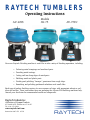
AV-40SS AV-75 AV-75DC
Your new Raytech Finishing machine is useful for a wide variety of finishing operations, including:
• Deburring metal stampings and machined parts.
• Descaling metal castings.
• Cutting radii on sharp edges of metal parts.
• Polishing metal and plastic parts.
• Grinding and polishing “baroque” gemstones from rough chips.
• Smoothing and polishing preformed cabochons and small slabs.
Each type of product finishing requires its own sequence of steps with appropriate abrasives, pol-
ishes and medias. These instructions focus on operating the Adjusta-Vibe finishing machines only.
Consult your distributor for recommended media and compounds.
Raytech Industries
A Division of Lyman Products
475 Smith Street, Middletown, CT 06457
Tel (860) 632-2020
www.raytech-ind.com
Instruction #04315R 05/22
RAYTECH TUMBLERS

General Operating Instructions
Your new Raytech Adjusta-Vibe finishing machine comes from the factory completely assembled and ready to run. The
working capacity of the Adjusta-Vibe 40 and 40SS is .35 cubic feet, or three gallons. The working capacity of the model
75 is .75 cubic feet, or approximately 6 gallons. This capacity includes both the media and the workpieces. The gener-
al rule of thumb is 70% media and 30% parts. Raytech finishing machines are actuated by an eccentric weight system
which is factory set at the mid-range tumbling action. By adjusting the eccentric weights, the amplitude of the machine
can be changed infinitely, resulting in vibratory action ranging from mild to very aggressive, depending on media and
material being tumbled, e.g. corncob media/mild tumbling action, and ceramic media/more tumbling action.
Maintenance
The following maintenance should be performed every 500 hours of use:
1. Lubricate lower shaft assembly threads and motor plate threads with a light grease such as Lubriplate.
2. Check tightness of all hardware.
3. Inspect interior of bowl to ascertain any premature wear.
Health & Safety Cautions
1. Do not cover the machine with anything (such as a blanket or a box) to insulate the noise as this could cause over-
heating and become a fire hazard.
2. Always connect the machine to a power source that has been properly grounded to prevent any possible electrical
shock.
3. Models 40 and 75 are designed not to “walk” during normal operation. We recommend that the machine be placed
on a solid floor away from any combustible materials. If the machine is used on a bench, it should be blocked in to
prevent any accidents. Do not bolt or attach these units to a workbench by any means, as this will void warranty.
4. Prior to any adjustments to the eccentric weight assembly, disengage the machine from its electrical power source.
5. Never attempt to operate or experiment with other than recommended media and compounds.
6. Do not dispose of grits down drain. Remove as much grit as possible by straining.
7. Always use ear protection in the work area while the machine is running. Machine noise level at maximum condi-
tions is 82 dB. Noise levels can be less depending on media applications.
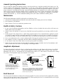
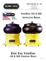
Amplitude Adjustment
To change the amplitude, unplug the electric cord and turn the machine on its side. Remove the bottom cover with the
three #8 seIf-tap screws. Use a 5/16” Allen wrench to adjust the eccentric weights. Refer to Figures I and 2 below for
adjustment, Note: The 5/16” Allen head bolt is a left-hand thread. With a 5/16” Allen wrench, loosen this bolt to change
the position of the adjustable weight. Once adjusted, secure tightly.
Bowl Removal
Note: Never turn the machine on without the bowl being installed. To remove the bowl from the Adjusta-Vibe machine,
unscrew the large nut at the center of the bowl and lift off. When replacing the bowl, it is essential that the nut be tight-
ened properly so that the bowl will not vibrate loose.
FIGURE 1: FIGURE 2: FIGURE 3:
Figure 1 shows weight adjusted to
minimum amplitude/aggressiveness.
Adjustable weight in this position
counter balances the fixed weight and
reduces the amplitude/aggressive-
ness. (Ex. Tumbling using corncob
media or any light media.) Figure 2 shows weight adjusted to maximum amplitude/
aggressiveness. Adjustable weight in this position adds
to the fixed weight and increases the amplitude/aggres-
siveness. (Ex. Tumbling using ceramic or steel shot
media or any heavy media.)
With a 5/16” Allen wrench,
loosen this bolt to change
position of adjustable weight.
CAUTION:
Do not loosen
this screw
when chang-
ing adjustable
weight position.
Fixed Weight
Adjustable Weight
Recommended Position
for Light Media
Center Line of Media Shaft

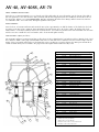
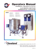
AV-40, AV-40SS, AV-75
SHAFT ASSEMBLY INSTALLATION:
Screw the 1/2-13 nut approximately 1-1 1/2” from the end of the shaft. Place the 9/16” flat washer onto the bottom of the shaft so
that it is against the 1/2-13 nut. insert the shalt, preferably with thread-locking liquid (such as Loctite®) into the threaded center of
the motor plate. Tighten 7 to 9 turns FINGER TIGHT. Excessive tightening will cause motor damage. When bottomed out, unscrew
1-1/4 full turns. run a 1/2-13 nut down, and tighten against the motor plate.
BOWL ASSEMBLY:
Screw both 1/2-13 hex nuts and brass stud toward the motor plate, approximately one-half the distance of the shaft. Place the bowl
in position on the motor plate. Adjust the brass stud until the amount showing above the bowl is equal to the height of the bowl
washer and the 1-8 hex nut combined. Remove the bowl and use the 1/2-13 nut as a jam nut for the brass stud. Make sure the brass
stud does not move. Install the bowl, bowl washer, and 1-8 hex nut and tighten securely.
NOTE ON THE A V-JOSS (Steel Shot):
The AV-40SS bowl has a special spout and plug to allow the steel shot to drain from the bowl when needed. To drain the bowl of steel
shot, turn the T-handle on the plug counterclockwise until it is loose and then remove. Drain the steel shot as desired. Wipe clean the
interior of the spout and the rubber ridges on the drain plug prior to resealing it. Loosen the plug into the drain spout and turn the T
-handle clockwise until you feel resistance. The plug is now sealed again and the tumbler is ready to run.
ITEM PART NO. DESCRIPTION QTY
1 07967R Shaft Assembly AV-40 1
1 07965R Shaft Assembly AV-75 1
2 07943R Cover Wing/Perm Nut Assembly 1
3* 23032R Bowl with Cover AV-40 1
3** 23046R Bowl with Cover AV-75 1
4 03376R Nut 1” -8 Hex Full Zc 1
5 07925R Bowl Holddown Plate 1
6 03249R Washer 9/16 Flat 1
7 07779R Rubber Pad 5
7a 07796R Top Pad Cut (Not Shown) 1
8 03299R Hex Head Screw 5/16 - 18 x 1 1/2 6
9 07773R Motor Plate 1
11 07942R Spring Grommet 12
12 03243R Washer 5/16 USS STD 12
13 03349R Nut 5/16-18 Hex Zc 6
14 03284R Hex Head Screw5/16-18 x 1 1/4 6
15 03243R Washer 5/16 USS STD 6
16 03480R Carriage Bolt 3/8-16 x 8” Long 4
17*** 30255R Motor 40/75 110V 1
17*** 30293R Motor 40/75 230V 1
18 03325R Jack Nut Molly #10-24 4
19 03388R Nut 3/8-16 Locking 4
20 07772R Motor Bar 1
21 07972R Counterweight Assy 1
22 07784R Bottom Cover 1
23 03440R Screw #8 x 3/8 Typ A Pan 3
24 07882R Rubber Feet 3
25**** 07782R Base Model 40 1
25**** 07783R Base Model 75 1
26 07941R Compression Spring 6
27 03462R Screw #10-32x3/8 Pan Zc 3
28 07781RP Strap for Capacitor 1
29 03929R Capacitor 115V /230V 1
30 07909R Strainer Fitting 1
31 03374R Nut 3/4-16 Jam Zc 1
32 07936R Drain Tube 3/8 LD x 30” S/A 1
* Includes 30,31,32 (Not Shown)
** Includes 30,31,32 (Not Shown)
*** Includes 7,7a,9,11,12,13,16,17,19,20,28,29
**** Includes 11,14,15,18,22,23,24,25
1
2
34
5
6
7
8
9
11
12
13
14
16
17
18
19
20
21
22
23
24
25
26
27
28
29
30
31
15

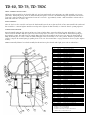
TD-40, TD-75, TD-75DC
SHAFT ASSEMBLY INSTALLATION:
Holding the shaft assembly by the threaded shaft only (not brass stud) install center stud spring onto shaft assembly (end opposite
pinned nut). With spring end up, insert the shaft assembly through the center tube and Tumble-Dump plate until brass stud contacts
center tube. Apply Loctite® onto brass stud and screw into center tube - approximately 4 turns - until wrench flats on brass stud are
flush with center tube. Set aside to dry.
BOWL ASSEMBLY:
Place the bowl over the center hole and screw the shaft assembly into the motor plate and back off two turns. Install bowl washer and
fasten with the 1-8 nut and tighten. With the wrench provided, tighten the shaft assembly to obtain the desired operating tightness.
TUMBLE-DUMP FEATURE:
Raytech’s Tumble-Dump models (TD-40 and TD-75) feature a built-in hinge system that allows the parts and media to be easily
removed from the machine. With the special 3/4” hex wrench provided, loosen the 3/4” hex nut until the shaft and nut spring up -
approximately 6 turns. This will release the tumble-dump plate and bowl assembly from the motor plate. Raise the dump handle to
dump media and parts. To secure, return the tumble-dump plate and bowl assembly to the “run” position. With the special wrench
provided, compress the internal spring by pushing down on the 3/4” hex nut and turn to engage threads into the motor plate. Tighten
securely.
NOTE: Occasionally lubricate lower shaft assembly threads and motor plate threads with a light grease such as “Lubri-Plate.”
ITEM PART NO. DESCRIPTION QTY
1 07968R Shaft Assembly TD-40 1
1 07966R Shaft Assembly TD-75 1
2 07943R Cover Wing/Perm Nut Assembly 1
3* 23032R Bowl with Cover AV-40 1
3** 23046R Bowl with Cover AV-75 1
4 03376R Nut 1” -8 Hex Full Zc 1
5 07925R Bowl Holddown Plate 1
6 07883R Center Stud Spring 1
7 08377R Tilting Plate TD-40 1
7 07933R Tilting Plate TD-75 1
8 07796R Top Pad Cut (Not Shown) 1
8a 07779R Rubber Pad 5
9 03299R Hex Head Screw 5/16 - 18 x 1 1/2 6
10 07773R Motor Plate 1
12 07941R Compression Spring 6
13 07942R Spring Grommet 12
14 2990617 Washer 5/16 USS STD 12
15 8033900P Nut 5/16-18 Hex Zc 6
16 03284R Hex Head Screw5/16-18 x 1 1/4 6
17 07942R Spring Grommet 12
18 03480R Carriage Bolt 3/8-16 x 8” Long 4
19*** 30255R Motor 40/75 110V 1
19*** 30293R Motor 40/75 230V 1
20 03325R Jack Nut Molly #10-24 4
21 07772R Motor Bar 1
22 03356R Nut 3/8-16 Locking 4
23 07972R Counterweight Assy 1
24 07784R Bottom Cover 1
25 03440R Screw #8 x 3/8 Typ A Pan 3
26 07882R Rubber Feet 3
27**** 07782R Base Model 40 1
27**** 07783R Base Model 75 1
28 07941R Compression Spring 6
29 03462R Screw #10-32x3/8 Pan Zc 3
30 07781RP Strap for Capacitor 1
31 03929R Capacitor 115V/230V 1
32 03065R Screw 1/4-20 x 1 1/4 Hex Zc 4
33 07923R Hinge Pivot Block 2
34 07770R Hinge Bar 1
35 07920R Tilting Hinge 2
36 07909R Strainer Fitting 1
37 03374R Nut 3/4-16 Jam Zc 1
38 03055R Screw 1/4-20 x 3/4 Hex Zc 4
39 07936R Drain Tube 3/8 LD x 30” S/A 1
* Includes 36,37,39 (Not Shown)
** Includes 36,37,39 (Not Shown)
*** Includes 8,8a,9,10,13,14,15,18,19,21,22,29
**** Includes 14,16,17,20,24,25,26,27
1
2
34
5
6
7
8
9
10
12
13
14
16
17
18
19
20
21
22
23
24
25
26
27
28
29
30
31
15
32
33
34
35
36
37
38
-
 1
1
-
 2
2
-
 3
3
-
 4
4


Lyman AV 75DC Tumbler Operating instructions
- Type
- Operating instructions
Ask a question and I''ll find the answer in the document
Finding information in a document is now easier with AI
Other documents
-
 BURR KING Model 15 User manual
-
 BURR KING Model 150s/200s User manual
-
Chicago Electric 96923 Owner's Manual & Safety Instructions
-
-
Harbor Freight Tools Item 67617 Owner's manual
-
 Cleveland SE95022 R6 (Mixer HA Gas) User manual
-
Powermatic 1794224K User manual
-
-
-
JET JWL-1440VS Owner's manual


