BANTE BI-680 Industrial Dissolved Oxygen Controller User manual
- Category
- Measuring, testing & control
- Type
- User manual
This manual is also suitable for

BI-680 Industrial Dissolved Oxygen Controller
USER MANUAL
Bante Instruments Inc.

1 I Overview
Introduction
Thank you for selecting the BI-680 dissolved oxygen controller. This user
manual provides a step-by-step guide to help you operate the meter,
please carefully read the following instructions before use.
Environmental Conditions
Before the installation, ensure that current environmental conditions
meet the following requirements.
• Relative humidity is less than 80%
• Ambient temperature between 5°C (41°F) and 50° C (122° F)
• No potential electromagnetic interference
• No corrosive gas exists
Packing List
The following list describes all components of the meter. If any items
are missing or damaged, contact the supplier immediately.
BI-680 dissolved oxygen controller
IE-80T industrial dissolved oxygen electrode
Membrane cap and electrolyte solution
Installation
Safety Warning
• BI-680 meter shall be installed and operated only in the manner
specified in this user manual.
• Only skilled, trained or authorized person should carry out
installation, setup and operation of meter.
• The rear panel of meter has two screw terminals for connecting
the 24V DC power supply. Make sure to cut off the main power
before installation and maintenance.
• Once the power supply cable is connected to the meter, DO NOT
touch any screw terminals.
Installing the Meter
1.1 Cut out a square hole approximately 91 × 91 mm (3.58 × 3.58 in.)
in the mounting panel.
1.2 Remove the mounting bracket, place the meter into the square
hole.
1.3 Replace the mounting bracket and push the meter forward until
it is fully seated on the mounting plate.
Installing the Electrode
2.1 Take out the dissolved oxygen electrode from the packaging.
Unscrew the membrane cap from the bottom of the electrode,
rinse the inside and outside with distilled water and blot dry.
2.2 Fill the membrane cap halfway with electrolyte solution.
2.3 Screw membrane cap back onto the electrode. Some electrolyte
solution will overflow during this process.
2.4 Check the electrode, ensure that no air bubbles are trapped in the
electrolyte solution and membrane is not creased or damaged.
2.5 Wrap Teflon tape to the electrode body threads.
2.6 Insert the electrode into the mounting position and slowly turn
clockwise until secure. Hand tighten the electrode to prevent
liquid leakage.
91 mm
91 mm
Mounting bracket
Remove air bubbles

Overview I 2
Connection
No.
Terminal
Description
1
DO (−)
Dissolved oxygen input (−)
2
DO (+)
Dissolved oxygen input (+)
3
---
No connection
4
---
No connection
5
TC (−)
Temperature input (−)
6
TC (+)
Temperature input (+)
7
485 (B)
RS485 signal output (B)
8
485 (A)
RS485 signal output (A)
9
DC 24 (+)
DC 24V (+), linear power supply 1
10
DC 24 (−)
DC 24V (−), linear power supply 1
4 to 20 mA analog output
11
GND
Earth ground
12
DC 24 (+)
DC 24V (+), linear power supply 2
13
DC 24 (−)
DC 24V (−), linear power supply 2
14
NC2
Relay resting position (NC2)
15
NO2
Relay working position (NO2)
16
COM2
Relay common (COM2)
17
NC1
Relay resting position (NC1)
18
NO1
Relay working position (NO1)
19
COM1
Relay common (COM1)
20
---
No connection
Meter Overview
Display
Icon
Description
Calibration
Indicates that the meter is in the calibration mode
Setup
Indicates that the meter is in the setup mode
ATC
Indicates that the automatic temperature
compensation is enabled
ALM1
Indicates the measurement exceeded the high limit
ALM2
Indicates the measurement exceeded the low limit
Keypad
Key
Function
• Switch the meter on or off
• Press and hold the key to enter the setup menu
• Exit the calibration, settings and return to the
measurement mode
• Start calibration
• Increase value or scroll up the menu items
• Set the temperature
• Decrease value or scroll down the menu items
• Select the measurement mode
• Confirm the calibration, setting or displayed option
DC 24V (+), linear
power supply 1
Current detection
4 to 20 mA
DC 24V (−), linear
power supply 1
DC 24V (+), linear
power supply 2
DC 24V (−), linear
power supply 2
1
10
11
20

3 I Setup
Meter Setup
The BI-680 meter contains an integrated setup menu for customizing
the displayed option to meet measurement requirement. The following
table describes the functions of each menu item.
Menu Item
Option and Description
Salinity Coefficient
Set the salinity compensation coefficient of sample.
0 to 35 g/L (default 0 g/L)
Pressure Coefficient
Set the barometric pressure coefficient according to
the local altitude (refer to page 4).
450 to 850 mmHg (default 760 mmHg)
Calibration Points
Set the number of calibration points.
1 point (default)
2 points
Measurement Unit
Set the default measurement unit.
mg/L
Milligrams per liter (default)
ppm
Parts per million
%
Percentage saturation
Degrees Celsius (default)
Degrees Fahrenheit
Low Alarm Limit
Setting range: 0.00 to 20.00 mg/L (default 4.00)
High Alarm Limit
Setting range: 20.00 to 0.00 mg/L (default 10.00)
Hysteresis Value
Setting range: 0.01 to 0.10 mg/L (default 0.1)
Analog Output (Low)
Setting range: 0.00 to 20.00 mg/L (default 4.00)
Analog Output (High)
Setting range: 20.00 to 0.00 mg/L (default 10.00)
Factory Reset
Reset the meter to factory default settings. Note,
the meter must be recalibrated.
Enable
Disable (default)
• If the high or low alarm is enabled, the meter will be activated
when the measurement exceeds specified limit. Note, this option
can not enter the same values.
• If the hysteresis is enabled, the meter will prevent rapid contact
switching when the measurement is fluctuating near the set
point. For example, you have set the high alarm at 20 mg/L and
hysteresis value at 0.1 mg/L. When the measurement overshoots
the 20.1 mg/L, the meter will activate an external device. When
the measurement drops to 19.9 mg/L, the device will switch off.
• The default RS485 communication is 4.00 to 10.00 mg/L
corresponds to the 4.00 to 20.00 mA.
Setting a Default Option
1. In the measurement mode, press and hold the key to enter the
setup menu.
2. Press the / key to select a menu item, press the Enter key
to confirm.
3. Press the / key to select an option or set a value, press the
Enter key to save.
To exit the setup menu without saving changes, press the key.
Menu
item
Page
number
Option
Menu
item

Calibration and Measurement I 4
The following table describes the relationship between the altitude
and barometric pressure, make sure to set a compatible parameter
before the calibration and measurement.
Altitude (m)
kPa
mmHg
Altitude (m)
kPa
mmHg
0
101.3
760
1600
82.9
622
100
100.1
750
1700
81.9
614
200
98.8
741
1800
80.9
607
300
97.6
732
1900
79.9
599
400
96.4
723
2000
78.9
592
500
95.2
714
2100
77.9
584
600
94.0
705
2200
76.9
577
700
92.8
696
2300
76.0
570
800
91.7
688
2400
75.0
563
900
90.5
679
2500
74.1
556
1000
89.4
671
2600
73.2
549
1100
88.3
662
2700
72.3
542
1200
87.2
654
2800
71.4
536
1300
86.1
646
2900
70.5
529
1400
85.0
638
3000
69.6
522
1500
84.0
630
3100
68.7
515
Temperature Compensation
The BI-680 meter is supplied with an industrial dissolved oxygen
electrode. When the wires of electrode are connected to the meter,
the display will show ATC icon immediately. The meter is now switched
to the automatic temperature compensation mode.
Temperature Calibration
During the measurement, if the measured temperature reading differs
from that of an accurate thermometer, the electrode needs to be
calibrated.
1. Place the electrode into a solution with a known accurate
temperature.
2. Press the °C key to enter the temperature setting.
3. Press the / key to modify the temperature value.
4. Press the Enter key to save.
Dissolved Oxygen Calibration
The BI-680 meter is able to perform either 1 or 2 points calibration.
For single point calibration, we recommend that you perform 100%
saturation calibration in the air-saturated water. If the 2 points
calibration is selected, the zero oxygen solution needs to be used.
Single Point Calibration
1.1 Make sure that you have selected 1 point calibration in the setup
menu.
1.2 Press the Cal key, the display shows 100%/CAL1.
1.3 Hold the dissolved oxygen electrode in the air at 100% relative
humidity or place the electrode into the air-saturated water for
about 10 minutes.

5 I Calibration and Measurement
Press the Enter key to begin the calibration.
1.4 When the reading has stabilized, the meter will show and
return to the measurement mode.
2 Points Calibration
2.1 Ensure that you have selected 2 points calibration in the setup
menu.
2.2 Repeat steps 1.2 and 1.3 above. When the first calibration point.
is completed, the display will show 0%/CAL2, the meter prompts.
you to continue with second point calibration.
2.3 Place the dissolved oxygen electrode into the zero oxygen solution.
for about 10 minutes.
Press the Enter key to begin the calibration.
2.4 When the reading has stabilized, the meter will show .
Calibration is completed.
• Performing a percentage saturation calibration will calibrate the
corresponding mg/L or ppm concentration value simultaneously.
• To exit the calibration without saving calibrated values, press the
key.
Measurement
The BI-680 meter can be used to measure the water, wastewater,
brine and other liquids. If your sample is seawater or water containing
large amounts of salt, make sure to set the salinity coefficient before
measurement. Some gas and steam such as chloride, sulfur dioxide,
sulfureted hydrogen and carbon dioxide can permeate the membrane
via diffusion. Their existence will influence the measurements. If the
sample contains solvent, grease, sulfide and alga, the membrane will
be damaged or eroded.
1. Press the key to select the mg/L or % saturation measurement
mode.
2. Set the barometric pressure and salinity coefficient in the setup
menu.
3. Place the electrode into the sample. Wait for the measurement
to stabilize.

Communication I 6
Communication
The BI-680 meter uses a standard Modbus-RTU protocol. All of the
data are character type (2 bytes). The response data ranges between
-32767 to 32767, hexadecimal.
PC Command
Definition
Length of Byte
Data
ID address
1
0 × 03
Command
1
0 × 03
Start address
2
0 × 0001
Data number
2
0 × 0002
CRC16
2
0 × 9429
Meter Response
Definition
Length of Byte
Data
ID address
1
0 × 03
Command
1
0 × 03
Data Length
1
0 × 0002
Data
N
0 × 02 0 × BC
CRC16
2
0 × E539
• If the response is 01 indicating the command is error.
• If the response is 02 indicating the address is incorrect.
• If the response is 03 indicating the byte length is incorrect.
Command 03: Read the data from the measurement
Command 04: Read the data from the setting
• ID: 0 × 03 (Fixed)
• 03: Definition
Address:
0 × 0000 - Dissolved oxygen reading
0 × 0001 - Measurement unit
0 × 0002 - Temperature (Reading × 0.1)
• 04: Definition
Address:
0 × 0000 - Read the low alarm limit
0 × 0001 - Read the high alarm limit
0 × 0002 - 4.00 mA correspond to the dissolved oxygen value
0 × 0003 - 20.00 mA correspond to the dissolved oxygen value
Measurement Unit Response:
0 × 0001: mg/L
0 × 0002: ppm
0 × 0003: %
For Example (Hexadecimal):
PC send: 03 03 00 00 00 02 C5 E9 (Read the DO)
Response: 03 03 02 02 BC C1 55 (700)
PC send: 03 03 00 01 00 02 94 29 (Read the unit)
Response: 03 03 02 00 01 00 44 (mg/L)
The result will show 7.00 mg/L (700 × 0.01 mg/L)
Electrode Maintenance
In order to maintain an accurate measurement, the dissolved oxygen
electrode needs cleaning and regular maintenance.
• Rinse the electrode with clear water to remove deposits.
• If necessary, fill the electrolyte solution to membrane cap.
• If you do not use the electrode for long periods, screw off the
membrane cap, rinse the electrode anode, cathode, membrane
cap with distilled water and blot dry. Install the electrode and
store dry.
Cathode Anode
Appendix
Troubleshooting
Fault
Cause and Corrective Action
Screen shows
Dissolved oxygen electrode does not connect to the
meter or measured value is out of range.
Drifting erratic
readings
Check whether the membrane cap is contaminated
or the electrolyte solution is depleted.
Screen shows
Electrode is broken.
Replace the dissolved oxygen electrode.
Preparation of Air-Saturated Water
Use an air-pump to blow air into distilled water at least 1 hour, while
stirring the solution.
Preparation of Zero Oxygen Solution
Dissolve 500 mg of the sodium sulfate (Na2SO3) reagent and a small
amount of cobalt (II) chloride hexahydrate (CoCl2 • 6H2O) in the 250 ml
distilled water, mix the solution until reagent is completely dissolved.

7 I Appendix
Optional Accessories
Order Code
Description
IE-80T
Dissolved oxygen electrode, range: 0 to 20 mg/L
DO-MEM
Membrane cap, 2 PCS/set
DO-ES
Electrolyte solution, 30 ml
Meter Specifications
Model
BI-680
Dissolved Oxygen
Range
0.00 to 20.00 mg/L
Resolution
0.01 mg/L
Accuracy
± 0.5 mg/L
% Saturation
Range
0.0 to 200.0%
Resolution
0.1%
Accuracy
± 2.0%
Temperature
Range
0 to 50° C (32 to 122° F)
Resolution
0.1° C (0.1° F)
Accuracy
± 1° C (± 1.8° F)
Calibration Point
1 point
Communication
Signal Output
4 to 20 mA
Low or High Alarm
0.00 to 20.00 mg/L
Load
500 Ω
Communication Interface
RS485
Other Specifications
Operating Temperature
5 to 50° C (41 to 122° F)
Storage Temperature
0 to 60° C (32 to 140° F)
Relative Humidity
< 80% (non-condensing)
Display
LCD, 70 × 45 mm (2.9 × 1.7 in.)
Power Requirements
DC 24V
Dimensions
96 (L) × 96 (W) × 75 (H) mm,
(3.7 × 3.7 × 2.9 in.)
Weight
350 g (12.3 oz.)

The information in this document is subject to change without notice.
Copyright © Bante Instruments Inc, 2022. All rights reserved.
Disposal
This product is required to comply with the European Union’s Waste
Electrical and Electronic Equipment (WEEE) Directive 2002/96/EC and
may not be disposed of in domestic waste. Please dispose of product
in accordance with local regulations at the collecting point specified
for electrical and electronic equipment.
Warranty
The warranty period for meter is one year from the date of shipment.
Above warranty does not cover the electrode and electrolyte solution.
Out of warranty products will be repaired on a charged basis.
The warranty on your meter shall not apply to defects resulting from:
• Improper or inadequate maintenance by customer
• Unauthorized modification or misuse
• Operation outside of the environment specifications of the
products.
For more information, please contact the supplier.
Office: 4715 Castlewood St., Sugar land, TX 77479, USA
Tel: (+1) 346-762-7358
E-mail: banteinstruments@yahoo.com
Factory: F3, Building 2, No.2185, Laifang Rd., Shanghai 201615, China
Tel: (+86) 21-6404-1598
E-mail: banteinstrument@hotmail.com
www.bante-china.com
-
 1
1
-
 2
2
-
 3
3
-
 4
4
-
 5
5
-
 6
6
-
 7
7
-
 8
8
-
 9
9
BANTE BI-680 Industrial Dissolved Oxygen Controller User manual
- Category
- Measuring, testing & control
- Type
- User manual
- This manual is also suitable for
Ask a question and I''ll find the answer in the document
Finding information in a document is now easier with AI
Other documents
-
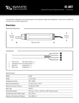 Bante Instruments IE-80T Industrial Dissolved Oxygen Electrode Owner's manual
-
 Bante Instruments series Portable pH/ORP/Ion/Conductivity/DO Meter Owner's manual
-
 Bante Instruments 9 series Benchtop pH/ORP/Ion/Conductivity/DO Meter Owner's manual
-
 Bante Instruments A series Laboratory pH/ORP/Ion/Conductivity/DO Meter Owner's manual
-
 Bante Instruments Dissolved Oxygen Electrode Owner's manual
-
 Bante Instruments S series Bluetooth pH/ORP/Ion/Conductivity/DO Tester Owner's manual
-
 AMTAST EC910 User manual
-
 Bante Instruments 810 Benchtop Dissolved Oxygen Meter Owner's manual
-
EUTECH INSTRUMENTS WD-35414-20 Owner's manual
-
Extech Instruments DO700 User manual


