Page is loading ...

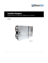
Typical Damper Shown
HE07 and HE10
HE1.5X through HE8X
LE-Series
Isolation Dampers
Supplemental Manual for Options

1.800.627.44992
Isolation Dampers
OPTION
READ AND SAVE THIS MANUAL/LIRE ET CONSERVER CE MANUEL
UNIT INFORMATION
Record information as shown below.
In the unlikely event that factory assistance is ever required, information located on the unit
label will be needed.
Locate the RenewAire unit label found on the outside of the unit.
NOTE: This information is for purposes of identifying the unit-specific option data from the
Option Code.
-
Option Code:
Serial Number:
SO #:
NOTE: This page
is to be completed
by the installing
contractor. The completed
document is to be turned
over to the owner after
start up.
UNIT INFORMATION
UNIT LABEL (TYPICAL)

31.800.627.4499
Isolation Dampers OPTION
TABLE OF CONTENTS
1.0 INSTALLATION 4
1.1 DAMPER LOCATIONS ON OUTDOOR ERVS .............................................................4
1.2 DAMPER LOCATIONS ON INDOOR ERVS ................................................................4
1.3 DAMPER LOCATIONS IN HE07, HE10, AND HE1.5X ERVS ....................................... 4
1.4 DAMPER LOCATIONS IN HE6X AND HE8X ERVS ...................................................4
2.0 OPERATION 5
2.1 SEQUENCE OF OPERATION ...................................................................................5
2.1.1 At star t-up .................................................................................................................................5
2.1.2 At shut-down .............................................................................................................................5
2.2 COMMISSIONING ................................................................................................. 5
3.0 MAINTENANCE 6
3.1 TESTING AND REPLACEMENT OF DAMPERS AND ACTUATORS ...............................6
4.0 TROUBLESHOOTING 6
5.0 FACTORY ASSISTANCE 6

1.800.627.44994
Isolation Dampers
OPTION
1.0 INSTALLATION
NOTE: In some ERV
models, the intake
hoods must be
installed over the damper.
INSTALLATION
Damper(s) are factory installed and fully wired in all ERV models.
Outdoor Installations: For H and F orientations, attach ductwork to the ERV cabinet or to the
outer flanges of the damper frame.
For R and V orientations, attach ductwork to the curb before installing the ERV to the curb.
Indoor Installations: Attach ductwork directly to the ERV cabinet or to the outer flanges of the
damper(s) frame.
1.1 DAMPER LOCATIONS ON OUTDOOR ERVS
Damper(s) are located at the Outside Air (OA) location (underneath the air intake hood) and
at the Room Air (RA) location for all units except HE07, HE10, HE1.5X, HE6X, and HE8X. The
OA and RA locations are marked on the outside of the ERV. The damper actuators are located
inside the ERV and are accessible through the ERV core door.
1.2 DAMPER LOCATIONS ON INDOOR ERVS
Damper(s) are located at the Outside Air (OA) location and at the Room Air (RA) location for all
units except HE07, HE10, HE1.5X, HE6X, and HE8X. The OA and RA locations are marked on
the outside of the ERV. The damper actuators are located inside the ERV and can be accessed
through the ERV core door.
1.3 DAMPER LOCATIONS IN HE07, HE10, AND HE1.5X ERVS
Damper(s) are located at the Supply Air (SA) location and at the Exhaust Air (EA) locations. The
FA and EA locations are marked on the outside of the ERV. The damper actuators are located
inside the ERV. The SA and EA actuators are accessible through the left door.
1.4 DAMPER LOCATIONS IN HE6X AND HE8X ERVS
Damper(s) are located at the Outside Air (OA) location and at the Exhaust Air (EA) locations. The
OA and EA locations are marked on the outside of the ERV. The damper actuators are located
inside the ERV. The OA actuator is accessible through the ERV core door, while the EA actuator
is accessible through the right ERV blower door.
NOTE: This unit is
an Energy Recovery
Ventilator, or ERV.
It is commonly referred to
throughout this manual as
an ERV.

51.800.627.4499
Isolation Dampers OPTION
NOTE: Dampers(s)
are spring return
and are in the shut
or closed position when
the ERV is not operating.
NOTE: Dampers(s)
return to the closed
position if power to
the ERV is interrupted.
CAUTION
The blowers will still be spinning, but will stop. Do not try to manually slow the fans down.
NOTE: Check for
unobstructed
operation.
NOTE: For indoor
units, the dampers
are located inside
the ductwork attached to
the unit. Therefore, check
damper operation after
installing the first lengths
of ductwork that cover the
damper, but before
completing the ductwork
and making it inaccessible.
NOTE: This
procedure does
not confirm proper
operation of the actuator
end switches.
OPERATION
2.0 OPERATION
2.1 SEQUENCE OF OPERATION
2.1.1 At start-up
When the ERV receives an external call for ventilation, the blowers will not turn on immediately.
The damper(s) are opening inside the ERV. It will take approx. 45 seconds to open, at which
point a low voltage end switch in the actuator closes. The end switch call on the VFD or the
motor starter to turn on the blower.
2.1.2 At shut-down
When the ERV no longer calls for ventilation, the damper(s) will begin closing (spring return).
When the damper(s) are approx. 75% closed (15-20 seconds), the end switch will open and the
blowers will stop.
2.2 COMMISSIONING
Check all dampers and insure they open and close properly and without binding. Apply power to
motorized dampers to ensure the actuator opens and closes the damper as designed.
To check damper operation without operating blowers:
1. Turn off power to unit by rotating unit disconnect switch to “off” position (Warning! Line side
of disconnect switch is still hot!)
2. Temporarily disconnect motor control(s):
a. Units with one or two Motor Starters: Disconnect blue low-voltage wire leading to
transformer from terminal 96 of all of the motor starters.
b. Units with one or two Variable Frequency Drives (VFDs): Disconnect low-voltage
wire leading to damper end switches from terminal 9 or 12 of all VFDs. Alternately
use VFD keypad to set motor speed to 0 (WARNING: control equipment you install in
the next step might over-ride this setting).
c. Units with MOLEX plugs connecting the motor wire harnesses to power and
control wire harnesses: Unplug the low voltage motor control harnesses (two pin
connection).
3. Consult unit wiring schematic and make temporary or permanent connections of jumpers or
controls to call for unit operation.
4. Turn on power to unit.
5. Using the jumper(s) or controls installed in step 3, call for unit operation. Dampers
should open.
6. Disconnect power to the unit; dampers should close.
7. Reconnect the motor control(s) by reversing what you did in Step 2, above.

1.800.627.44996
Isolation Dampers
OPTION
MAINTENANCE
3.0 MAINTENANCE
3.1 TESTING AND REPLACEMENT OF DAMPERS AND ACTUATORS
Damper bearings are an impregnated bronze material and do not need lubrication.
Clean out wind-born debris such as leaves from the sealing surfaces of OA dampers in rooftop
units at the same time you change filters.
If dampers fail to open at the signal for ventilation, disconnect power to the unit. To determine
if the actuator is defective, disconnect the 24v power source. Connect the actuator directly to
a known 24v power source with an appropriate cable. If the damper operates correctly, the
problem is in the internal wiring connections.
4.0 TROUBLESHOOTING
Damper:
Low air flow: Unit damper(s) not fully open, check for unobstructed operation. Clear any
obstruction; re-tighten the actuator U-clamp; or replace damper actuator.
Dampers open, but blowers don’t run: check end switch closure.
5.0 FACTORY ASSISTANCE
In the unlikely event that you need assistance from the factory for a specific issue with the ERV
or its Isolation Damper Option, make sure that you have the information called for in the Unit
Records pages at the front of this manual. The person you speak with at the factory will need
that information to properly identify the unit and the installed options.
To contact RenewAire Customer Service:
Call 800-627-4499
Email: RenewAireSuppor[email protected]
Remember that RenewAire Customer Service can only assist with the ERV and its options, it
cannot resolve engineering issues that result from air handling system design by others.

71.800.627.4499
Isolation Dampers OPTION
THIS PAGE IS INTENTIONALLY LEFT BLANK.

About RenewAire
For over 40 years, RenewAire has been a pioneer in enhancing indoor air quality (IAQ)
in commercial and residential buildings of every size. This is achieved while maximizing
sustainability through our fifth-generation, static-plate, enthalpic-core Energy Recovery
Ventilators (ERVs) that optimize energy efficiency, lower capital costs via load reduction and
decrease operational expenses by minimizing equipment needs, resulting in significant energy
savings. Our ERVs are competitively priced, simple to install, easy to use and maintain and have
a quick payback. They also enjoy the industry’s best warranty with the lowest claims due to
long-term reliability derived from innovative design practices, expert workmanship and Quick
Response Manufacturing (QRM).
As the pioneer of static-plate core technology in North America, RenewAire is the largest ERV
producer in the USA. We’re committed to sustainable manufacturing and lessening our
environmental footprint, and to that end our Waunakee, WI plant is 100% powered by wind
turbines. The facility is also one of the few buildings worldwide to be LEED and Green Globes
certified, as well as having achieved ENERGY STAR Building status. In 2010, RenewAire joined
the Soler & Palau (S&P) Ventilation Group in order to provide direct access to the latest in energy-
efficient air-moving technologies. For more information, visit: renewaire.com
Member of the S&P Group
Family of Brands
2023 © RenewAire LLC
138293_003_NOV23
201 Raemisch Road | Waunakee, WI | 53597 | 800.627.4499 | RenewAire.com
/


