Page is loading ...

Installation Manual
For The
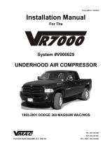
System #9028
UNDERHOOD AIR COMPRESSOR
TEL: 250-754-6997
FAX: 250-754-6972
TOLL FREE: 800-738-8622
1333 KIPP ROAD, NANAIMO, B.C. V9X 1R3
DOCUMENT 19281
1990-1996 GMC C5500, C6500, C7500 & C8500
CATERPILLAR 3116 W/WOAB

Installation Manual Document 19281
VR7000 Underhood Air Compressor
System Number 9028
Application: 1990-1996 GMC C5500, C6500 C7500 & C8500 CATERPILLAR 3126
W/WOAB
Publication Date: Jan 27, 2000
Publication Number: 19281
Origination Documents: #19281a - general information
#19282 - installing the compressor, regulator and oil cooler
#19283 - installing the air tank and lines
#19285- installing the throttle controller
#19284 - installing the control unit
#19286 - illustrated parts list
#19130 - warranty registration
Registered Trademarks:
VR7000, VMAC, Throttle Controller and Throttle Commander are registered trademarks
of VMAC, a division of Mangonel Corporation.
GMC, C5500, C6500, C7500 and C8500 are registered tradmarks of General Motors
Corporation.
Caterpillar 3116 is a registered trademark of Caterpillar Inc.
Loctite, Prime N’ Clean, 242 and PST are registered trademarks of Loctite Corporation.
Nylok is a registered trademark of Nylok Fastener Corporation.
Copyright 1999
The contents of this manual may not be reproduced in any form without the express written
permission of VMAC

General Information
System #9028
1990-1996 GMC C5500, C6500, C7500 & C8500
CATERPILLAR 3116 W/WOAB
UNDERHOOD AIR COMPRESSOR
DOCUMENT 19281

This symbol indicates that there is additional information or special emphasis
on a specific procedure.
This symbol indicates that there is a possibility of personal injury or damage to
the equipment if the indicated warning is not followed.
General Information
Introduction
This book provides installation instructions for:
VMAC underhood air compressor installation kit
VMAC Pneumatic Throttle Control
This kit has been designed for:
1990-1996 GMC C5500, C6500, C7500 & C8500 W/WOAB
Installation steps
The installation procedure in this manual has four main steps:
Part 1: Installing the Compressor
Part 2: Installing the Regulator, Oil Cooler, Air Tank and Lines
Part 3: Installing the Control Unit
Part 4: Installing the Pneumatic Throttle Control
Terms and symbols
This manual uses the following terms and symbols:
•OEM - Original Equipment Manufacturer
•HHCS - Hex Head Cap Screw (also called a hex bolt)
•SHCS - Socket Head Cap Screw (also called an Allen head bolt)
NOTE
WARNING
!
DOCUMENT 19281

Installation Notes
1. It is important that you complete all the installation steps before operating the system.
2. Follow all safety precautions for underhood mechanical work.
3. Use Loctite 242 or equivalent on all engine-mounted fasteners.
4. All hoses, tubes and wires which are re-routed or shifted during installation must be
secured so that they do not contact excessively hot areas or sharp edges. Where
possible, follow the routing instructions in this manual.
5. These installation instructions are intended as a general guide. In some instances, due
to variations in vehicle manufacture or if prior modifications have been made to the
vehicle, it may be necessary to carry out grinding, bending or rearranging operations
for correct fit. These operations must follow sound, standard shop practices.
6. Left and right definitions in this manual are determined when sitting in the driver’s
seat, facing forward.
7. All fasteners must be of the correct size and torqued according to the specifications
shown below. Torque specifications are in foot pounds (ft-lb).
8. The possibility exists that the primary installer may be color-blind. Always ensure
that another person confirms the color codes on the wires.
Type Grade 8 plated Class 10.9 unplated
Size In Cast or
Steel
In
Aluminum
In Cast or
Steel
In
Aluminum
3/8 48 45
7/16 77 70
1/2 117 95
M8 25 20
M10 45 40
M12 80 70
M14 145 130
DOCUMENT 19281

Ordering Parts
To order parts, contact VMAC at:
Telephone 250-754-6997
Facsimile 250-754-6972
Office Hours 8:00 AM to 4:30 PM Pacific Time
Please quote the VMAC part number, the description and the quantity.
Warranty
The VMAC warranty form is located at the back of this manual. This warranty form must be
completed and mailed or faxed to VMAC at the time of installation for any subsequent warranty
claim to be considered valid.
Changes and improvements
These products and documents are subject to changes or improvements without notice.
DOCUMENT 19281

Part 1
Installing
the Compressor,
Regulator
and
Oil Cooler
System #9028
1990-1996 GMC C5500, C6500, C7500 & C8500
CATERPILLAR 3116 W/WOAB
UNDERHOOD AIR COMPRESSOR
DOCUMENT 19282

Part 1: Installing the Compressor, Regulator and Oil
Cooler
1.1 Preparing for installation
1. Drain the coolant.
2. Remove both fender inserts.
3. Remove the radiator stabilizer bar from the driver’s side of the truck.
4. Loosen the OEM clamps on both ends of the intercooler tube, remove all retaining fasteners
and remove the intercooler tube from the engine. This tube will be modified and installed in
the final steps.
5. Remove the coolant expansion bottle.
6. Remove the upper radiator hose and support bracket.
7. Remove the fan from the engine.
8. Remove the fan shroud.
9. Loosen both clamps on the lower radiator hose, but only remove the end that is attached to
the engine.
10. Remove the harmonic balancer.
11. Remove and discard the fastener from the retainer which holds the electrical harness in
place on the top front driver’s side of the timing cover casting.
12. Similarly, remove but keep the hose retainer from the front of the timing cover casting, as the
compressor mounting bracket must be fitted behind the hoses.
13. Clean the engine block in the area where the compressor bracket will be mounted to ensure
that it mounts properly. If there is any contamination behind the bracket, the pulleys may
not line up correctly.
1.2 Installing the bracket and compressor
1. Remove the idler and tensioner from the VR7000 mounting bracket (Figure 1).
2. Shift the electrical harness so that it will be behind the VR7000 bracket when the bracket is
placed on the engine.
DOCUMENT 19282
NOTE
Check the engine to see if there is an oil filler tube on the timing cover. If the engine is
equipped with a filler tube, you will have to remove the tube assembly and replace it with
the VR7000 cover plate (part #32096).

DOCUMENT 19282
Figure 1
Figure 2
4. Install the idler on the VR7000 mounting bracket. Use Loctite and torque the M12 hex
head cap screw to 80 ft-lbs.
3. Fasten the compressor bracket to the engine block (Figure 2) using five (5) 10 x 30 mm hex
head cap screws and 7/16” flat washers. Use Loctite and torque them to 45 ft-lb. Fasten
the hose retainer back in place using the mounting bolt behind the tensioner (Figure 3).
Make sure that the hose does not interfere with any moving parts.
Install the VR7000 Bracket
Using these Five Holes
Tensioner Mounting Cap Screw
And Washer
Idler Mounting Cap Screw
Mount Bracket Here
Using 10 x 30 mm HHCS

DOCUMENT 19282
5. Install the tensioner on the VR7000 mounting bracket. Use Loctite and torque the M12
hex head cap screw to 80 ft-lb.
6. Place the compressor on the mounting bracket (Figure 3). Apply Loctite to the three (3)
8mm nuts. Install the washers and nuts and torque them to 25 ft-lbs.
Figure 3
7. Place the VR7000 crankshaft pulley in place on the end of the crankshaft and line up the
holes with those in the crankshaft.
8. Place the OEM harmonic balancer over the VR7000 pulley. Apply Loctite to the eight (8)
10 x 60 mm supplied hex head cap screws. Place the 3/8” flat washers over the bolts,
thread them in snug and then torque to 45 ft-lbs.
9. Install the VR7000 belt. Figure 4 shows the correct belt routing.
Figure 4
VR7000 Crankshaft
Pulley
VR7000 Idler
VR7000 Adjuster
VR7000 Compressor
Fasten the Hose
Clip Outside the
VR7000 Bracket
at This Location

DOCUMENT 19282
1.4 Installing the oil cooler
1. Fasten the oil cooler on the outside of the frame rail on the passenger side of the truck.
Figure 6 shows the location of the mounting holes on the frame.
2. Use three (3) 3/8” x 11/2” hex head cap screws, 3/8” flat washers and 3/8” Nylock nuts.
Torque them to 45 ft-lb.
1.3 Installing the regulator
1. Remove the two (2) OEM hex head cap screws from the right front side of the cylinder
head and install the regulator/throttle controller bracket assembly (Figure 5) using the OEM
fasteners.
2. Tighten the OEM hex head cap screws and make sure that the cap screws holding the
regulator assembly and throttle controller are also tight.
Figure 5 shows the bracket installed without any components and with the regulator and
throttle controller in place.
Figure 5
10. Remove the six (6) 5/16” NC cap screws holding the fan on the viscous coupling and install
the VR7000 fan spacer ring (part# 34039). Install the six (6) cap screws and tighten them.
11. Install the fan spacer (part# 34025) on the fan pulley and install the fan blades. Make sure
to install the fan shroud at the same time. Tighten the spacer and fan nut.

DOCUMENT 19282
Mount The Cooler Using These Three Holes
Figure 6
Hose Connection
To Engine Block
Using OEM Hose
Mounting Holes For
3/8" x 1-1/2" HHCS
Hose Connection
To Lower Radiator
Fitting
Figure 7
3. Place the OEM lower radiator hose (with hose clamps installed) onto the forward fitting of
the cooler (Figure 7) and the fitting on the engine.
4. Rotate the OEM hose as necessary to ensure that it clears all moving parts. Tighten the
clamps.

5. Install the 14” green stripe straight coolant hose (part #17236) between the rear cooler
fitting and the lower radiator fitting (complete with hose clamps). Tighten the clamps.
Figure 8 shows the tank installed on the frame.
6. Install the fan shroud and the fan.
7. Install the coolant expansion bottle.
8. Fill the cooling system with the OEM recommended coolant to the correct level.
DOCUMENT 19282
When operating the engine for the first time following installation, be sure to allow the
engine to reach full operating temperature and ensure that the cooling system level is
correct. Failure to do so could result in an overheat condition and possible engine
damage.
Figure 8
WARNING
!

Part 2
Installing the
Air Tank and Lines
System #9028
1990-1996 GMC C5500, C6500, C7500 & C8500
CATERPILLAR 3116 W/WOAB
UNDERHOOD AIR COMPRESSOR
DOCUMENT 19283

Part 2: Installing the Air Tank and Lines
2.1 Installing the tank mounts and the tank
1. Install the tank brackets on the inside of the frame, between the center crossmembers on the
driver’s side of the truck using four (4) 1/2” x 18” threaded rod, eight (8) 1/2” flat washers
and eight (8) 1/2” Nylok nuts.
2. Install the front air tank mounting bracket approximately 2” - 3” behind the forward
crossmember (Figure 9).
3. Install the rear air tank mounting bracket approximately 8” in front of the rear crossmember
(Figure 9).
4. Install the air tank into the brackets and install the supplied hex head cap screws, washers
and nuts in the tank clamp straps.
5. Position the air tank in the brackets so that the air outlet on the rear of the tank is
approximately 1” from the rear crossmember.
6. Rotate the tank until it is aligned as shown in Figure 10. Tighten the tank clamp straps onto
the tank.
Figure 9
This alignment is extremely important. Improper installation can result in damage to the
equipment, personal injury or death.
DOCUMENT 19283
FRONT
Approximately 8 Approximately
2” - 3”
Tank Brackets (part #12178)
Two Center Crossmembers
NOTE
Make sure that the rear tank bracket is positioned so that it does not clamp over the weld
on the back of the air tank.
WARNING
!

Figure 10
2.2 Connecting the air and oil lines
1. Figure 10 shows the locations of all lines at the air tank. Use Figure 10 to locate the correct
line fittings on the tank and the individual diagrams shown with each step for the correct
location, size and part number of each line.
This procedure will follow the installation of each individual line, show the location
on each component and describe the complete process.
2. Route all lines so that they are clear of moving parts. Secure all lines using the
appropriate tie-wrap or chassis clip to keep them in place. Do not allow lines to
contact hot engine components or exhaust components. Stainless steel tie clips are
provided for hot oil hoses or for extra strength securing.
3. Connect the 3/4” x 132” main air line (part #17260) to the compressor fitting (Figure 11) and
to the air tank at location 1 (Figure 10).
4. Connect the 1/4” x 145” pressure control line (part #17264) between the tank at position 2
(Figure 10) and the regulator (Figure 12).
The lines must be installed in the correct locations or the system will not function
properly. In addition, a hazardous situation may develop from oil spray, potential
fire or explosion.
OIL LEVEL
(check cold)
MAX
ADD
THIS
WAY
UP
IMPORTANT
UP
Check Oil
Level Here
1
2
3
4
3/4 JIC Main Air Line
1/4 SAE Pressure Control Line
5/16 SAE Oil Scavenge Line
1/2 SAE Oil Return Line
DOCUMENT 19283
WARNING
!
WARNING
!
Keep the VR7000 lines clear of all OEM hoses, as motion of the lines due to changes
in pressure can cause rubbing, resulting in rapid abrasion and wear of all lines. If you
are grouping the VR7000 lines, wrap the individual lines with rubber insulating material
to prevent damage.

Main Air Line 3/4" x 132"
Part #17260
Pressure Control Line
1/4" x 145" Part #17264
DOCUMENT 19283
Figure 11
Figure 12
Main Air Line 3/4" x 132"
Part #17260

Main Air Line 3/4" x 132"
Part #17260
Pressure Control Line
1/4" x 145" Part #17264
Scavenge Line 5/16" x 141"
Part #17263
DOCUMENT 19283
5. Connect the 5/16” x 141” scavenge line (part #17263) to the fitting on the compressor
control valve (Figure 13) and to the air tank at location 3 (Figure 10). Figure 14 shows the
line routing from the tank through the frame members.
Figure 13
Figure 14

Main Air Line 3/4" x 132"
Part #17260
Pressure Control Line
1/4" x 145" Part #17264
Scavenge Line 5/16" x 141"
Part #17263
Oil Return Line - Cooler to Compressor
1/2" x 68" Part #17262
Main Air Line 3/4" x 132"
Part #17260
Pressure Control Line
1/4" x 145" Part #17264
Scavenge Line 5/16" x 141"
Part #17263
Oil Return Line - Tank to Cooler
1/2" x 194" Part #17261
Oil Return Line - Cooler to Compressor
1/2" x 68" Part #17262
DOCUMENT 19283
6. Connect the 1/2” x 68” cooler to compressor oil return line (part #17262) to the fitting on the
bottom of the compressor and to the rearward cooler fitting (Figure 15). Route this line
under the engine, through the front cross-member (Figure 17).
Figure 15
7. Connect the 1/2” x 194” tank to cooler oil return line (part #17261) to the forward cooler
fitting (Figure 16) to the tank fitting at location 4 (Figure 10). Follow the same route as with
the previous line (Figure 17).
Figure 16

DOCUMENT 19283
Figure 17
/