Page is loading ...

HONEYWELL
CLASS “A” COMBINATION VALVES
VQ400M-Series
ISTR0023 1712RA
1
VQ400M SERIES
CLASS “A” COMBINATION VALVES
INSTRUCTION SHEET
APPLICATION
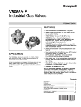
Figure 1 VQ420M & VQ425M
Figure 2 VQ440M & VQ450M
The VQ400M Series class “A” safety combination
valves are used for control and regulation of
gaseous fluids in gas power burners, atmospheric
gas boilers, melting furnaces, incinerators and
other gas consuming appliances.
The VQ400M offers flexibility to mount accessories
like valve-position indicator, pressure indication
switches, vent-valves or by-pass valves at several
positions at the gas valve, whenever, wherever.
These combination valves are available in two body
sizes:
Small model
o VQ420
o VQ425
Large model
o VQ440
o VQ450
All models are connected at suitable sized gas
pipes by flange kits which can be ordered
separately in several sizes.

HONEYWELL
CLASS “A” COMBINATION VALVES
VQ400M-Series
ISTR0023 1712RA
2
CONTENTS
VQ400M SERIES ............................................................. 1
CLASS “A” COMBINATION VALVES .......................... 1
APPLICATION .................................................................. 1
Contents ........................................................................... 2
FEATURES....................................................................... 2
Dimensions ................................................................... 2
Pipe sizes ...................................................................... 2
Connections .................................................................. 3
Ambient temperature range .......................................... 3
Enclosure ...................................................................... 3
Power consumption ...................................................... 3
PERFORMANCE CHARACTERISTICS .......................... 3
Opening time ................................................................ 3
Closing time .................................................................. 3
Maximum working frequency ........................................ 4
Operational voltage range ............................................ 4
INSTALLATION ................................................................ 4
IMPORTANT ................................................................. 4
WARNING ..................................................................... 4
Maintenance and service .............................................. 4
Mounting position .......................................................... 4
Mounting location .......................................................... 4
Main gas connection flanged valves ............................ 5
WARNING!.................................................................... 5
Electrical connection ..................................................... 5
WARNING ..................................................................... 5
Wiring PG11 ................................................................. 5
Wiring Din plug ............................................................. 6
ADJUSTMENTS AND FINAL CHECKOUT ..................... 6
CAUTION ...................................................................... 6
2nd main valve fast opening .......................................... 6
2nd main valve slow opening ......................................... 7
IMPORTANT ................................................................. 7
Final checkout of the installation .................................. 8
INSTALLATION of optional valves ................................... 8
WARNING ..................................................................... 8
Replacement of parts ....................................................... 8
Warning ......................................................................... 8
Recommended accessories ............................................. 8
APPROVALS .................................................................. 10
Declaration of Conformity ........... Error! Bookmark not
defined.
FEATURES
Dimensions
Main dimensions of the models are given at
installation drawings:
Table 1 Overview of installation drawings.
Model Installation drawing
VQ420M INST0171
VQ425M INST0172
VQ440M INST0169
VQ450M INST0170
Installation drawings are available in Honeywell
documentation centre “HotDocs” and can be
supplied digitally on request through Honeywell
sales representative.
Pipe sizes
For connecting with several pipe sizes it is
recommended to mount Honeywell flange kits
which can be ordered separately as indicated
below.
Table 2 Overview of recommended pipe sizes.
Gas valve Recommended pipe size Option
VQ420M ½” 1
VQ420M ¾” 2
VQ425M 1”
VQ440M 1 ¼” 1
VQ440M 1 ½” 2
VQ450M 2”
Recommended flanges for each model to be
mounted are given in table 10 and table 11.

HONEYWELL
CLASS “A” COMBINATION VALVES
VQ400M-Series
ISTR0023 1712RA
3
Connections
As shown in the figure below, VQ400M is provided
with plugs and flanges giving flexibility to customize
this combination valve with Honeywell accessories.
Ambient temperature range
VQ400M is designed to operate in ambient
temperature levels between: -15 ... 60 °C
Enclosure
IP54 in combination with PG11 connection.
IP65 in combination with DIN-plug connection.
Power consumption
Honeywell provides VQ400M with coils that suit
demands of specified inlet pressure levels. An
overview of power consumption for different
applications is given in the table below.
Table 3 Power consumption of each VQ400M main valve for
360 mbar applications.
115V 230V
VQ420M 14 14
VQ425M 18 20
VQ440M 41 48
VQ450M 65 60
PERFORMANCE
CHARACTERISTICS
Opening time
The first valve (V1) opens in less than 1 second.
The second valve (V2) can be either a fast opening
valve which opens in less than 1 second or a
characterized opening valve which is adjustable
from 1 up to 30 seconds, at rated capacity.
The opening characteristic is factory set at
approximately 6 seconds at the following
conditions:
measured at 80 % of rated capacity
30 mbar supply pressure
nominal voltage
20 °C
2,5 mbar pressure drop
no step pressure
Due to the influence of ambient temperature (-15 ...
60 °C) the adjusted opening time of 6 seconds
measured at 80% of adjusted flow rate can vary +/-
4 seconds.
Closing time
Less than 1 second for both valves.
Plugs for mounting:
pressure tap
Valve proving
system
Pressure switches
Plugs for connecting:
By pass valve
Internal or external
pilot valve
Vent valve
Flange connection V2
In the bottom plate two plugs are
available for mounting Closed
position indicator
Outlet flange
Inlet flange
Flange connection V1
Plug for mounting
p
ress
u
re t
ap

HONEYWELL
CLASS “A” COMBINATION VALVES
VQ400M-Series
ISTR0023 1712RA
4
Maximum working frequency
VQ400M is equipped for maximal working
frequency of one cycle per minute.
Operational voltage range
The combination gas valve will function satisfactory
between 85% and 110% of the rated voltage.
INSTALLATION
IMPORTANT
1. Read these instructions carefully. Failure to
follow the instructions could damage the
product or cause a hazardous condition.
2. Check the ratings given in the instructions
and on the product to make sure the
product is suitable for your application.
3. The installation has to be carried out by
qualified personnel only.
4. Carry out a thorough checkout when
installation is completed.
WARNING
Turn off gas supply before installation.
Disconnect power supply to the valve
actuator before beginning the installation to
prevent electrical shock and damage to the
equipment.
Do not remove the seal over valve inlet and
outlet until ready to connect piping.
The valve must be installed so that the
arrow on the valve points in the direction of
the gas flow (gas pressure helps to close
the valve).
Maintenance and service
The designed lifetime* of this product is 10 years,
based on date code, according to:
a) the standard EN 126
b) the table on designed lifetime as stated on
the Afecor website http://www.afecor.org/
We cannot assume that the product can be safely
used beyond the mentioned designed lifetime. This
lifetime is based on use of the control according
manufacturer’s instructions.
Regular inspection of the control by authorized
personnel in accordance with guidelines of the
appliance manufacturer is required.
After reaching the designed lifetime the product has
to be replaced by authorized personnel.
Note: * Warranty as opposed to designed lifetime is
described in the delivery terms.
Mounting position
The gas valve can be mounted in vertical position
with the coils at top side. The gas valve can be
mounted plus or minus 90 degrees from the
vertical.
Mounting location
The distance between the gas valve and the
wall/ground must be at least 30 mm.

HONEYWELL
CLASS “A” COMBINATION VALVES
VQ400M-Series
ISTR0023 1712RA
5
Main gas connection flanged
valves
1. Take care that dirt does not enter the gas
valve during handling.
2. Remove the flanges from the valve.
3. Use a sound taper fitting with thread
according to ISO 7-1 or new, properly
reamed pipe, free from swarf.
4. Apply a moderate amount of good quality
thread compound to the pipe for fitting only;
leaving the two end threads bare, PTFE
tape may be used as an alternative.
5. Screw the flanges onto the pipes.
6. Ensure that inlet and outlet flanges are in
line and separated from each other enough
to allow the valve to be mounted between
them without damaging the gasket.
7. Place gasket. If necessary grease it slightly
to keep it in place.
8. Mount gas valve between flanges using the
bolts for each flange.
9. Complete the electrical connections as
instructed in the electrical connection
section.
WARNING!
Tightness test after installation
Spray all pipe connections and gaskets
with a good quality gas leak detection
spray.
Start the appliance and check for bubbles.
If a leak is found in a pipe connection,
remake the joint. A gasket leak can usually
be stopped by tightening the mounting
screws, otherwise, replace the gas valve.
Electrical connection
WARNING
Switch off power supply before making
electrical connections.
All wiring must comply with local codes,
ordinances and regulations.
Use lead wire which can withstand 105 °C ambient.
The electric ON/OFF operator is provided with a
terminal block for electrical connections.
Wiring PG11
Remove screws (A)
Take off protective cover lids and gaskets (B)
Un-tighten cable support screw (C).
Prepare cable
Remove plastic outside insulation for about
50 – 75 mm.
Strip wires from plastic insulation for about
5 – 7 mm.
Place cable in cable support screw and guide wires
through the hole in the cover to the connection
block (D).
Connect wires between plates by tightening the
particular screws (D1, D2, D3).
Left: phase V1 or V2
(B)
(C)
(D)
(A)

HONEYWELL
CLASS “A” COMBINATION VALVES
VQ400M-Series
ISTR0023 1712RA
6
Middle: earth connection
Right: Neutral
For VQ420M and VQ425M is possible to make
connection between the two coils, in that case two
wires per connection might need to be connected.
Tighten cable support screw (C).
Place gasket and cover lid in position (B)
Place screws (A) and tighten screws.
Wiring Din plug
Follow the instructions supplied by the appliance
manufacturer as shown in the figures below.
Figure 3 Three pin electrical plug connector (according to
ISO 4400).
Figure 4 Connection diagram VQ400M
ADJUSTMENTS AND FINAL
CHECKOUT
The procedures described in this chapter are
related to the adjustments on the main gas valve,
pilot valve and by-pass valve. For adjustments on
the other additional functionalities (e.g. pressure
switch), refer to the included instruction sheet of the
product in question in the package.
CAUTION
Adjustments must be made by qualified
personnel only.
To ensure a safe closing of the valves, it is
essential that voltage over the terminals of
operators is reduced to 0 Volts.
2nd main valve fast opening
Figure 5 Adjusting flow rate.
Flow rate adjustment (see Fig. 6.)
1. Remove the cap screw from top of the coil.
2. Place a socket head wrench into the
adjustment nut.
3. Turn wrench counter-clockwise to increase
or clockwise to decrease flow rate.
4. Replace cap screw.

HONEYWELL
CLASS “A” COMBINATION VALVES
VQ400M-Series
ISTR0023 1712RA
7
2nd main valve slow opening
The following characteristics can be adjusted:
flow rate
step pressure
opening speed
Figure 6 Characterized opening.
IMPORTANT
To ensure a satisfactory setting of the valve the
pressure drop over the valve should be at least
10% of the supply pressure or 2.5 mbar which ever
is the greatest.
Flow rate adjustment
1. Remove the cap from top of the coil by
loosening both screws.
2. Place a wrench on the adjustment hexagon
nut.
3. Turn wrench counter-clockwise to increase
or clockwise to decrease the flow rate.
4. Replace cap on top of the coil.
Figure 7 Adjusting flow rate.
Step pressure adjustment (see fig. 9.)
1. Remove the cap from top of the coil by
loosening both screws.
2. Place a screw driver in the slot of
adjustment screw which is situated in
center of the valve.
3. Turn screw driver counter-clockwise to
increase or clockwise to decrease step
pressure.
4. Replace cap on top of the coil.
Figure 8 Adjusting step pressure.
Opening speed adjustment
1. Remove the cap from top of the coil by
loosening both screws.
2. Place screw driver in the slot of adjustment
screw which is of center line.
3. Turn screw driver counter-clockwise to
increase the opening speed and therefore
the time till full opening will decrease.
4. Turn screw driver clockwise to decrease
the opening speed and therefore the time
till full opening will increase.
5. Replace cap on top of the coil.
Figure 9 Adjusting opening speed.

HONEYWELL
CLASS “A” COMBINATION VALVES
VQ400M-Series
ISTR0023 1712RA
8
Final checkout of the installation
Set the appliance in operation after any adjustment
and observe several complete cycles to ensure that
all burner components function correctly.
INSTALLATION OF OPTIONAL
VALVES
Installation can be done by the OEM or by qualified
personnel in field.
WARNING
If additional hardware needs to be installed on field,
then installation personnel should take care, that
the main gas flow to the appliance has been
completely stopped by an upstream manual shut-
off valve prior to the installation.
Installation
1. Open the required gas flow channels by
removing the suitable plugs from the valve
body.
2. Take care that dirt can not enter the gas
valve during handling
3. Install the screw-in additional hardware as
required (vent, by-pass, external pilot
valve)
4. Please refer to the relevant instruction
sheet
REPLACEMENT OF PARTS
Warning
Take care that only qualified persons carry
out the installation of parts, accessories,
and add on components.
Follow the installation instructions included
in the package.
Check that the selected part, accessory or
add-on component is the correct one for
the application in question.
Replace old gaskets with the new ones
supplied in the package and check for
leakage when the supply is switched on
again.
After installation and/or replacement has
been completed, a gas leak test must be
carried out.
Also check the gas valve for satisfactory
operation after fitting accessories.
RECOMMENDED ACCESSORIES
There are two different series of flange kits
available. The first series of flange kits consist of: 1
flange with sealing plug, 1 O-rings and 4 screws.
Table 4 Flange kits without strainer.
Gas valve Recommended flange kit
VQ420M KTCOMB15
VQ420M KTCOMB20
VQ425M KTCOMB25
VQ440M KTCOMB32
VQ440M KTCOMB40
VQ450M KTCOMB50
The second series of flange kits consist of: 1 flange
with sealing plug or cast pressure tap, 1 strainer, 1
O-rings and 4 screws

HONEYWELL
CLASS “A” COMBINATION VALVES
VQ400M-Series
ISTR0023 1712RA
9
Table 5 Flange kits with strainer.
Gas valve Recommended flange kit
VQ420M KTCOMS15
VQ420M KTCOMS20
VQ425M KTCOMS25
VQ440M KTCOMS32
VQ440M KTCOMS40
VQ450M KTCOMS50
Table 6 Overview of recommended internal by-pass valves.
Gas valve Internal by pass valve
VQ400M VB420Xxxxx
See Honeywell documentation VB420Xxxxx KIT for
further instructions on internal by-pass valves.
Table 7 Overview of recommended external pilot valves.
Gas valve External pilot valve
VQ400M VP420Xxxxx
See Honeywell documentation VP420Xxxxx KIT for
further instructions on external pilot valves.
Table 8 Overview of recommended vent valves.
Gas valve Vent valve
VQ400M VV420Xxxxx
See Honeywell documentation VV420Xxxx KIT for
further instructions on vent valves.
Table 9 Overview of characterized opening mechanisms.
Gas valve Slow opening
mechanism
VQ400M GF050001
Table 10 Overview of recommended closed position
indication switches (CPI).
Gas valve Closed position indicator
VQ420M MS062001
VQ425M MS062501
VQ440M MS064001
VQ450M MS065001
Table 11 Honeywell fine particle filter.
Gasvalve Honeywell Filter
VQ420M HFVR050 / HFVR150
VQ425M
This filter is used to filter fine (50 or 150 µm)
particles of dirt out of gas flow.

HONEYWELL
CLASS “A” COMBINATION VALVES
VQ400M-Series
10
Honeywell
Honeywell Building Technologies
Environmental & Energy Solutions
Honeywell Technologies Sàrl
Z.A. La Pièce 16
1180 Rolle (VD) – CH:
ISTR0023 1712RA
STANDARDS AND APPROVALS
/