Page is loading ...

THANK YOU
We appreciate the trust and confidence you have placed in Home Decorators Collection through the purchase of this Silverthorne
collection electric fireplace media mantel. We strive to continually create quality products designed to enhance your home. Visit us online
to see our full line of products available for your home improvement needs. Thank you for choosing Home Decorators Collection!
USE AND CARE GUIDE
SILVERTHORNE COLLECTION: ELECTRIC FIREPLACE MEDIA MANTEL
Questions, problems, missing parts? Before returning to the store,
call Home Decorators Collection Customer Service
8 a.m. - 6 p.m., EST, Monday-Friday
1-800-986-3460
HOMEDEPOT.COM/HOMEDECORATORS
Item # 1000-050-887
# 658-383
Model # MTVSC2513SE-2
# MTVSC2513SCH
# MFB25WSC-1

2
Table of Contents ....................................2
Safety Information ...................................2
Warranty ..........................................3
Pre-Assembly ......................................4
Planning Assembly .................................4
Tools Required ....................................4
Hardware Included .................................4
Package Contents ..................................5
Grounding Instructions ..............................6
Determining the Mounting Location ....................6
Firebox Specifications ..............................6
Electrical Connection ...............................6
Glass information ..................................6
Assembly ..........................................7
Operation .........................................12
Care and Cleaning ..................................14
Service Parts ......................................15
1. Read all instructions before using this fireplace.
2. Always unplug the fireplace when not in use.
3. Do not operate any fireplace with a damaged cord or plug
or after the fireplace malfunctions, has been dropped, or is
damaged in any manner. Return the fireplace to an authorized
service facility for examination, electrical or mechanical
adjustment, or repair.
4. Do not use outdoors.
5. This fireplace is not intended for use in bathrooms, laundry
areas, and similar indoor locations. Never locate the fireplace
where it may fall into a bathtub or other water container.
6. Do not run the power cord under carpeting. Do not cover the
power cord with items such as throw rugs or runners. Arrange
the power cord away from traffic areas to ensure that it is not
tripped over.
7. To disconnect the fireplace, turn the controls to the off position,
and remove the plug from the outlet.
8. Connect to properly grounded outlets only.
9. Use this fireplace only as described in this manual. Any other
use not recommended by the manufacturer may cause fire,
electrical shock, or injury to persons.
10. Avoid the use of an extension cord because the extension cord
may overheat and cause a risk of fire. However, if you have to
use an extension cord, the cord shall be No.14 gauge minimum
size and rated not less than 1875 watts.
11. This media mantel is intended for use with up to 60 in. plasma /
LCD televisions with a maximum load of 110 lb. (50 kg). Use with
other products or products heavier than the maximum weight
indicated may result in instability, causing possible injury.
12. Flat panel televisions with base supports should be placed
squarely in the center of the stand with no overhang on any side.
13. Maximum load on all shelves is 30 lbs. (13.6 kg)
Table of Contents
Safety Information
WARNING: This fireplace is hot when in use. To avoid
burns, do not let bare skin touch hot surfaces. If provided,
use handles when moving this fireplace. Keep combustible
materials, such as furniture, pillows, bedding, papers,
clothes, and curtains at least 3 ft (0.9 meters) from the front
of the fireplace and keep them away from the sides and
rear.
CAUTION: Extreme caution is necessary when any fireplace
is used by or near children or invalids and whenever the
heater is left operating and unattended.
CAUTION: Do not insert or allow foreign objects to enter
any ventilation or exhaust openings, as this may cause an
electric shock or fire, or damage to the fireplace.
CAUTION: When using electrical appliances, basic
precautions should always be followed to reduce the risk of
fire, electrical shock, and injury to persons.
CAUTION: To prevent a possible fire, do not block firebox air
intakes or the exhaust in any manner. Do not operate the
fireplace on soft surfaces, like a bed, where openings may
become blocked.
CAUTION: A fireplace has hot and arching or sparking
parts inside. Do not use in areas where gasoline, paint, or
flammable liquids are used or stored.
FOR YOUR SAFETY: Service must be performed by
qualified/authorized service personnel only.

3
HOMEDEPOT.COM/HOMEDECORATORS
Please contact 1-800-986-3460 for further assistance
LIMITED WARRANTY
The supplier warrants this product to be free from defects in material and workmanship, under normal use and service, for one (1) year
(1 year limited parts) from the date of purchase.
All warranty repairs must be pre-authorized by the supplier. The supplier will, at its option, replace or repair free of charge any defective
part, which the purchaser shall notify their distributor or the supplier within the warranty period. The obligation of the supplier under this
warranty, is expressly limited to such replacement or repairs.
The provisions of this limited warranty shall not apply to the following:
□ Accidents
□ Unauthorized repairs or alterations
□ Normal maintenance
□ Changes made to other units manufactured after this fireplace insert was manufactured
□ Incidental damages caused by failure of the fireplace insert, such as inconvenience or loss of use
□ Improper installation
The provisions of this limited warranty shall not apply to deterioration due to wear and exposure beyond one (1) year from the date of
purchase on electrical component and circuit boards (light bulbs excluded).
The supplier Limited Warranty is void unless the following conditions are adhered to:
□ Warranty registration must be completed and returned to the supplier.
□ All warranty repairs must be pre authorized by the supplier’s repair facility.
□ The supplier reserves the right to inspect defective parts that have been replaced under warranty. The distributor is expected to hold
defective parts for 60 days.
□ Only parts and accessories and other material, available through the supplier, are to be used in the performance of warranty service.
□ Purchasers are responsible for presenting/notifying their distributor as soon as a problem exists. The warranty repairs should be
completed in a reasonable amount of time from the date of authorization. Not to exceed 30 days past notification.
This limited warranty is expressly in lieu of any other expressed or implied warranty, including any implied warranty or merchantability or
fitness for a particular purpose and of any obligations or liabilities on the supplier which neither assumes nor authorizes any other person to
assume for it any other liability in connection with the fireplace insert manufactured by it.
The warranty is null and void if used in commercial or industrial applications.
Warranty

4
PLANNING ASSEMBLY
Before you begin assembly, locate the instructions and hardware. Compare all parts with the Hardware Included and Package Contents
lists. Be sure you have all the parts and can identify them. A helping hand is always good. Assemble your mantel with an adult assistant if
possible. Some pieces are heavy and will need to be held by a helper. Assembly time will take approximately 30-60 minutes.
Before assembly, use scissors to unwrap the parts from the packaging. Do not use a box cutter or exacto-knife, as you may cut into the
mantel pieces inside the box and damage the finish. Check for the red hardware bag located inside the packaging. Do not discard any
pieces. Use an appropriate screwdriver to insert and tighten all screws.
TOOLS REqUIREd
Safety goggles
Phillips
screwdriver
HARdwARE INCLUdEd
NOTE: Hardware not shown to actual size.
Part description quantity Part description quantity
AA Cam Lock Dowel 24
JJ Small Screws 42
BB Cam Lock 24
KK Medium Screws 1
CC Wood Dowel 24
LL Washer 2
DD Bolt 2
MM Door Stop 2
EE Long Screws 1
NN Nylon Strap 1
FF Screw 24
OO Anchor Screw 1
GG Hinge 4
PP Screws for Firebox Insert 2
HH Knob 4
QQ Firebox Trim Screw 4
II Shelf Support 8
Pre-Assembly
DDCCBBAA EE
FF GG HH
KKJJ
II
LL MM NN OO Touch Up
Pen
PP
QQ

5
HOMEDEPOT.COM/HOMEDECORATORS
Please contact 1-800-986-3460 for further assistance
PACkAGE CONTENTS
Part Description Quantity
A Top 1
B Base 1
C Fixed Shelf 1
D Side Panel 2
E Left Interior Panel 1
F Right Interior Panel 1
G Upper Side Panel 2
H Left Door 1
I Right Door 1
Part Description Quantity
J Shelves 2
K Back Panel 2
L Upper Back Panel 1
M Firebox Brace 1
N Remote Control 1
O Batteries 2
P Firebox Insert 1
Q Firebox Trim 1
Pre-Assembly (continued)
P
O
Q
N
M

6
GROUNDING INSTRUCTIONS
This heater is for use with 120V power sources. The cord has a three-blade, grounding-type
plug. An adapter is available for connecting three-blade grounding-type plugs to two-slot
receptacles. The green grounding lug extending from the adapter must be connected to a
permanent ground, such as a properly grounded outlet box. The adapter should not be used if
a three-slot grounded receptacle is available.
DETERMINING THE MOUNTING LOCATION
When choosing a location for your new fireplace, ensure the general instructions are followed.
For the best effect, install the fireplace out of direct sunlight. It is safe to set the fireplace
insert close to non-combustibles.
WARNING: Do not store or use gasoline or other flammable vapors or liquids in the vicinity of this or any other appliance.
FIREBOX SPECIFICATIONS
ELECTRICAL CONNECTION
A 15 Amp, 120 Volt, 60 Hz circuit with a properly grounded outlet is required to operate this appliance. Preferably, the fireplace insert
will be on a dedicated circuit, as other appliances on the same circuit may cause the circuit breaker to trip or the fuse to blow when
the heater is in operation. The unit comes standard with a 6 ft (1.8 m) long 3-wire cord, exiting out the back of the fireplace insert. Plan
the installation to avoid the use of an extension cord. If an extension cord must be used, it must be a minimum 14-gauge, 3-wire with
grounding type plug and connector, and must be rated not less than 1875 watts. The extension cord shall not be more than 20 ft (6 m) in
length.
WARNING: Electrical outlet wiring must comply with local building codes and other applicable regulations to reduce
the risk of fire, electrical shock, and injury to persons.
WARNING: Do not use this fireplace insert if any part of it has been under water. Immediately call a qualified service technician to inspect the
firebox and replace any part of the electrical system which has been under water.
GLASS INFORMATION
1. Under no circumstances should this product be operated with a broken or chipped glass panel.
2. Do not strike or slam the glass.
3. Do not use abrasive cleansers to clean the glass.
4. This product uses tempered glass. Replacement of the glass supplied by the manufacturer should be done by qualified/authorized
service personnel only.
Pre-Assembly (continued)
Model No. MFB25WSC-1
Dimensions W x D x H 25 in. x 10.4 in. x 18.5 in. (63.3 cm x 26.5 cm x 47 cm)
Net Weight / Gross Weight 27.7 lbs / 31 lbs (12.6 kg / 14.1 kg)
Voltage 120V
Frequency 60 Hz
Watts / Amps 1400 W / 11.6 A
Fireplace Rating 1400 W / 4777 BTUs
Adapter
Grounding Lug
Cover of Grounded Outlet Box
Grounding Pin
Cover of Grounded Outlet Box
Metal
Screw

7
HOMEDEPOT.COM/HOMEDECORATORS
Please contact 1-800-986-3460 for further assistance
Assembly
1
Preparing the base
□ Locate the base (B) and place on a soft surface to
protect the finish.
□ Insert eight cam lock dowels (AA) into the threaded
holes. Make sure the threaded side is facing down
so you can insert and tighten each cam lock dowel
(AA) into each threaded hole in the top of base (B).
Do not overtighten the cam lock dowels (AA).
□ Insert eight wood dowels (CC) into the unthreaded
holes into the top of the base (B).
2
Assembling the panels
□ Locate the side panels (D), left interior panel (E)
and right interior panel (F).
□ Line up and insert the cam lock dowels (AA) on the
base (B) into the holes of the exterior panels (D).
□ Push the panels together until flush with the top of
the base (B). Tighten the cam locks (BB) by turning
clockwise. Do not strip the cam locks by over
tightening.
□ Repeat the steps for the second side panel (D), left
interior panel (E), and right interior panel (F).
□ Insert eight wood dowels (CC) into the holes on the
top of each panel. Two wood dowels per panel.
AA
CC
3
Preparing the fixed shelf
□ Locate the fixed shelf (C) and place on a soft surface
bottom side up to protect the finish.
□ Insert eight cam lock dowels (AA) into the threaded holes.
Make sure the threaded side is facing down so you can
insert and tighten each cam lock dowel (AA) into each
threaded hole in the bottom of the fixed shelf (C). Do not
overtighten the cam lock dowels (AA).
□ Locate the two door stoppers (MM). Align the holes in
the door stoppers (MM) with the pre-drilled holes in the
bottom of the fixed shelf (C). Make sure the flange is
facing the front of the shelf.
□ Fasten the door stoppers (MM) to the fixed shelf (C) using
four small screws (JJ).
CC
BB
AA
JJ
MM

8
Assembly (continued)
4
Assembling the fixed shelf
□ Turn the fixed shelf (C) upright.
□ With a partner, align the cam lock dowels (AA)
with the holes in the top of each panel (D, E,
F). It is easier to start at one side and align the
holes and wooden dowels (CC) in each panel
one at a time.
□ Push the fixed shelf (C) until flush with the top
of the panels (D, E, F). Insert eight cam locks
into the top holes of panels (D, E, F).
□ Tighten the cam locks (BB) by turning
clockwise. Do not strip the cam locks by over
tightening.
□ Insert four wood dowels (CC) into the holes on
the top of the fixed shelf (C).
5
Assembling the upper side
panels
□ Locate the two upper side panels (G). Align
the cam lock dowels (AA) and wood dowels
(CC) with holes in the bottom of the upper side
panels.
□ Push the upper side panels (G) until flush with
the top of the fixed shelf (C). Insert four cam
locks into the holes of the upper side panels (G).
□ Tighten the cam locks (BB) by turning clockwise.
Do not strip the cam locks by over tightening.
□ Insert four wood dowels (CC) into the holes on
the top of the upper side panels (G).
6
Preparing the top
□ Locate the top (A) and place on a soft surface,
bottom side up, to protect the finish.
□ Insert four cam dowels (AA) into the threaded
holes. Make sure the threaded side is facing down
so you can insert and tighten each cam lock dowel
(AA) into each threaded hole in the bottom of the
fixed shelf (C). Do not overtighten the cam lock
dowels (AA).
□ Insert four cam lock dowels (AA) into the threaded holes. Make sure the threaded side is facing down so you can insert and tighten
each cam lock dowel (AA) into each threaded hole in top of the fixed shelf (C). Do not overtighten the cam lock dowels (AA).
AA
AA
CC
BB
CC
BB
AA
AA

9
HOMEDEPOT.COM/HOMEDECORATORS
Please contact 1-800-986-3460 for further assistance
Assembly (continued)
7
Assembling the top
□ Locate the top (A) and place on a soft surface,
bottom side up, to protect the finish.
□ Insert four cam dowels (AA) into the threaded
holes. Make sure the threaded side is facing down
so you can insert and tighten each cam lock dowel
(AA) into each threaded hole in bottom of fixed
shelf (C). Do not overtighten the cam lock dowels
(AA).
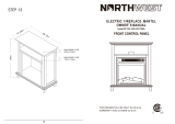
8
Assembling the back panels
□ Locate the upper back panel (L) and lower back
panels (K).
□ Fasten the back panels (K, L) to the assembled unit
using 38 smalls screws (JJ). Do not over tighten
the screws.
9
Installing the shelves
□ Locate the two shelves (J) and set aside.
□ Insert shelf supports (II) into the desired hole height. Make
sure that the supports (II) are in same hole for each shelf
for stability.
□ Insert shelves (J) into the side storage areas. Tilting the
shelves on a slight angle while inserting will help clear
the opening.
AA
BB
JJ
II

10
Assembly (continued)
10
Preparing the door for installation
□ Locate the right door (I) and left door (H) and place on a soft surface to
protect the finish.
□ Place the open side of each hinge (GG) into the recessed area on
each of the right door (I) and left door (H). Insert and tighten two
hinge screws (FF) into each of the two holes in each hinge. Do not
overtighten screws.
11
Installing the door
□ Line up and insert the other end of the door hinges (GG) into the
recessions in the left and right side exterior panels (D) of the
assembled mantel.
□ Secure the door hinges (GG) to the mantle using eight screws
(FF).
□ Secure the handles (HH) to the left and right doors (H,I) by
inserting the handle bolts (DD) through the left and right doors
(H,I) and tighten until snug.
L
12
Inserting the firebox
□ Attach the top trim (Q) (optional) with the 3
screws (QQ) provided (spare included).
□ Insert the firebox insert (P) into the mantel from the rear. Be
very careful not to scratch the base (C).
□ Viewing from the front of the mantel, ensure that the firebox
insert (P) is in the center of the opening.
FF
GG
GG
FF
HH
DD
P
x3
QQ
Q
1
2

11
HOMEDEPOT.COM/HOMEDECORATORS
Please contact 1-800-986-3460 for further assistance
Assembly (continued)
13
Securing the firebox
□ Locate the firebox brace (M) and place it snuggly behind the
firebox insert (P) to hold it in position. Do not cover any air
venting.
□ Insert two large flat head screws (PP) through the holes in the
firebox brace (M) and into the base (C). Tighten until secure.
14
Attaching the anti-tip device to the mantel
□ Push one medium screw (KK) through one washer (LL) and fasten the
nylon strap (NN) to the back of the top (A).
15
Attaching the anti-tip device to a wall
□ Determine the location of the fireplace and mark the location on the
wall for the nylon strap (NN) screw holes. Using a drill or screwdriver,
make the holes in the wall where marked.
□ If you are attaching to drywall or plaster, insert a wall anchor (OO) into
the hole in the wall.
□ Push one large screw (EE) through one washer (LL) and fasten the
nylon strap (NN) to the wall.
LL
KK
NN
NN
LL
OO
EE
PP
M
WARNING: This product is only a deterrent. It is not a substitute for
proper adult supervision.

12
2
Using the manual control
□ To turn the firebox on and off, press the main power
switch (5).
□ Press the power button (1) on the control panel (P). The
flame effect will turn on.
□ Press the flame “+” or flame “–” button (2) to achieve the
desired effect (no heat).
□ Press the heat button (4) once for “low” or twice for “high”
to achieve the desired level. Press the button a third time
to turn the heating cycle off.
□ To illuminate the firebox, press the light button (3).
1
2
3 4
Operation
1 3 2 2 4 5
P
N
NOTE: The flame effect is always active when the heating
cycle is operational.
NOTE: The main power button (5) on the firebox must be
turned on for the remote control to function.
NOTE: The flame effect is always active when the heating
cycle is operational.
1
Using the remote control
□ Press the power button (1) on the remote control (N). The
flame effect will turn on.
□ Press the flame “+” or flame “–” button (2) to achieve the
desired effect (no heat).
□ Press the heat button (4) once for “low” or twice for “high”
to achieve the desired level. Press the button a third time
to turn the heating cycle off.
□ To illuminate the firebox, press the light button (3).

13
HOMEDEPOT.COM/HOMEDECORATORS
Please contact 1-800-986-3460 for further assistance
1
Removing the access panels
□ Turn the firebox master power “on/off” switch to the “off”
position, (located behind the front access panel).
□ Pull the mantel away from the wall, as you need to access
the back of the firebox. Unplug the firebox from the power
outlet.
□ Let the firebox insert cool if it has been operating.
□ Looking at the back of the firebox, locate the two small
access panels.
□ Remove the screws in each panel using a Phillips or
flathead screwdriver. Pull the access panel toward you. The
light bulbs are attached to a slide, which will bring them to
the edge of the firebox for your convenience.
2
Replacing the bulbs
□ Carefully remove the burnt light bulb. This may require
holding the light socket with one hand while unscrewing
the light bulb with the other hand.
□ Install the new light bulbs.
□ Push in the slides and replace the access panels.
□ Insert and tighten the screws in each panel that were
removed.
□ Plug the firebox into the power outlet and return your
mantel to its original position against the wall.
□ Turn the firebox master power “on/off” switch to the “on”
position and press the power button (1) on the control
panel (P). Check that the replacement bulbs are working.
WARNING: Do not exceed 40 Watts per bulb. Use of
higher rated light bulbs may cause overheating and result
in a fire, causing property damage, personal injury, or loss
of life.
NOTE: This fireplace insert uses two clear 120 Volt, 40 Watt,
E-12 socket base light bulbs (small base, chandelier candle
type bulbs). The light bulbs are located at the bottom of the
unit. You can change the light bulbs from the back of the
firebox. For convenience, if one of the light bulbs burns out, it
may be easier to replace all of the light bulbs at the
same time.
ACCESS PANELS
Maintenance
1 3 2 2 4 5
P

14
□ Any repairs to this appliance should be carried out by qualified/authorized service personnel only.
□ Dust your fireplace mantel regularly with a soft, non-lint producing cloth or household dusting product.
□ Under no circumstances should this appliance be modified. Parts having to be removed for servicing must be replaced with original
OEM (original equipment manufacturers) parts only.
□ Clean this firebox with a damp cloth (water) only.
□ Unplug this firebox when not in use.
□ Under no circumstances should this product be operated with a broken or chipped glass panel.
□ Do not strike or slam the glass.
□ Do not use abrasive cleansers to clean the glass.
□ This product uses tempered glass. Replacement of the glass supplied by the manufacturer should be done by qualified/authorized
service personnel only.
Care and Cleaning
IMPORTANT: Always unplug the power cord before cleaning the unit. Do not use any abrasive cleaners on the unit.

15
HOMEDEPOT.COM/HOMEDECORATORS
Please contact 1-800-986-3460 for further assistance
Service Parts
Part description SE Part No. SCH Part No.
A Top ZZ.2513SE-2.A ZZ.2513SCH.A
B Base ZZ.2513SE-2.B ZZ.2513SCH.B
C Fixed Shelf ZZ.2513SE-2.C ZZ.2513SCH.C
D Side Panel ZZ.2513SE-2.D ZZ.2513SCH.D
E Left Interior Panel ZZ.2513SE-2.E ZZ.2513SCH.E
F Right Interior Panel ZZ.2513SE-2.F ZZ.2513SCH.F
G Upper Side Panel ZZ.2513SE-2.G ZZ.2513SCH.G
H Left Door ZZ.2513SE-2.H ZZ.2513SCH.H
Part description SE Part No. SCH Part No.
I Right Door ZZ.2513SE-2.I ZZ.2513SCH.I
J Shelves ZZ.2513SE-2.J ZZ.2513SCH.J
K Back Panel ZZ.2513SE-2.K ZZ.2513SCH.K
L Upper Back Panel ZZ.2513SE-2.L ZZ.2513SCH.L
M Firebox Brace ZZ.2513SE-2.M ZZ.2513SCH.M
N Remote ZZ.Remote.WSC-1 ZZ.Remote.WSC-1
P Firebox Insert MFB25WSC-1 MFB25WSC-1
Q Firebox Trim ZZ.2513SE-2.Q ZZ.2513SCH.Q
P
N
M
Q

Questions, problems, missing parts? Before returning to the store,
call Home Decorators Collection Customer Service
8 a.m. - 6 p.m., EST, Monday-Friday
1-800-986-3460
HOMEDEPOT.COM/HOMEDECORATORS
Retain this manual for future use.
/