
MANUAL
THE NEXT GENERATION IN FLOOD PROTECTION
TM

1
Flood Gate Manual | www.quickdams.com
How They Work.................................................................................. 2
What They’re Made Of...................................................................... 2
Box Components.............................................................................. 3
Flood Gate Sizes............................................................................... 3
Doorway Anatomy............................................................................. 3
Placing the Flood Gate..................................................................... 4
Installing Your Flood Gate............................................................... 5
Side Rails............................................................................................. 6
Instructions for Stanchion & Side Rails............................................ 7
Side Rails: Preparing the Opening.................................................. 8
Stanchions: Laying Out the Hole Location................................... 10
Boring the Holes for the Stanchion Base...................................... 10
Assembling the Angle Brackets to the Base................................ 11
Preparing the Ground Surface and Base Recess......................... 11
Inserting Base Assemblies.............................................................. 12
General Maintenance and Installation......................................... 13
After-Use........................................................................................... 14
Terms & Conditions/Warranty........................................................ 14
Table of Contents
TESTED & APPROVED
The Flood Gate is Kitemark
certied, ensuring the highest
levels of quality and safety.

2
Flood Gate Manual | www.quickdams.com
HOW THEY WORK
• Flood Gates quickly seal off doorways from ood water
• Minimize water intrusion, of depths up to 23 inches, through doors or other openings.
• Flood Gates are not designed to withstand impacts from debris and/or waves.
• Effectiveness of Flood Gates is dependent upon pressure between sides and bottom
of opening. The structure in which it is installed must be in good shape and able to withstand this
pressure. The structure surface must have a smooth surface capable of maintaining a seal.
(A) FLOOD GATE – ADJUSTED FROM REAR OF PRODUCT (Shown without neoprene cover)
WHAT THEY ARE MADE OF:
A. 1” Steel Tube Frame- provides the support structure
B. 1/8” Front Steel Flat Sheets- block & take the weight of the water
Please note: Flat sheet is only connected on one side of the gate to allow for expansion
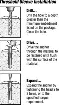
C. 2 ton Scissor Jack – expands & creates a secure t within door frame
D. Neoprene Sleeve- surrounds entire system & provides a watertight seal around its perimeter
MAIN JACK POINT (HORIZONTAL MOVEMENT OF BARRIER)
SECURITY PIN
(NO ADJUSTMENT)
4 X ADJUSTING BOLTS
(TO CREATE DOWNWARD PRESSURE/SEAL)
A. D.B.
C.
Back shown without
Neoprene Sleeve
Back shown with
Neoprene Sleeve
Front shown with
Neoprene Sleeve

3
Flood Gate Manual | www.quickdams.com
BOX COMPONENTS
FLOOD GATE SIZES
DOORWAY ANATOMY
Determine the appropriate size or mixture of sizes of Flood Gates to t your openings.
1. Width of opening (wall to wall within the reveal)
2. Reveal (measured from the outer side of the door frame, or furthest obstruction outwards, to the
corner of the face wall of the building)
3. Construction of Reveal: Make sure that
it is a smooth surface which will create the
most effective seal. If it is not smooth, use
optional Side Rails.
4. Which way does the door/window open
(inwards, outwards, sash, sliding, up and
over, roller shutter).
Flood Gate Neoprene Sleeve
Instructions &
Operations Manual
17mm Ratchet Wrench
Box components:
Box components:
Box components:
Flood Gate Size 25in- 30in
Max. Expansion: 34in
Height: 26.5in
Flood Gate Size 30in- 35in
Max. Expansion: 39in
Height: 26.5in
Flood Gate Size 35in - 40in
Max. Expansion: 44in
Height: 26.5in
Flood Gate Size 40in - 45in
Max. Expansion: 49in
Height: 26.5in
Flood Gate Size 45in - 50in
Max. Expansion: 54in
Height: 26.5in
Note:
For openings wider
than 50in, stanchions
must be used.
See Flood Gate
Stanchion Installation
& Maintenance
section of this
manual on page 10.
DOOR
Example:
Inside of building
Reveal
Door-frame
Width of Opening
Outer wall
A A
D
A
For optimum layout, the Flood Gate can expand approximately
9in, but staying closer to 5in is preferred. Follow the guide
to right to calculate how many units & what size you
may need.
A=Gate Size B width = 0.25in
Stanchion
D width = Opening Size
C width = 0.125in
Side Rails

4
Flood Gate Manual | www.quickdams.com
PLACING THE FLOOD GATE
#1 Inward Opening Door (Preferred Placement):
#2 Outward Opening Door:
#3 Other Openings:
Ideally, the Flood Gate should be placed on the outside of the property, in the reveal. All buildings differ in
the amount of reveal available and their surface type; it is recommended that you check your wall and oor
surfaces to ensure that water cannot seep under or around the barrier, nor into the side walls or framework.
Add silicone caulk (not included) between Flood Gate and reveal as needed.
Place Flood Gate outside for continued access during ooding.
Place Flood Gate inside for continued access during ooding.
Requires sufcient reveal for the Flood Gate to grip the wall. Ideally, 2” (50 mm) of reveal is recommended,
although 1¼” (32 mm) - 1” (25 mm) may be sufcient as long as the Flood Gate can grip tight. This should be
measured from the furthest outward point on the door (usually the frame but look for threshold at
the bottom of the door that often protrudes into the reveal space).
Note: If door opens out, you will need a minimum distance of 3in between the Flood Gate and
the door to access the jack and bolts with a ratchet socket extension that is a minimum of
27in long (shown at right).
Flood Gates can be used in other entryway situations such as sliding doors, elevator doors, French doors,
garage doors & more!
Inside of building
Door-frame
Outer wall
FLOOD GATE
Example: Preferred Placement. (Outside)
DOOR
DOOR
Inside
Outside
FLOOD GATE PLACEMENT # 1
(PREFERRED)
FLOOD GATE PLACEMENT # 2
Measure this distance for Inward
Opening Door Outside Mount
Measure this distance for Outward
Opening Door Inside Mount
Min. Reveal 1.25”-2” (32 mm - 50 mm)
Min. 3”
Main wall of building
Min. Reveal 1.25”-2” (32 mm - 50 mm)
27in Min.

5
Flood Gate Manual | www.quickdams.com
INSTALLING YOUR FLOOD GATE
By following the procedures in the correct sequence, the barrier
will take approximately 2 minutes to install in position.
STEP ONE
Ensure that your entrance is smooth and clean of dust and debris
at the vertical and base area in preparation for positioning.
WARNING - Rough surfaces may damage the sleeve & leave area
for possible seepage.
STEP TWO
Place the barrier with its face (see Diagram 1) toward the ood
threat and as close as possible to your entrance in a solid reveal.
WARNING - If you are not sure the reveal can withstand the forces that
will be applied to it you MUST seek advice from a structural engineer.
STEP THREE
Keeping the unit in an upright position, apply downward pressure
to the unit, while adjusting the horizontal scissor jack -
(see Diagram 2).
WARNING - Over extending the unit may weaken it and reduce its
effectiveness. It is recommended that expansion be no more than
5inches(12.7cm).Ifalargerunitwouldttheopening,itmustbe
used instead of over extending a smaller unit.
STEP FOUR
Hand tighten each of the 4 downward pressure bolts to a
maximum depth of ¼” (7 mm) to compact the sleeve along the
ground - (see Diagram 3).
WARNING - DO NOT fully tighten these bolts as this will cause the
Flood Gate to rise off the surface & cause seepage. Only tighten
enough to gently compress neoprene sleeve.
STEP FIVE
Silicone caulk may be used (see Diagram 4), in accordance with
the manufacturer’s instructions, on the exterior edges of the frame
to ensure a complete seal. The use of added neoprene strips may
be used to increase the water tight seal.
Optional for rough
finish edges
Diagram C
Diagram B
WALL
Optional for rough
finish edges
Diagram C
Diagram B
WALL
Optional for rough
finish edges
Diagram C
Diagram B
WALL
Optional for rough
finish edges
Diagram C
Diagram B
WALL
Diagram 1
Diagram 2
Diagram 3
Diagram 4
Diagram A
Diagram A1
Diagram A
Diagram A1
Diagram A
Diagram A1
Diagram A
Diagram A1
Diagram A
Diagram A1
Hand tighten bolts

6
Flood Gate Manual | www.quickdams.com
Side Rails
(optional)
Side Rails
(optional)
Flood Gate
Apply silicone caulk on outside joints and
along bottom of the new frame.
Side Rail for front and
back pressure support
Added frame
(not included)
Side Rails
(optional)
Side Rails
(optional)
Flood Gate
Apply silicone caulk on outside joints and
along bottom of the new frame.
Side Rail for front and
back pressure support
Added frame
(not included)
Side Rails
(optional)
Side Rails
(optional)
Flood Gate
Apply silicone caulk on outside joints and
along bottom of the new frame.
Side Rail for front and
back pressure support
Added frame
(not included)
SIDE RAILS
Side Rails are designed to add extra support as well as a smooth wall for a better seal.
#1 Doorways With No Reveal
#2 No Door Frame Options
#3 Openings too wide for Flood Gates:
Many doors, particularly PVC doors, patio doors and French windows, are tted almost ush with the outer
face of the building. In these situations, you would need to consider how you can sufciently extend the
reveal to allow the barrier to work
Use a pair of Side Rails (optional) to t to either the reveal or the outer face of the building and provide a
solid point to which the Flood Gates can t into. (See Example 1.)
Example 1: Side Rails (optional accessory)
To t the Flood Gate in a wall where the side walls are not adequate, you will need to create a side wall
support of some kind, using optional Side Rails as shown in example below.
If opening is greater than 50in, an additional frame may be added to decrease opening size. However,
please ensure that the screw heads do not protrude from the frame and stanchions may be used to connect
multiple units together.
Note:WhereSideRailsarettedtothewall,thesidesshouldbesealedwithcaulkbetweenthe
side wall & the Side Rail itself to ensure water cannot bypass between the wall & Flood Gate.
Always ensure the joints between
the new frame and the existing wall/
frame are ‘sealed’ with a water
resistant silicone caulk to protect
against water intrusion.
Note:IfyoudoNOThaveastandarddoorthattstheFloodGate,pleasereviewthe
following options to adapt your door frame to accommodate the Flood Gate

7
Flood Gate Manual | www.quickdams.com
C
BA
INSTRUCTIONS FOR STANCHION & SIDE RAILS
To connect multiple Flood Gates together the Stanchion set must be used
The parts shown in illustration (A) come in one kit with all of the necessary hardware. Illustration (B) shows
the Side Rails that are sold in pairs.
The condition of your existing surface and installation options should be discussed with a qualied architect,
engineer or contractor. General knowledge in concrete construction is necessary for this project.
It is important that the Side Rails and Stanchions are square to the ground surface and parallel
to each other.
TOP
BOTTOM
Flood water
comes from
this side
Ground
UNDERGROUND
Upright Stanchion
Base
TOP
BOTTOM
Flood water
comes from
this side
Ground
UNDERGROUND
Upright Stanchion
Base
TOP
BOTTOM
Flood water
comes from
this side
Ground
UNDERGROUND
Upright Stanchion
Base
A: Upright Stanchion B: Side Rails

8
Flood Gate Manual | www.quickdams.com
SIDE RAILS: PREPARING THE OPENING
Ensure the planning and evaluation stage is complete. Identify the products you require and carry out any
remedial work that is necessary to square and even wall reveals and ground area. If your frame is not secure
or is uneven, then installing side rails (optional) may be necessary.
Installing the Side Rails
Ensure the right and left jamb edges are square with the oor at least 30 inches (76 cm) high.
(See illustration E and illustration F). When the corners are squared, you can install the Side Rails.
(See illustration G and illustration H).
IMPORTANT: Before you drill and install the Side Rail screws, you must apply a generous coat
of silicone caulk to the full length of each surface of the Side Rail where it comes in contact
with the backing surfaces (e.g. reveal, doorstop, jamb plate, brick molding).
Illustration H: Screw selection will depend on the mounting surface*. For wood, use #10 x 1-1/4in
woodscrewssuitableforoutdooruse.Formasonry,3/16inatheadscrewsshouldbeused.Besure
to apply silicone to all surfaces that will be screwed to the structure
Note the design of the Side Rails: There is a larger access hole for the drill bit. The cap
on top of the side rail prevents the Flood Gate from riding up when tightening the
tension bolts on the lower edge of the Flood Gate, reducing the amount of horizontal
pressure required to secure the Flood Gate in place.
If you are fastening against a masonry surface, use a carbide tipped drill bit. Use screws suitable for
wood and concrete. If threading into wood, you need to drill a pilot hole rst.
90º 90º
FRONT VIEW
90º
30”
TOP VIEW
DOOR STOP
JAMB PLATE
SIDE RAILS
(OPTIONAL EXTRA)
THE 2 SIDE RAILS
MUST BE IN ALIGNMENT
RIGHT SIDE DOOR FRAME TOP VIEW
DOOR
1 1/4”
BRICK
MOLDING
SIDE RAILS
(OPTIONAL EXTRA)
DOOR JAMB
DOOR STOP
APPLY SILICONE THE
FULL LENGTH OF
BOTH FACES
90º 90º
FRONT VIEW
90º
30”
TOP VIEW
DOOR STOP
JAMB PLATE
SIDE RAILS
(OPTIONAL EXTRA)
THE 2 SIDE RAILS
MUST BE IN ALIGNMENT
RIGHT SIDE DOOR FRAME TOP VIEW
DOOR
1 1/4”
BRICK
MOLDING
SIDE RAILS
(OPTIONAL EXTRA)
DOOR JAMB
DOOR STOP
APPLY SILICONE THE
FULL LENGTH OF
BOTH FACES
90º 90º
FRONT VIEW
90º
30”
TOP VIEW
DOOR STOP
JAMB PLATE
SIDE RAILS
(OPTIONAL EXTRA)
THE 2 SIDE RAILS
MUST BE IN ALIGNMENT
RIGHT SIDE DOOR FRAME TOP VIEW
DOOR
1 1/4”
BRICK
MOLDING
SIDE RAILS
(OPTIONAL EXTRA)
DOOR JAMB
DOOR STOP
APPLY SILICONE THE
FULL LENGTH OF
BOTH FACES
90º 90º
FRONT VIEW
90º
30”
TOP VIEW
DOOR STOP
JAMB PLATE
SIDE RAILS
(OPTIONAL EXTRA)
THE 2 SIDE RAILS
MUST BE IN ALIGNMENT
RIGHT SIDE DOOR FRAME TOP VIEW
DOOR
1 1/4”
BRICK
MOLDING
SIDE RAILS
(OPTIONAL EXTRA)
DOOR JAMB
DOOR STOP
APPLY SILICONE THE
FULL LENGTH OF
BOTH FACES
L
o
r
em
ip
s
u
m
d
o
lo
r
WELDED CAP
GOES ON TOP
E F
H
G
*Consult with contractor for recommendations on correct hardware for cement or stone surfaces

9
Flood Gate Manual | www.quickdams.com
Method used to repel water
(Recommended)
It may be necessary to make ller pieces to
make rails square to mounting surface.
The faces of the structure adjacent to where the rails will be mounted must be parallel and in line
with each other.
Correct:
Incorrect:
(Not Straight)
90°
Add Filler
Piece
A A
B B
C C
D D
4
4
3
3
2
2
1
1
DO NOT SCALE DRAWING
Angle filler
SHEET 1 OF 1
UNLESS OTHERWISE SPECIFIED:
SCALE: 1:24
WEIGHT:
REV
DWG. NO.
C
SIZE
TITLE:
NAME
DATE
COMMENTS:
Q.A.
MFG APPR.
ENG APPR.
CHECKED
DRAWN
FINISH
MATERIAL
INTERPRET GEOMETRIC
TOLERANCING PER:
DIMENSIONS ARE IN INCHES
TOLERANCES:
FRACTIONAL
ANGULAR: MACH
BEND
TWO PLACE DECIMAL
THREE PLACE DECIMAL
APPLICATION
USED ON
NEXT ASSY
PROPRIETARY AND CONFIDENTIAL
THE INFORMATION CONTAINED IN THIS
DRAWING IS THE SOLE PROPERTY OF
<INSERT COMPANY NAME HERE>. ANY
REPRODUCTION IN PART OR AS A WHOLE
WITHOUT THE WRITTEN PERMISSION OF
<INSERT COMPANY NAME HERE> IS
PROHIBITED.
Straight Edge
A A
B B
C C
D D
4
4
3
3
2
2
1
1
DO NOT SCALE DRAWING
correct
SHEET 1 OF 1
UNLESS OTHERWISE SPECIFIED:
SCALE: 1:24
WEIGHT:
REV
DWG. NO.
C
SIZE
TITLE:
NAME
DATE
COMMENTS:
Q.A.
MFG APPR.
ENG APPR.
CHECKED
DRAWN
FINISH
MATERIAL
INTERPRET GEOMETRIC
TOLERANCING PER:
DIMENSIONS ARE IN INCHES
TOLERANCES:
FRACTIONAL
ANGULAR: MACH
BEND
TWO PLACE DECIMAL
THREE PLACE DECIMAL
APPLICATION
USED ON
NEXT ASSY
PROPRIETARY AND CONFIDENTIAL
THE INFORMATION CONTAINED IN THIS
DRAWING IS THE SOLE PROPERTY OF
<INSERT COMPANY NAME HERE>. ANY
REPRODUCTION IN PART OR AS A WHOLE
WITHOUT THE WRITTEN PERMISSION OF
<INSERT COMPANY NAME HERE> IS
PROHIBITED.
A A
B B
C C
D D
4
4
3
3
2
2
1
1
DO NOT SCALE DRAWING
incorrect
SHEET 1 OF 1
UNLESS OTHERWISE SPECIFIED:
SCALE: 1:24
WEIGHT:
REV
DWG. NO.
C
SIZE
TITLE:
NAME
DATE
COMMENTS:
Q.A.
MFG APPR.
ENG APPR.
CHECKED
DRAWN
FINISH
MATERIAL
INTERPRET GEOMETRIC
TOLERANCING PER:
DIMENSIONS ARE IN INCHES
TOLERANCES:
FRACTIONAL
ANGULAR: MACH
BEND
TWO PLACE DECIMAL
THREE PLACE DECIMAL
APPLICATION
USED ON
NEXT ASSY
PROPRIETARY AND CONFIDENTIAL
THE INFORMATION CONTAINED IN THIS
DRAWING IS THE SOLE PROPERTY OF
<INSERT COMPANY NAME HERE>. ANY
REPRODUCTION IN PART OR AS A WHOLE
WITHOUT THE WRITTEN PERMISSION OF
<INSERT COMPANY NAME HERE> IS
PROHIBITED.
Be sure screws are ush with the inside surface of the rail leakage. Failure to do so could result in damage
to the neoprene sleeve.
A A
B B
C C
D D
4
4
3
3
2
2
1
1
DO NOT SCALE DRAWING
flush
SHEET 1 OF 1
UNLESS OTHERWISE SPECIFIED:
SCALE: 1:4
WEIGHT:
REV
DWG. NO.
C
SIZE
TITLE:
NAME
DATE
COMMENTS:
Q.A.
MFG APPR.
ENG APPR.
CHECKED
DRAWN
FINISH
MATERIAL
INTERPRET GEOMETRIC
TOLERANCING PER:
DIMENSIONS ARE IN INCHES
TOLERANCES:
FRACTIONAL
ANGULAR: MACH
BEND
TWO PLACE DECIMAL
THREE PLACE DECIMAL
APPLICATION
USED ON
NEXT ASSY
PROPRIETARY AND CONFIDENTIAL
THE INFORMATION CONTAINED IN THIS
DRAWING IS THE SOLE PROPERTY OF
<INSERT COMPANY NAME HERE>. ANY
REPRODUCTION IN PART OR AS A WHOLE
WITHOUT THE WRITTEN PERMISSION OF
<INSERT COMPANY NAME HERE> IS
PROHIBITED.
Incorrect:
Not Flush
Correct:
Flush

10
Flood Gate Manual | www.quickdams.com
STANCHIONS: LAYING OUT THE HOLE LOCATION
STANCHIONS: LAYING OUT THE HOLE LOCATION
An engineer will advise on the most appropriate method of boring the hole. Two popular methods include
(but are not limited to) the use of a high pressure water saw or a diamond faced concrete hole drill.
Use a straight, rigid guide bar (not supplied), cut to the width of the door opening. A guide bar made of
1 ¼” x 1 ¼” x 1/8” (31.75 mm x 31.75 mm x 3.17 mm) angle steel or aluminum is recommended.
Mark a line across the guide bar at appropriate intervals (See illustration I in red). These marks represent the
centerline spacing of the holes to be bored. The intervals depend on the mix of Flood Gate units you
identied at the planning stage as the most suitable.
Lay a carpenter’s square on the oor against the inner surface of the guide bar and mark a vertical line. Then
measure 3in from the guide bar & mark a horizontal line. These lines become the center of each bored hole.
This illustration is an Example of an opening of 200in for (A). Using 5 Flood Gates, each stanchion,
or dimension (B) is positioned at their respective center lines.
CAUTION: Whether or not you opt to use the Side Rails, the 3 in. / 76.2 mm centerline dimension of the
bored Stanchion holes must always be maintained from whatever surface the back face of the Flood Gate
comes into contact with on the opening.
NOTE: The 3in/76.2mm set back dimension to the center line of the bored holes
is critical to ensure proper alignment of the Flood Gate panels.
J
I
J
BORING THE HOLES FOR THE BASE
40” (B)40” (B) 40” (B)40” (B) 40” (B)
3”
3”
8”
200” (A)
This illustration is an Example of an opening of 14¼ ft for (A). Using 5 Flood Gates, each stanchion, or
dimension (B) is positioned at their respective center lines.
NOTE: The 3 in. / 76.2 mm set back dimension to the center line of the bored holes is
critical to insure proper alignment of the Flood Gate panels.
ILL J
BORING THE HOLES FOR THE BASE
ILL I
90º
SHIMS OR CLAMPS
ON BOTH ENDS
AS SHOWN
STRAIGHT RIGID
STEEL GUIDE BAR
LINE MARKED
ACROSS BAR
3”
CENTER LINE OF
STANCHION
Whether or not you opt to use the side rails, the 3 in. / 76.2 mm centerline dimension
of the bored stanchion holes must always be maintained from whatever surface the back
face of the Flood Gate comes into contact with on the opening.
CAUTION:
BORING THE HOLES FOR THE BASE
40” (B)40” (B) 40” (B)40” (B) 40” (B)
3”
3”
8”
200” (A)
This illustration is an Example of an opening of 14¼ ft for (A). Using 5 Flood Gates, each stanchion, or
dimension (B) is positioned at their respective center lines.
NOTE: The 3 in. / 76.2 mm set back dimension to the center line of the bored holes is
critical to insure proper alignment of the Flood Gate panels.
ILL J
BORING THE HOLES FOR THE BASE
ILL I
90º
SHIMS OR CLAMPS
ON BOTH ENDS
AS SHOWN
STRAIGHT RIGID
STEEL GUIDE BAR
LINE MARKED
ACROSS BAR
3”
CENTER LINE OF
STANCHION
Whether or not you opt to use the side rails, the 3 in. / 76.2 mm centerline dimension
of the bored stanchion holes must always be maintained from whatever surface the back
face of the Flood Gate comes into contact with on the opening.
CAUTION:
This example uses 35in Flood Gates that expand to 40in.

11
Flood Gate Manual | www.quickdams.com
Once the brackets are assembled to the Base, measure and mark the centerline on
each angle bracket. These lines will be used to position the Base in the bored hole
PREPARING THE GROUND SURFACE AND BASE RECESS
Concreteoorsandslabsvarygreatlyintermsofthicknessandtype
of concrete. You must create a recess beneath the surface for the
anchor which is then set in the concrete foundation. With this style
ofconstructiontheriskassociatedwithundersizeoorthickness,
cracks and inadequate concrete reinforcement is greatly reduced.
The two angles are the same, but the Front Angle
Bracket is the one which is the positioning gauge for
each Stanchion, therefore it must be squared with the side
edge of the Base prior to tightening. (See illustration K).
The Rear Angle Bracket need not be squared.
Top View: Face (A) and (B) must be
square to each other as shown. A simple
6 in. square works nicely for this.
Side View
90º
A
B
FRONT
ANGLE
BRACKET
REAR
ANGLE
BRACKET
8”
10”
EXISTING
CONCRETE
SLAB
EXISTING
CONCRETE
SLAB
SUB
SOIL
SUB
SOIL
EXISTING
CONCRETE
SLAB
POSITIONING GAUGE
ANGLE FRONT
SUPPORT RIB
FACES TOWARDS
OUTSIDE OF
BUILDING
CENTER LINE OF ANCHOR
SHOULD BE ON CENTER
LINE OF HOLE AS SHOWN
OUTSIDE OF BUILDING
ANCHOR
ASSEMBLY
ANCHOR
ASSEMBLY
TOWARDS
FLOOD
WATER
A A
B B
C C
D D
4
4
3
3
2
2
1
1
DO NOT SCALE DRAWING
square
SHEET 1 OF 1
UNLESS OTHERWISE SPECIFIED:
SCALE: 1:4
WEIGHT:
REV
DWG. NO.
C
SIZE
TITLE:
NAME
DATE
COMMENTS:
Q.A.
MFG APPR.
ENG APPR.
CHECKED
DRAWN
FINISH
MATERIAL
INTERPRET GEOMETRIC
TOLERANCING PER:
DIMENSIONS ARE IN INCHES
TOLERANCES:
FRACTIONAL
ANGULAR: MACH
BEND
TWO PLACE DECIMAL
THREE PLACE DECIMAL
APPLICATION
USED ON
NEXT ASSY
PROPRIETARY AND CONFIDENTIAL
THE INFORMATION CONTAINED IN THIS
DRAWING IS THE SOLE PROPERTY OF
<INSERT COMPANY NAME HERE>. ANY
REPRODUCTION IN PART OR AS A WHOLE
WITHOUT THE WRITTEN PERMISSION OF
<INSERT COMPANY NAME HERE> IS
PROHIBITED.
A
B
90º
A
B
FRONT
ANGLE
BRACKET
REAR
ANGLE
BRACKET
8”
10”
EXISTING
CONCRETE
SLAB
EXISTING
CONCRETE
SLAB
SUB
SOIL
SUB
SOIL
EXISTING
CONCRETE
SLAB
POSITIONING GAUGE
ANGLE FRONT
SUPPORT RIB
FACES TOWARDS
OUTSIDE OF
BUILDING
CENTER LINE OF ANCHOR
SHOULD BE ON CENTER
LINE OF HOLE AS SHOWN
OUTSIDE OF BUILDING
ANCHOR
ASSEMBLY
ANCHOR
ASSEMBLY
TOWARDS
FLOOD
WATER
K
M
N
L
TOP
BOTTOM
Flood water
comes from
this side
Ground
UNDERGROUND
Upright Stanchion
Base
ASSEMBLING THE ANGLE BRACKETS TO THE BASE
When the holes are bored and cleaned you are ready to set up the Base.
1. Assemble the two angle brackets to the Base using the four allen head cap screws.
Finger tighten at this point. (See illustration K)
NOTE: The angle brackets are used to support the Base in position while cement cures. Once cured-
they will be removed & discarded. (See illustration N).
2. Using a small square adjust the front angle bracket so it’s square to the top side edge
of the Base. (see illustration K, L and N).
3. While holding the front angle bracket square to the Base, tighten all four cap screws.
4. Re-check the front angle bracket again with the square (see illustration L).
5. Firmly clamp or block shim each end of the rigid straight edge into the Side Rails and against
the oor. Ensure that the centerline marks (which are put on to the straight edge earlier - see
illustration I) are facing upward as these are the marks which you must later line up with the centerline
marks scribed on to the face of the angle brackets (see illustration M).

12
Flood Gate Manual | www.quickdams.com
INSERTING BASE ASSEMBLIES
Pour and ll the hole with concrete to a depth of 4 inches from the top and tap or vibrate the concrete to
ensure it completely settles at the bottom of the hole. Position the Base down into the concrete.
1. Align the center line marks on the angle brackets with the line marks on the center edge. (See illustration P).
Ensureyouclampthecenterlinemarkstogethersothatbothanglebracketsarerestingatonthesurfaceoftheoor.
(See illustration N).
NOTE: Each Base is designed with a 3” x 3” hollow square tube. At the very top of the tube and
through its rear wall, just under the threaded plate, there is a 3/4” hole in the tube. This hole allows air to
escape from the inside of the tube while the inside is lling with concrete. (See illustration O)
2. While lling with concrete, gently tap on the very
center of the top of the Base with a block of wood
or handle end of a hammer.
ItiscriticalthattheinsideoftheBaseiscompletelylledwith
concrete to maintain maximum strength.
3. Ensure the top edge of angle brackets are ush with the
surface of the ground.
Do not remove the clamps and angle brackets for at least 24 to 36
hours depending on the temperature, humidity and soil mechanics to
allow concrete to set.
AIR
RELIEF
HOLE
RIDGED
STRAIGHT
EDGE
CLAMP (4)
(not included)
Center line mark on
face of Angle Bracket
must line up with
marks on Ridged
Straight Edge
Center line mark on
Face of front angle
Bracket
Dimension B
from ILL J
Straight Edge
C-Clamps
Align center mark with
line on the straight edge
A A
B B
C C
D D
4
4
3
3
2
2
1
1
DO NOT SCALE DRAWING
boring the holes
SHEET 1 OF 1
UNLESS OTHERWISE SPECIFIED:
SCALE: 1:24
WEIGHT:
REV
DWG. NO.
C
SIZE
TITLE:
NAME
DATE
COMMENTS:
Q.A.
MFG APPR.
ENG APPR.
CHECKED
DRAWN
FINISH
MATERIAL
INTERPRET GEOMETRIC
TOLERANCING PER:
DIMENSIONS ARE IN INCHES
TOLERANCES:
FRACTIONAL
ANGULAR: MACH
BEND
TWO PLACE DECIMAL
THREE PLACE DECIMAL
APPLICATION
USED ON
NEXT ASSY
PROPRIETARY AND CONFIDENTIAL
THE INFORMATION CONTAINED IN THIS
DRAWING IS THE SOLE PROPERTY OF
<INSERT COMPANY NAME HERE>. ANY
REPRODUCTION IN PART OR AS A WHOLE
WITHOUT THE WRITTEN PERMISSION OF
<INSERT COMPANY NAME HERE> IS
PROHIBITED.
P
O
Straight Edge
C-Clamps
Align center mark with
line on the straight edge
A A
B B
C C
D D
4
4
3
3
2
2
1
1
DO NOT SCALE DRAWING
boring the holes
SHEET 1 OF 1
UNLESS OTHERWISE SPECIFIED:
SCALE: 1:24
WEIGHT:
REV
DWG. NO.
C
SIZE
TITLE:
NAME
DATE
COMMENTS:
Q.A.
MFG APPR.
ENG APPR.
CHECKED
DRAWN
FINISH
MATERIAL
INTERPRET GEOMETRIC
TOLERANCING PER:
DIMENSIONS ARE IN INCHES
TOLERANCES:
FRACTIONAL
ANGULAR: MACH
BEND
TWO PLACE DECIMAL
THREE PLACE DECIMAL
APPLICATION
USED ON
NEXT ASSY
PROPRIETARY AND CONFIDENTIAL
THE INFORMATION CONTAINED IN THIS
DRAWING IS THE SOLE PROPERTY OF
<INSERT COMPANY NAME HERE>. ANY
REPRODUCTION IN PART OR AS A WHOLE
WITHOUT THE WRITTEN PERMISSION OF
<INSERT COMPANY NAME HERE> IS
PROHIBITED.

13
Flood Gate Manual | www.quickdams.com
GENERAL MAINTENANCE AND INSTALLATION
Removing the clamp
Keep the allen screws and allen wrench in a safe place as they will
be needed to secure the Stanchion to the Base in the event of
a ood.
Maintaining the Base
1. There are (4) 1/2 in. - grub screws with every Stanchion.
These must be coated with a waterproof grease or anti-seize
compound and screwed into the holes on each plate. This will
protect the threads in the plate and allow trafc to move
across the anchor plate without damaging the threads
(See illustration Q).
2. These plugs should be ush with the top of the Base and no
deeper. They should also be re-greased periodically and after
every use to ensure they will come out when needed.
Before Installing the Stanchion
IMPORTANT: To prevent any leaking between the top of the Base and the bottom of the
Stanchionthereisamachined3/16”groovewhichshouldbelledwithsiliconecaulkto
add additional sealing (See illustration R).
Maintaining the sealing surfaces
Always keep the top of the Base and the bottom of the Stanchion clean and free of nicks and dents
as these are critical sealing surfaces.
SEALING
GROOVE
SEALING
GROOVE
Q
R

14
Flood Gate Manual | www.quickdams.com
AFTER-USE
Flood Gate Maintenance Instructions
1. Return the horizontal and vertical operating mechanisms to their closed position.
2. Remove the unit from its position.
3. Remove the sleeve and examine for damage caused by stress, use or wear and tear.
Repair or replace as necessary.
4. The sleeve can be hand washed in warm water up to 104° F (40° C). Rinse in cold water and hang
to dry in shaded area. DO NOT TUMBLE DRY.
5. Dry off excess moisture from the metal frame. Examine for damage caused by stress, use or wear and
tear. Apply rust proong oil or grease to all expandable mechanisms.
6. Once all parts of the unit are dry, the unit can be stored for future use.
Storing your Flood Gate
1. Store the unit in a secure location and only allow access by a responsible adult.
2. The unit should be stored in its closed and upright position. DO NOT STORE IN AN EXPANDED STATE.
3. Store the unit and its accessories in a dry and well ventilated area. DO NOT STORE IN
DIRECT SUNLIGHT.
4. DO NOT EXPOSE THE PRODUCT TO EXTREME TEMPERATURES AND KEEP AWAY FROM
OPEN FLAMES.
5. Place the unit in storage in it’s normal upright position, keeping the sleeve separate & at to
maintain it’s shape.
6. If you are storing more than one unit and do not intend on using the original packaging, the gates must
be stored face to face (The face as shown in Diagram A).
7. DO NOT STORE FACE TO BACK OR BACK TO BACK AS THIS CAN DAMAGE THE PRODUCTS.
8. Review the unit and its mechanisms periodically to ensure that the conditions of storage have not
reduced its effectiveness.
TERMS & CONDITIONS
Flood Gate is intended to be used as outlined in this document and other Absorbent Specialty Products (ASP) literature. Data and
information provided in this document is for general information purposes only. Conditions for each use of the Flood Gate will vary
and are beyond the control of ASP. ASP cannot guarantee desired results. When purchasing this product from ASP, you agree to as-
sume all risks that may arise from ownership, installation, and use of the Flood Gate and agree to release ASP from any and all claims
brought by any person or entity against ASP related to and/or arising from your ownership, installation, and/or use of the Flood Gate.
ASP shall not be liable for any improper or incorrect ownership, installation or use of this product and assumes no responsibility for
anyone’s ownership, installation or use of this product. In no event shall ASP be liable for any direct, indirect, incidental, special, ex-
emplary or consequential damages (including, but not limited to: procurement or substitute goods or services; loss of use or prots;
or business interruption) however caused and on any theory arising in any way out of the use of this product, even if advised of the
possibility of such damage. This disclaimer of liability applies to any damages, injury or death, whether based on alleged breach of
contract, tortuous behavior, negligence or any other cause of action, including and not limited to damages or injuries caused by any
failure of performance, error, omission, defect or delay in operation.
LIMITED WARRANTY
ASP warrants this product and components to be free from defects in material and workmanship for a period of one (1) year from
date of shipment. If within the term of this warranty, if any Flood Gate component is found to be defective upon inspection by an
authorized Flood Gate representative, ASP will replace or repair, at ASP’s discretion, any part found to be defective. Unauthorized
modication of this product voids this limited warranty. The neoprene sleeve is considered a “wear-item” and is not covered under
this warranty. Replacements can be purchased from ASP. Moving parts must be properly maintained prior to storage.
To make a claim under this warranty, contact ASP at this address:
Absorbent Specialty Products | 1 John C. Dean Memorial Blvd. | Cumberland, RI 02864 | 888-761-4405 | [email protected]

THE NEXT GENERATION IN FLOOD PROTECTION
TM
PROTECTING
THESE INDUSTRIES
UniversitiesConstructionGovernment Grocery ResidentialHospitals HotelsJanitorialProperty
Management
Retail
Visit us at www.quickdams.com or call 888-761-4405
Be Prepared &
Be Protected
QD_Flood_Gate_manual
& MORE
© 2019 Quick Dam, Flood Gate & Absorbent Specialty Products. All rights reserved. No part of
this manual may be reproduced, distributed, or transmitted in any form or by any means, without
consent from Quick Dam & Absorbent Specialty Products.
-
 1
1
-
 2
2
-
 3
3
-
 4
4
-
 5
5
-
 6
6
-
 7
7
-
 8
8
-
 9
9
-
 10
10
-
 11
11
-
 12
12
-
 13
13
-
 14
14
-
 15
15
-
 16
16


Ask a question and I''ll find the answer in the document
Finding information in a document is now easier with AI
Related papers
-
Quick Dam QDFG30 User manual
-
-
-
-
-
Quick Dam QDWGWL-2050 Owner's manual
-
-
-
-
Other documents
-
Quiet Glide NT140308 Installation guide
-
 Exit Security Inc SB-01-0036 User guide
-
 EZPole EZL21B Installation guide
-
 Red Head 50123 Installation guide
-
NORTHSTAR 155 RT Quick start guide
-
Friedrich US10D30C Sleeve Installation
-
Unbranded P433FJ Installation guide
-
Gatehouse 918230854N User manual
-
 Mutual Industries 15903-2 Operating instructions
-
 Mr. Chain 99930-4 User manual


