INSTALLATION MANUAL
SM-RAZOR-M/ SM-RAZOR-L
Strong™ Razor In-Wall
Fixed Mount (Black)

NS
WARNINGS:
• Installation by a qualied professional is highly recommended for this product.
• Do not begin installation until you have thoroughly read and understand these instructions.
• Medium mount supports displays from VESA 200X200; 300X300 up to 400X300, and a maximum load of 125 lbs.
Large mount supports displays from VESA 200X200; 300X300 up to 800X500, and a maximum load of 125 lbs.
• Ensure the mounting wall will safely support four times the combined weight of the Mount and display panel.
• The manufacturer does not accept responsibility for incorrect installation.
• Due to low prole, check with the TV manufacturer to ensure the particular display being used can be installed 5mm from the wall.
SPECIFICATIONS:
• Maximum Load: 125 lbs. (56 kg)
• Display Size
Medium: up to VESA 400X300
Large: up to 800X500
BOX CONTENTS:
• Wall Plate (1)
• Arm left (1)
• Arm right (1)
TOOLS REQUIRED:
• Power Drill
• 5/16” and 3/16” Drill Bit
• Phillips Head Screw Driver
• Level
• Drywall Saw
• Stud Finder
PACKAGE CONTENTS:
Wall Plate
Arms
Clear Plastic
Adhesive Sheet (x1)
HARDWARE KIT
(A)1/4” Backplate Spacer (x2)
(P) 25mm×25mm Diameter Washer(x4)
(B) 1/8” Backplate Spacer (x2)
(C) M6x50mm Lag Screws (x4)
(D) Concrete Anchors (x4)
(E) Washers (x4)
(F) 1/4” ABS Spacer (x4)
(G) M4X12 (x4)
(H) M4X25 (x4)
(J) M5X25 (x4)
(L) M6X25 (x4)
(N) M8X25 (x4)
(O) M8X30 (x4)
(K) M6X12 (x4)
(M) M8X12 (x4)
(Q) Allen Key Drill Bit (x1)
(I) M5X12 (x4)
(R) M2.5X55mm Allen Key
(S) M4X100mm Allen Key (T) M5X100mm Allen Key
CAUTION:
These wall mounts are
intended for use only with
the maximum weight of :
SM-RAZOR-M: 125 lbs (56kg)
SM-RAZOR-L: 125 lbs (56kg)
© 2015 STRONG™Page 2

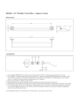
CAUTION:
These wall mounts are
intended for use only with
the maximum weight of :
SM-RAZOR-M: 125 lbs (56kg)
SM-RAZOR-L: 125 lbs (56kg)
Correct
concrete
concrete
plaster/
drywall
plaster/
drywall
Incorrect
Cutaway View
Figure 3
Drill holes and
insert anchors.
Place wall arm
assembly plate
over anchor and
secure with
lag screw.
Tighten all
lag screws.
Wall Arm
Concrete
Wall
Flange Bolt
Figure 4
Figure 1
TIP: If needed,
use a Backplate
Spacer suited for your
drywall thickness when
mounting in the wall
(1/8” for 5/8” drywall,
1/4” for 3/4” drywall).
Figure 2
INSTALLATION:
Note: The SM-RAZOR-M/L mount is designed for in-wall instal-
lations when applicable.
Step 1: Mount the Wall Bracket Assembly
For Mounting into a Stud Wall
a. Use a stud nder to locate stud positioning for optimal
placement. A minimum of two studs are needed.
b. Using the Wall Plate, place against the wall face out
and trace around the outside of the recess. Remove
the Wall Plate and use a dry wall saw to cut and
remove the drywall, leaving studs in place.
c. First verify t of Wall Plate into hole without attaching
(anges should cover cuts), then remove.
d. Optional next step: Remove backing of Clear
Plastic Adhesive Sheet (included) and place over
backside of Wall Plate to cover up exposed holes to
help eliminate draft from in-wall once mount is installed.
e. Pre-drill holes into two wood studs using a 3/16” drill bit.
Be sure to drill into the center of the studs at least
2 ½” deep.
f. If drywall is greater than ½”, determine Spacer
needed (either 1/8” or1/4”) to help set depth of Wall
Plate ush with drywall. Using a drywall screw, install
Spacer (A or B) to stud rst through center, tapered hole.
g. Insert four Lag Screws (C) into holes through the Wall
Plate and tighten down with Allen Key (S).
For Mounting on a Stud Wall
a. Pre-drill holes into two wood studs using a 3/16” drill bit.
Be sure to drill into the center of the studs at least
2-1/2” deep. The use of a stud nder is highly
recommended.
b. Insert four Lag screws (C) into holes through the Wall
Plate and tighten down with Allen Key (S).
WARNING: Tighten bolts so that wall plate is rmly
attached, but do not overtighten. Overtightening
can damage the bolts, greatly reducing their
holding strength.
For Mounting on a Concrete Wall
a. Pre-drill holes into concrete using 5/16” drill bits to a
depth of 2 1/2”. Insert concrete Wall Anchors (D)
and tap in-with hammer, if necessary (Figures 3 & 4).
WARNING: When installing wall arm assembly on
cinder block, verify rst that you have a minimum
of 1-3/8” of concrete thickness to be used for the
concrete anchors. Do not drill into mortar joints! Be
sure to mount in a solid part of the block, generally
1”minimum from the side of the block. Cinder block
must meet ASTM C-90 specications. It is suggested that
a standard electric drill on slow setting is used to drill the
hole instead of a hammer drill to avoid breaking out the
back of the hole when entering a void or cavity.
Concrete must be 2000 psi density minimum.
Lighter density concrete may not hold anchors.
Make sure that the supporting surface will safely
support the combined load of the equipment and
all attached hardware and components.
Page 3

Lifetime Limited Warranty
Strong™ Mounts have a Lifetime Limited Warranty. This warranty includes parts and labor repairs on all components found to be defective
in material or workmanship under normal conditions of use. This warranty shall not apply to products which have been abused, modied or
disassembled. Products to be repaired under this warranty must be returned to SnapAV or a designated service center with prior notication
and an assigned return authorization (RA) number.
For Technical Support call 1.866.838.5052
150326-1650
Lifetime
b. Insert four Lag Screws (C) into the Wall Anchors
through the Wall Plate. Tighten all bolts with
Allen Key (S).
WARNING: Tighten bolts so that wall plate is rmly
attached, but do not overtighten. Overtightening
can damage the bolts, greatly reducing their
holding strength.
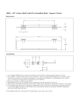
Step 2: Mount Arms to TV
a. Determine the diameter of the screw (parts G through
O) your TV requires by carefully trying to hand-thread
one into the threaded insert on the rear of the TV.
If there is any resistance, stop immediately.
b. Spacers are commonly needed on TVs with
curved backs or recessed screw inserts. The screw
will thread through the appropriate washer (P),
any spacer needed (F) and the arms into the TV.
c. Ensure the arms are installed at side to TV and
are square to each other after all screws have been
installed (Figure 5).
Step 3: Hang TV on to the Wall Plate
a. Carefully lift the TV and place arm hooks over
and onto angled lip in Wall Plate (Figure 7).
Do not release the TV until it is completely connected
to the Wall Plate.
Figure 5
Figure 6
Figure 7
© 2015 STRONG™
/