Page is loading ...

CARF-Models
Valiant
World Class F3A Pattern Airplane
Build and Setup Instructions
for Glow or Electric Power.
A manual of the Valiant’s designer
Bryan Hebert.
Bryan has written the CARF
Valiant Manual while installing a YS 170.
As an additional contribution to this
manual Stuart Chale has written up an
installation manual for an outrunner
electric installation.
We thank Bryan and Stuart for their hard efforts to create this manual
for us and for you!

Page 2
Instruction Manual “Valiant” (Draft Version)
CARF-Models Co., Ltd, Contact email: [email protected]
Dear Customer!
This extensive building and trimming manual was written by nobody less than
Bryan Hebert himself, the designer and prototype builder of the Valiant. Thank
you, Bryan!
We thought that it would be best to invite the designer to explain the construction
details and the building steps. Thus, some of these steps might be very personal
opinion and not always intended by CARF. However, CARF decided to print this
manual without modifications since it has too many good hints and tricks in-
cluded. Please keep in mind that with such a highly professional product there
are many different installations possible and we trust you, as an experienced
modeler and pattern pilot to make your judgement.
For the electric version we thank Stuart Chale for his invaluable contribution.
Here now Bryan’s words:
I want to start out by saying congratulations!
If you’re reading this you must be open to new ideas. I’m going to try to give the best
information I can on the new Comp-Arf models Valiant to help with the building, set up
and trimming of this one-of-a-kind F3A Machine.
Please read this entire manual before you start building and flying the Valiant.
First let me say, airplane setup is very important. The setup will make or break your
performance at any level of competition. With a properly designed and trimmed model,
you will have a distinct advantage over the competition.
The construction, radio and equipment installation is where this begins. The new com-
puter radios can only do a limited amount for you. What we want to do is to set up an
airplane such that the radio is relied upon very little for corrective actions. It should be
used only for molding the radio to the particular "feel " you are looking for with the
model.
I’m going to give you information on how to set this airplane up to fly, with my built-in
settings, in just a few flights. Comp Arf has strived very hard to be as accurate as they
can to give the modeler an airplane that strictly follows my force arrangements. I will
show you how to fly and adjust the model, through a series of maneuvers, for the best
results with very little to NO mix.

Page 3
Instruction Manual “Valiant” (Draft Version)
CARF-Models Co., Ltd, Contact email: [email protected]
First some important information
The weight balance of the Valiant was designed to accommodate most motors with,
some adjustment of the center of gravity (C/G) being needed on others. If you are flying
Glow or Electric, the stabs are cut out for Mini servos, and these servo’s can be in-
stalled in the stab halves, with little adjusting of C/G required to complete final balance
in the radio installation process.
If you intend to use a 2 Stroke, a YS 1.70" NON CDI", or a YS 1.60, the airplane could
be tail heavy, if you install the servo’s in the stabs; so, be careful and thoughtful with
your installation. You may need to run a push rod or pull-pull system on the elevator and
make some cover plates for the stabilizer servo cut outs. This will make it easier to
adjust the proper C/G. Just be aware of the weight during the building process. Shulman
Aviation makes an extension wire for rear servo setup in the stabs that will save you
some weight in the rear of the airframe, should you run the elevator servos in the stabs.
The airplane is supplied with two center tank mounts to mount the tank. It is made to be
used in range from the Tetra™ 16 Ounce to the 20 Ounce and should be installed
centered on the C/G under the wing tube, so there are no trim changes during the
flights. If you are running a standard YS1.60 or 1.70, I would recommend a 16 to 20
ounce tank. If you choose to run a YS ignition motor, you can get by with only a 12-
ounce tank for any pattern in use today. However, the tank cutouts are standard for the
20 Ounce Tetra Crank Tank, and they will need to be modified if you use a smaller tank.
The C/G is on the center of the wing tube, so place the tank in this position for best
results.
Engine cooling
This is a big issue for YS Motors, especially the 1.70 YS.
You may have to dam your engine compartment with foam around the engine head to
ensure proper airflow around the engine head. YS engine box foam works great for this
purpose. Look at the photos in this manual. If using a YS 1.70, you will need to remove
the center of the cut out in the front of the chin, for the best cooling on the hottest days.
Also, you may choose not to add the side cut out like I recommend on the chin. If you
choose not to use this cooling method, make sure you cut a big enough cooling exit for
good airflow.
Very Important Information on the center hinge wings and stabs
Comp Arf has manufactured a very nice and precise product, however, some precau-
tions are required by you, the builder. You must install very precise, quality servos in the
wings. If there is excessive looseness around center, along with engine vibration, you
may encounter aileron flutter, so chose your servos carefully. Do not disregard this step.
The same pertains to the elevators; you must use very precise servos for best results

Page 4
Instruction Manual “Valiant” (Draft Version)
CARF-Models Co., Ltd, Contact email: [email protected]
Motor mounts
I recommend the LR 85 Hyde mount for this airplane. I worked with Merle Hyde on the
application and operation of this mount, having tested all of his mounts on this airframe,
and finding the LR 85 to be the best overall for my composite designs. The motor mount
is important because of the center hinging of control surfaces. The better the mount the
longer the hinges stay tight and free of slack.
Servo’s and Linkage
I recommend, for best results, using Futaba™ BLS Brushless servos, or an equivalent.
For elevator halves, use the BLS 651, for ailerons use the BLS 551. On rudder, use a
200-inch ounce servo for the most consistent results.
For clevises on the glow models, I recommend the Tetra™, Central Hobbies™ or MK ™
BB clevises where possible, for all surfaces and Central Hobbies™ Carbon/Titanium
push rod systems. It is important to have as little linkage slack or looseness as possible,
for the best trimming, flying and durable results. Remember, quality servos produce
quality results!
Now lets get to the building
These instructions are specific to a glow engine setup. Some of the building will be
applicable to electric versions, but this manual is specific to the glow setup. The electric
version can be built with a slightly lighter process.
I have replaced the aileron, and rudder clevis arms with a sunken dowel to give the
ability to use Tetra BB linkages. This will give the best results for longevity and slack
free usage. If you choose to use the rudder arm supplied in the kit, make sure it is
installed far enough back so that it does not hit the fin during extreme rudder throws.
For the elevator, in this example, we use the supplied arms. I feel this is the best setup.

Page 5
Instruction Manual “Valiant” (Draft Version)
CARF-Models Co., Ltd, Contact email: [email protected]
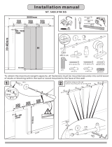
First we will start on the motor Mount/
fire wall installation
#1 Cut out a 82mm diameter disk 1 to
1.5 mm thick to make a spacer for
hanging the engine from the nose ring.
Hold the fuselage vertical.
Insert the engine in the fuse, and install
the spacer disk /spinner on the engine
and hang it centered on the nose of the
airframe.
#2 From the rear, insert the motor
mount up to the motor and screw it to
the motor
#3 Slide the firewall to the motor mount,
making sure the alignment of the engine
is still true. Realign if required and then
tack glue the firewall to the fuse with
cyanoacrylate glue (C/A), so it can be
handled a little without becoming dis-
lodged easily.
#4 VERY IMPORTANT, turn the engine
off centered, looking at the nose, 6mm
to the left and tack glue the motor mount
to the firewall. This will give a little extra
room for engine backfires
#5 Remove the motor, but leave the
motor mount tack glued to the firewall.
#6 Mix some 2-hour epoxy, along with
carbon/graphite powder for a thickening
agent. Dam the front side of the motor
mount with tape so the epoxy won’t seep
through. Turn the fuse on its nose and,

Page 6
Instruction Manual “Valiant” (Draft Version)
CARF-Models Co., Ltd, Contact email: [email protected]
using an applicator or a brush, apply the
glue to the firewall.
When the firewall glue is completely
hardened, drill the holes in the motor
mount through the firewall and install the
blind nuts. Relieve the flashing on the
engine compartment so the motor can-
not touch or rub. See the photos. Drill
the relief hole for the needle valve and
fuel elbow’s to complete the installation.
After the motor is installed, install the
exhaust system. Add a piece of 2mm
plywood across the inside of the fuse
where the mounting for the pipe discon-
nects. Screw in for rigidity and noise
reduction.

Page 7
Instruction Manual “Valiant” (Draft Version)
CARF-Models Co., Ltd, Contact email: [email protected]
Cowling with Quick disconnect
You can use your own method of install-
ing the cowling for the glow version. The
rear pins are already installed at the
factory, with a front screw in place.
However, the front screw will interfere
with the glow engine, so it will have to be
removed and another hold down method
used.
In this example, I will show you how to
make a wood version of the Japanese
cowling quick disconnect. The front
screw is installed for the electric version
but, again, this will interfere with the
engine on a YS. So, it will have to be
removed and the flashing ground away.
Using the supplied instructional photo’s,
build a couple of pin latches for the
disconnect system. Use a spring steel
wire and bend it to the necessary shape.
Relieve the fuse sides near the firewall
to allow the latches to be installed
square to the firewall, and then screw
the setup to the firewall. Using 5mm
aircraft ply, cut out some triangle stand
offs for the pins holders. Using 2.5mm or
6-32 screws, file the heads round so
they can move the spring wire as it is

Page 8
Instruction Manual “Valiant” (Draft Version)
CARF-Models Co., Ltd, Contact email: [email protected]
inserted in the latch. Remember to drill
the holes in the latch equal to the size of
the insert screws.
Cut spacers to insert under the stand-
offs, keeping them vertical to the cowling
on the fuse, and test fit the standoffs to
make sure they touch the cowling sides
(you may have to adjust the wood cowl-
ing alignment inserts installed at the
factory in the middle of the cowling, for
enough slack to be easily installed) After
test fitting, use a thixotropic epoxy glue
mix and glue the standoffs to the cowl-
ing. You will have to cut out cooling exit
holes in the rear of the cowling, see the
supplied photos.

Page 9
Instruction Manual “Valiant” (Draft Version)
CARF-Models Co., Ltd, Contact email: [email protected]
Landing Gear
Assemble the gear using Central Hob-
bies™ aluminum axles, or equivalent, to
keep the weight down. Make sure you
use Loc-tite™ or some other thread lock
compound on the axle screws to pre-
vent the threads from backing off and
losing the wheel and pant in flight.
Relieve the wheel pants wheel area and
test fit a 65mm /2.5 inch wheel, making
sure there is no rubbing on the sides.
Add a piece of 1mm plywood doublers
about 30mm square as a hard point to
mount the axle against, and a hard point
to put an anti-rotation screw to secure
the pants to the gear leg. Measure and
cut a hole in the fuse side directly above
the gear plate for glow (mount it on the
bottom of the fuse in the cowling area if
you are using an electric setup). Cut it
slightly bigger than the gear tongue and
insert the gear one at a time in the fuse.
Measure them square, being careful not
to put in toe-out (both wheels facing out)
because it will be difficult to steer on
take offs, and cause trimming problems
from drag.
Tack glue them to the gear plate when
you’re satisfied with the measurements
on both sides. Drill the gear and the
plate through, and then install the blind
nuts and screws provided in the kit.
Seal the blind nuts with medium thick-
ness CA. You will also need to relieve
the cowling flashing around the gear
blind nut area.
Note: Since with an electric motor you
would use larger props please consider
to mount the gear from below, not from
top. This will require to cut a notch into
each rear corner of the chin cowl to give
room for the gear legs. See the electric
addendum!

Page 10
Instruction Manual “Valiant” (Draft Version)
CARF-Models Co., Ltd, Contact email: [email protected]
Now let start on the Canopy.
#1 Install the supplied hooks a little
beyond the middle of the canopy facing
forward, using a thixotropic epoxy mix.
#2 After this is hardened, measure and
cut receptacle holes for the hooks in the
fuse side canopy flashing. Fit the
canopy, adjust, and glue the phenolic U
receptacle in place as a catch and
alignment socket. They will need to be
trimmed to fit close to the fuse sides.
#3 Use a canopy latch like the BVM™
latch and glue it to the inside of the
canopy with some thixotropic epoxy.
Also, glue a piece of aircraft ply behind
the canopy arch former as a hard point
for the latch pin. While it is hardening,
let’s work on the front.
#4 Cut out a couple of light ply rails and
glue them to the underside of the
canopy flashing on the front of the fuse,
and on top of the canopy flashing on the
canopy, using 15 minute epoxy. Wait for
it to harden. This will help with fuse
noise and rigidity.

Page 11
Instruction Manual “Valiant” (Draft Version)
CARF-Models Co., Ltd, Contact email: [email protected]
#5 After the rear latch is hardened,
install the canopy. Find the rear pin
indent and drill the hole for the rear latch
pin.
#6 Using a Dremel™ barrel grinder, drill
a hole towards the front of the canopy
through the top skin. Then, use a 1/16
drill, after aligning the canopy, and
precisely drill a pilot hole through the
canopy and fuse flashing, going through
the light ply rails.
#7 Now, remove the canopy and drill
the pilot hole with a 1/8" drill bit. Insert a
piece of yellow Ny-rod® and glue it in
place with C\A from the bottom side.
#8 Reinstall the canopy and, using a
self-tapping screw, screw the canopy
down to the fuse for a final fit test.

Page 12
Instruction Manual “Valiant” (Draft Version)
CARF-Models Co., Ltd, Contact email: [email protected]
Now to the rudder tray
#1 Test fit the tray, in the rear edge of
the canopy opening. It will need to be
cut down slightly to fit the fuse properly
(warning do not force fit; it can ruin the
outer finish and break the fragile sides)
Open the slotted area in the former
slightly and trim the tray, to allow for
some adjusting. There may be some
modification required.
#2 When the tray has a good fit, install
it parallel to the angle that the cables will
run down the fuse, and exit in the rear.
Then, using a pencil, draw a light line on
the fuse to mark where the tray will rest.
#3 Next, remove the tray and add balsa
strips 3mm below the line marked, and
glue them in with CA or quick hardening
epoxy.
#4 Reinstall the tray and glue it in on
the rails, using CA or half hour epoxy.
Rudder installation
#1 Using the supplied rudder pin, test
fit the rudder. Slide the pin in from the
bottom and mark how long the rod will
need to be, then bend a 90deg bend in
the wire and cut to about 30mm long.
#2 Cut a trench, in the forward section
of the rudder, deep enough to sink the
rudder hinge wire 90deg section.
#3 Cut the wire; leave enough room to
add a small servo mounting screw, to
screw down on the wire, retaining it in
the rudder. There is a hard point in-
stalled in the bottom section of the fuse

Page 13
Instruction Manual “Valiant” (Draft Version)
CARF-Models Co., Ltd, Contact email: [email protected]
to mount a tail wheel, so drill through the
bottom of the fuse into the hard point
installed, to mount the tail wheel. The
rudder however does not have a hard
point; it will have to be added if you want
a tiller arm attachment there.
#4 Move the rudder back and forth;
make sure you don’t have any binding
on the top or bottom. You may have to
relieve the top of the fin and the cut out,
in the hinge area, to make sure the
rudder has full throw.
Test the throw with the stabilizer in-
stalled. The rudder needs to throw to
within 4mm from the elevator halves,
adjust accordingly
#5 Triangulate the area on the rudder
where you will need to install a control
arm clevis; mark it on the rudder. You
will need to decide what system you will
use; either the supplied control arm, or a
shaft style. I used an IM Models™ rud-
der control arm because I could get
more throw out of the rudder. If you
decide to do this, drill a hole in the
rudder hard point where you have it
marked; sink a 12mm dowel center,
drilled for the threaded rod, and epoxy
this in place with thickened epoxy.
#6 Install the rudder servo and arm, to
get a measurement for the cable exits in
the rear fuse. You will have to drill small
exit holes in the rear fuse formers, for
the cable to exit the fuse clean without
rubbing.
#7 Using masking tape, cover the area
on the fuse to be cut, for the cable exits.
Take two Dremel™ cut off wheels and
stack them together, for the right width of
the exit cuts, and cut through the tape
on the fuse, to keep the edges sharp
and clean.
String your cable, test fit and adjust the
exit hole accordingly.

Page 14
Instruction Manual “Valiant” (Draft Version)
CARF-Models Co., Ltd, Contact email: [email protected]
Fuel Tank formers and rear former
These formers are installed for two
reasons; fuselage rigidity, and as a
trouble free tank mount.
Once installed, they cannot be removed;
so, install them such that the tank is
centered on the wing tube.
Depending on the size tank you use,
they will need to be modified slightly. It is
best suited for the Tetra™ Crank Tank,
16-20 ounce. You will need to get the
tank off of the floor. You can use some
soft foam, or:
#1 Make a couple pieces of 2mm light
ply bridges, to close the gap on the
formers and get the tank off the floor.
#2 Cut some medium fuel tubing
length-ways as a cushion; wrap it around
the formers and test fit the tank, making
sure it is tight enough such that the tank
does not easily move.
#3 At this point, you can decide if you
want to leave the tank formers high as
is; to build a receiver tray on top or, cut
the formers such that the tray top goes
under the wing tube. Do whichever is
more convenient to your radio set up;
2.4GHz or 72 MHz.
What ever you decide, over or under,
glue the tray to the tube where it inter-
sects; it is an integral part of the struc-
ture of the center fuse.
#4 After you are satisfied with the tank
fit, install the tank with the front former
attached and in place, then slip the rear
one in place and adjust the fit. Glue it to
the fuse using C\A or 15-minute epoxy,
making sure the formers fit precisely, or
it can leave a bulge in the skin on the
undersurface.
#5 Trim and adjust the rear phenolic U
former in the rear, under the rear wing
pin, using 15 min epoxy, with micro
balloons or carbon powder

Page 15
Instruction Manual “Valiant” (Draft Version)
CARF-Models Co., Ltd, Contact email: [email protected]
Installing the elevator control arms
and elevator halves
I recommend using the control horn
provided in the kit for elevators, because
we will use a MK ™ BB adjuster end on
the elevator half, and on the servo side.
#1 Mark a 90deg line from the servo arm
attachment point on tape, and measure
the hole for the phenolic control horn.
#2 Use a Dremel™ tool with a router
attachment, and a drill a 2.5 mm wide
trench for the horn in the elevator, deep
enough for the horn to fit flush to the
surface.
#3 Using micro balloons or carbon
powder, mix some 30-minute epoxy and
glue the horn in place.
#4 Install the servo, using a Dremel™
tool to adjust the servo mount size, if
needed, and measure the distance
needed for a push rod with the ends. I
recommend Central Hobbies™ titanium /
carbon push rod sets for the 2.5 mm bb
clevis ends.
Stabilizers
First, because the stabs will be fluttering
from the glow engine vibration, we need
to add a root rib, out of 2-3 mm balsa,
for a larger contact area with the fuse.
We will need to add a foam cushion
also, for noise and vibration dampening.
This will give you longevity and very little
to no wear, in the stab tube setup. You
will have to use a Dremel™ tool, to cut a
hole in the fuse side, for the servo wires
to be inserted through the fuse. I recom-
mend, for durability, that you wrap the
servo wires with foam insulation where
they enter the fuse sides, to keep them
from chafing.

Page 16
Instruction Manual “Valiant” (Draft Version)
CARF-Models Co., Ltd, Contact email: [email protected]
#1 Trace the outer stab root, on some 2-
3 mm light balsa wood and, after you
trim it to fit inside the stab flange flash-
ing, cut some lightening holes, for servo
wire access. Use some 5-minute epoxy
and glue it in place. Use a razor to cut it
flush with the stab root flashing, and to
prepare it for the foam tape.
#2 Add some thin foam cushion to the
root rib, Sonic Tronic™ or any light foam
wing saddle tape.
#3 Glue a hard point, inside each end of
the carbon stab tube, for the mount
screw and install the stab tube in one
stab half. Measure how far the tube
inserts into the socket. Then, transfer
the measurement to the stab, centered
on the tube socket area. Mark the hole
to be drilled 8 mm from the end of the
tube, or centered on the hard point.
#4 Drill a 8mm hole, centered on the
measured mark, through the surface of
the skin only, to sink a hard point (like a
wood dowel) and glue it flush, resting on
the stab tube socket, using 5 minute
epoxy.
#5 With the tube inserted in the stab,
hard point up, drill a 1mm hole through
the stab hard point and through the stab
tube hard point. Next, screw a self-
tapping servo mount screw, or equiva-
lent, to secure the stabilizer to the stab
tube.
#6 Install the second stab half and
repeat the procedure.
Wing Installation.
The following is the suggestion of Bryan
Hebert. CARF recommends to use the
included control horns, just like in the
elevators. If you want to follow Bryan’s
method, it is described here:

Page 17
Instruction Manual “Valiant” (Draft Version)
CARF-Models Co., Ltd, Contact email: [email protected]
For longevity we will use a wood dowel
sunk into the hard points in the ailerons,
with a 3mm or 6-32 standard stud
tapped into the hard points. This will give
you more options on the BB clevises
manufactured by MK™ and Central
Hobbies™. A slack free linkage, with
little to no wear, is a must for precision
and longevity. This will completely pre-
vent flutter and unwanted movement
during flying. So, for this reason, I rec-
ommend you do not use the clevis arm
provided in the kit for aileron linkage,
unless you’re building an electric ver-
sion.
A large 4-stroke engine can be very
abusive to the surfaces. The tighter you
can keep the play in the linkage, the
better the wear and precision in flying.
And again, to prevent wear, we need to
add a 4mm-4mm rib insert, around the
inside of the wing root flashing, so we
can add wing saddle tape to prevent
noise and wear.
#1 Cut some 4mm-4mm light stick
balsa, the length on the root opening,
next. Using CA or epoxy, carefully fit and
glue the inserts into the root rib flashing,
using small clamps/cloths pins; when
dried, shave it flush to the outer surface
edge. Test fit the wing to the fuse, and
adjust the root rib flashing to fit the fuse
correctly; when satisfied, add the saddle
tape.
# 2 Glue a square piece of wood, drilled
in the center, over the wing mount bolts
flush to the root rib saddle tape edge;
this will be a stop gauge to prevent over
tightning of the wing mounting thumb
nut, when tightening the wing to the fuse
side.
#3 Install the aileron servo in the wing
and measure a ninety-degree angle from
the servo arm. Mark the line on tape, to
the aileron clevis mounting area.

Page 18
Instruction Manual “Valiant” (Draft Version)
CARF-Models Co., Ltd, Contact email: [email protected]
#4 Find the hard point and measure for the center, and drill a 4mm hole in the hard
point and glue a dowel in place, using 15 minute epoxy, thickened with micro balloons
or carbon / graphite powder. You may prefer to center drill the dowel on a press, before
installing it in the aileron. Be careful to mount it level to the surface, and 90 degrees to
the wing center.
#5 After the hard point hardens into place, install the stud and linkage clevises, repeat-
ing the procedure on the other wing.
Assemble the airplane and temporarily install the radio gear (battery, switch, receiver
ECT.) to get the balance point advised in the beginning of this manual; "center of the
wing tube", when satisfied with the C\G install them in the fuse permanently.
Flight Trimming the Valiant
Start by putting the C\G on the wing tube and test fly. Make sure the airplane is trimmed
for hands off level flying. Pull to vertical flight, making sure it goes straight up. Then, fly
a left rudder knife-edge. If the model goes to the belly, move the c/g forward a small
amount at a time until it goes straight with no pitch. Repeat the same test on the right
rudder knife-edge; it should be the same. If the motor thrust is aligned to the nose ring
the airplane will go straight up with no need for further adjustment. For the down lines,
you may need to mix 2-3 % down elevator to keep it from pulling to the canopy.
This design has no roll coupling or pitch coupling at knife-edge. If yours has these
tendencies, check all surfaces, making sure that they are perfectly straight at neutral.
Snap settings; set the for all snaps, positive or negative up line, and down line; set the
throws on the ailerons to 23 deg. up and down. Elevator, set at 14 deg. up and 18 deg
down.
Rudder, set the low rate rudder at 20 degrees and adjust it for exiting the snap cleanly,
without continued spinning. If you continually overshoot the snap, do not reduce the
ailerons. Reduce the rudder throw a small amount at a time, until you can consistently
exit them without further rotation. Increase the rudder if you consistently under snap.
For 1.5 snaps, the only change that you will need is an increase in rudder throw of 10
degrees. (A mid rate rudder). Again, adjust the rudder if you can’t cleanly exit (over
rotate, reduce rudder and vice versa.
The rudder is very powerful and the Valiant can do a knife-edge loop easily on low rate
rudder. However, the fin and rudder were designed for a perfect snapping balance, and
you will have best stall turn results on high rate in windy or calm conditions.
The counterbalances were utilized on this design for a soft feel around neutral, but it will
also give you low speed power for low speed snaps and spins with very good control
through the speed envelope. There is no change in the aileron feel no matter what
speed you are flying the maneuvers.

Page 19
Instruction Manual “Valiant” (Draft Version)
CARF-Models Co., Ltd, Contact email: [email protected]
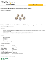
Electric motor installation:
There are two basic types of electric motor
installations. Firewall mounted for
outrunner motors like Axi and Plettenberg,
and nose ring mounted with a rear support
for inrunner motors like Hacker and Neu
motors both with reduction gearing.
Firewall mount:
For a firewall mounted motor setup you will
use the smaller of the two firewalls, the one
with the cooling holes precut. It will mount
further forward than the glow firewall.
Once the firewall is installed the only way to
install and remove the motor will be through
the opening in the nose ring. So the first
step is to open the nose ring opening enough
to slide your motor through it.
Before opening
After opening
Motor clearance
There is a hole drilled near the center of the
firewall but offset slightly. This is the center
of the motor axis when the firewall is in-
serted with the hole offset to the plane's left
which makes up for the built in right thrust.
Unless your motor is significantly different
in size from the standard outrunners it
should be used to center your motor mount.
Firewall with motor mount:
The motor or mount should have threaded
attachment points so that it can be screwed
in from the back of the firewall. Attach your
motor mount and motor to the firewall and
slide the whole unit in from the rear. You
will find that the motor will fall short of its
final position. The Plettenberg Evo shown
in the pictures was about several mm from
where it needed to be. Use your spinner
back plate to keep the motor centered and
sand away the edges of the firewall that are
contacting the fuselage. Keep fitting the
firewall. It should slip in a little further each

Page 20
Instruction Manual “Valiant” (Draft Version)
CARF-Models Co., Ltd, Contact email: [email protected]
time. Do your final fitting with your choice
of spacer between the fuse and spinner. A
plywood ring just smaller than the front of
the fuselage works best. The front of the
fuse has the proper right and downthrust
molded into it. A 1/16” space is all that is
needed with an electric motor. Once you are
satisfied that the firewall is properly fitted
and not causing any bulging to the fuse sides
you can glue it in with 30 min epoxy mixed
with micro balloons. Tape the spinner to the
fuse to hold the firewall in alignment while
the glue sets. After it hardens remove the
motor and fill in any gaps between the fuse
and the firewall and add small epoxy - micro
balloon fillets.
The precut openings in the firewall can be
opened a little bit further to reduce weight
without sacrificing strength. The firewall
started at 41 gms and finished at 34 gms
ready to install.
Electronics installation:
The speed controller can be mounted to the
side of the front of the fuse, the floor in front
of the battery packs or the back of the
firewall if you need the weight moved as far
forward as possible. Just make sure that it
stays cool enough on your first flights.
Reposition for better airflow over it if
needed.
Additional electronics, your receiver, battery
pack and regulator can be mounted to the
sides of the fuse with Velcro. A small 2 cell
lithium poly battery pack and regulator
weigh less than a standard 4 or 5 cell air-
borne pack. They can also be mounted just
behind the gear supports on the panel that
makes up the rear wall of the chin cowl
cutout.
(One of Jason's Pics)
Air outlet:
There is no air outlet from the fuse so ex-
haust holes have to be cut. Any design or
pattern will do as long as they are large
enough. The Valiant has a nice ridge molded
in the bottom of the fuse that adds additional
/