LEFTY MAX PBR 130mm
Owner’s Manual Supplement
122168.PDF
Please note that the specications and information in this manual are subject to change for product
improvement. For the latest product information, go to http://www.cannondale.com/tech_center/
SAFETY INFORMATION ............................... 2
Intended Use ............................................... 2
Front Brake .................................................. 2
Fork Damage ............................................... 4
SPECIFICATION ............................................... 4
ADJUSTMENTS ................................................ 6
MAINTENANCE .............................................18
Cleaning ........................................................ 9
Wheel Removal.........................................10
Wheel installation ....................................11
Telescope Grease .....................................12
Air Filter Cleaning ....................................13
Bumper Replacement ............................13
Needle Bearing Reset ............................14
DAMPING CARTRIDGE ................................16
XC3 STEMSTEERER ......................................18
OWNER RECORD ...........................................20
CONTENTS
WARNING
This supplement may include procedures beyond the scope of general mechanical aptitude. Special
tools, skills, and knowledge may be required. Improper mechanical work increases the risk of an
accident. Any bicycle accident has risk of serious injury, paralysis or death. To minimize risk we strongly
recommend that owners always have mechanical work done by an authorized Cannondale retailer.
READ THIS SUPPLEMENT AND YOUR CANNONDALE BICYCLE
OWNER’S MANUAL CAREFULLY! Both contain important safety
information. Keep both for future reference.

2
safety
information
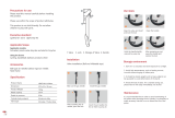
Intended Use
Lefty PBR 130mm is intended for
Condition 4 (All Mountain) riding. Condition
4 symbol shown next gure.
For riding on
rough trails
with medium
obstacles
Not Intended
The Lefty PBR 130 are not intended for use
in extreme forms of jumping/riding such as
hardcore mountain, Freeriding, Downhill,
North Shore, Dirt Jumping, Hucking etc.
WARNING
UNDERSTAND YOUR FORK AND ITS
INTENDED USE. USING YOUR FORK THE
WRONG WAY IS DANGEROUS.
Industry usage Conditions 1 - 5 are
generalized and evolving. Consult your
Cannondale Dealer about how you intend
to use your bike.
Please read your Cannondale Bicycle
Owner’s Manual for more information
about Intended Use and Conditions 1-5.
Front Brake
WARNING
DO NOT RIDE WITHOUT A PROPERLY
MOUNTED, ADJUSTED, AND
FUNCTIONING FRONT BRAKE SYSTEM.
The Lefty (disc/caliper) acts as an integral
secondary wheel retention system. If the
system is missing or improperly installed,
or if the wheel hub axle bolt should loosen,
the front wheel could slide o the spindle
end.
When mounting IS compatible brake
systems:
Follow brake manufacturer’s instructions
when mounting the brake caliper to the
spindle brake bosses. Do not modify the
fork in any way.
PLEASE ASK YOUR CANNONDALE
DEALER FOR HELP WHEN INSTALLING
COMPATIBLE FRONT BRAKE SYSTEMS.
Make sure the brake disc can not make contact
with the fork boot. A rotating brake disc can
wear through the boot allowing contaminants
into the fork.
CAUTION
USE ONLY 16mm (Cannondale kit #
LEFTYBOLTS. Longer bolts can result
in contact with the brake rotor causing
severe damage. Check clearance between
the bolt tips and rotor after remounting
the caliper.

122168.PDF
3
Fork Damage
WARNING
STOP RIDING A DAMAGED FORK IMMEDIATELY. The following conditions indicate that
serious fork damage is present:
1. Any unusual “klunking” or knocking noises.
2. A change in fork travel.
3. An over-extended, elongated, or compressed boot.
4. Changes from the way the fork had been working
5. Loss of adjustment features, oil, or air leakage.
6. Crash or impact damage (deep scratches, gouges, dents, or bending)
For next items 7-10 please read Inspect For Safety in PART II, Section D. of your Cannondale
Bicycle Owner’s Manual. See figure on page 5 in this manual for inspection AREAS I-IV.
7. AREA I - Small cracks under the bolt head of upper and lower clamp bolts. This inspection
requires the removal of the bolts.
8. AREA II - Vertical cracks in the outer tube (where the races and needle bearings run). These
may show as long, straight lines perhaps several lines parallel to each other.
9. AREA III - Horizontal cracks above and below the intersection of the upper and lower
clamps with the outer tube portion of the Lefty structure.
10. AREA IV - Vertical cracks at the back of the Lefty spindle directly behind the roll-pin. This
may happen in a big event crash and the spindle twists slightly.
HAVE ANY DAMAGED FORK INSPECTED AND DAMAGE REPAIRED BY YOUR
CANNONDALE DEALER. YOU CAN BE SEVERELY INJURED, PARALYZED OR KILLED IN AN
ACCIDENT IF YOU IGNORE THIS WARNING.
The maintenance section of this supplement includes information about regular maintenance
practices that can keep your fork in good operating condition.

4
specification
TRAVEL 130mm
INTENDED USE CONDITION 4 See page 2.
RECOMMENDED SAG
25-30% 32.5-39.0mm
AIR PRESSURE LIMITS
MINIMUM
50 psi, 3.4 bar
MAXIMUM
225 psi, 15.5 bar
CLAMP WIDTH
137.6mm 4.5” Headtube
163.0mm 5.5” Headtube
ADJUSTMENTS
REBOUND DAMPING DIAL 4.5 TURNS
LOCKOUT PUSH BUTTON LOCK/RELEASE
MAIN SPRING TYPE SOLO AIR
NEGATIVE SPRING AIR AUTOMATIC

122168.PDF
5

6
adjustments
Air Pressure
For best performance, set the air pressure in your Lefty so the sag is 32.5-39mm. Sag is the
distance the fork compresses when you sit on the bike. Sag is set by changing the air pressure
in the fork. The table of values on the next page should be a good starting point. Fine tune sag
by adding or releasing air in small amounts. Add air pressure to decrease sag. Add air pressure
to decrease sag.
1. Remove the Schrader valve cap at the bottom of the fork. Attach a bicycle suspension
pump to the valve end. Pressurize the fork according to your body weight.
2. To ne tune sag. O the bike, measuring length (A). Next, have someone assist you. Sit
on the bike with your feet on the pedals and hands on handlebar as if you were in a riding
position; measure length (B), the fork compressed under your weight. To calculate the sag,
subtract : A - B = SAG (mm).
CAUTIONS
CLEAN PUMP AND VALVE ARE CLEAN.
Attaching to a dirty valve or with a dirty
pump end can result in pumping the
dirt into the fork. This could result in
damage and air loss.
DO NOT FORCE THE REBOUND DIAL
PAST THE STOP POINTS. USE ONLY
YOUR FINGERS TO TURN.

122168.PDF
7
Rebound
The red rebound dial at the top of
the fork controls rebound speed,
how fast the fork extends following
compression. There are 4 1/2 turns of
total adjustment.
Turn the dial CLOCKWISE for slower
rebound.
Turn the dial COUNTER-CLOCKWISE for
faster rebound.
Lockout
To lockout the fork - Press the small blue button down with your nger tip. This will trigger the
rebound dial to pop up. Fork travel is locked out when the dial is up. See LOCKED.
To unlock travel - Press the rebound dial down rmly. Fork travel is not locked out when the
buttons are down. See UNOCKED.
If button action begins to stick, (fork will not lock easily) it is likely due to dirt in the rebound and
lockout knob seals. Remove the at head screw in the center of the blue lock button. Pull the red
rebound knob o the fork and remove the lock button and clean and grease the seal inside the
upper collar and inside the rebound knob.

8
maintenance
This schedule is intended as a guide only. You must establish a schedule appropriate to your
riding style and conditions.
WHAT TO DO
NORMAL RACE
(In Hours)
CHECK FOR DAMAGE
Don’t ride if damage is found. See page 3.
BEFORE AND AFTER EVERY RIDE
CHECK THE BOOT
Replace the zip ties if loose.
CHECK TIGHTENING TORQUES
Upper/Lower clamp bolts: 9.0 Nm
Wheel Axle Bolt: 15.0 Nm
AFTER FIRST RIDE
CHECK EVERY 4-5 RIDES
Grease telescope. 50 25
Needle Bearing Reset*
25 25
Clean air lter
25 10
Damping cartridge oil and seal change* 100 25
Inspect, Replace Bumper
AS NEEDED
PROFESSIONAL SERVICE* ANNUAL (Minimum)
Annually, or when problems are indicated you must have your Lefty fork serviced through
a Cannondale Dealer or an Authorized Headshok Service Center. Your fork should
be disassembled by a suspension professional and evaluated for internal and external
part wear and damaged parts replaced with new ones. It should also include any work
described in any technical bulletins or product recalls.
WARNING
FREQUENT MAINTENANCE AND INSPECTION IS IMPORTANT TO YOUR SAFETY. YOU
CAN BE SEVERELY INJURED, PARALYZED OR KILLED RIDING ON A BROKEN OR POORLY
MAINTAINED FORK. Ask your Cannondale Dealer to help you develop a complete fork
maintenance program, one that suits where and how you ride.

122168.PDF
9
Riding in Wet, Humid, or Coastal Conditions
Before and after rides, frequently, inspect and renew grease under fork boot
and service the air lter. Inspect the boot for rips and tears. Check the folds.
If the boot is damaged or not attached securely by the clamps/zip ties ,
water or contaminants can enter. The boot should be removed and the fork
should be immediately dried and re-greased to stop any damage occurring
due to moisture.
ANYTIME THE FORK BECOMES SUBMERGED
Stop riding it. The fork is not water tight. A moving submerged fork can
accumulate water inside. If your fork has been submerged, you should
perform checks immediately.
DO NOT STORE YOUR LEFTY FOLLOWING A WET RIDE WITHOUT FIRST
PERFORMING THE CHECKS ABOVE. SERIOUS DAMAGE CAN OCCUR.
Cleaning
Clean using only a mild soap and water solution. Clean water and common liquid dish washing
soap will work best. Be sure to cover the adjusters with a clean plastic bag secured with a rubber
band or masking tape. Spray o heavy dirt before wiping. Spray indirectly.
CAUTION
DO NOT USE A PRESSURE WASHER. Use a low pressure garden hose. Power washing will
force contaminants into the fork promoting corrosion, immediately damaging, or result in
accelerated wear. Don’t dry with compressed air for the same reason.
PLEASE NOTE
Cannondale provides professional services through Cannondale dealers for Headshok /Lefty
suspension forks. Please ask your dealer about the service programs available for your model
fork.

10
Wheel Removal
1. Loosen the brake caliper mounting bolts.
Tilt the lower caliper bolt out of the
boss so the caliper is up out of the
way of the disc. Snug up on the
upper bolt to hold caliper in place.
Take note of brake alignment shims
between brake bosses and the caliper. Be
sure to reposition correctly.
2. Turn the hub extraction bolt counter-
clockwise (ccw) to remove the wheel.
CAUTION
1. Make sure the bolt is completely
disengaged before attempting
to remove the wheel. Never try
to pull the wheel o forcefully.
2. When the wheel is o, to keep
dirt out, cover the hub opening.
3. Protect spindle from damage
when wheel is removed.
Continue turning the bolt until the wheel
can be removed easily from the spindle.

122168.PDF
11
Wheel Installation
1. Inspect inside the wheel hub for
contamination and and the condition
of the hub seal. Take corrective action if
necessary.
Wipe the spindle clean with a dry shop
towel and apply a high-quality bike grease
to the spindle bearing lands and end
threads. See next Figure.
2. Slide the wheel straight onto the spindle
so, the larger hub bearing starts to position
on it spindle seat. At this point, the axle
bolt threads can correctly engage the
threaded spindle if the wheel is held on
straight.
NOTE: Install the front wheel by positioning
the bike horizontally with the spindle facing
up. Then place the hub straight down onto
the spindle, and tighten the axle bolt.
3. When the axle bolt threads engage the
spindle, turn the bolt clockwise with nger
force slowly to allow the hub bearings
to slide onto the spindle bearing seats.
Once the hub has been drawn onto the
hub completely, use torque wrench to
tighten to nal 15.0 N•m (133.0 In•Lbs).
4. Reinstall the brake caliper. Tighten bolts to
78.0 In•Lbf (9.0 N•m).
5. Spin the wheel to make sure it moves
freely. Be sure to test the brakes for
proper operation before riding.
WARNING
Do not contaminate brake caliper, pads,
or rotor with grease.
CAUTION
LOCATE DISC BETWEEN THE PADS.
Replace shims that are in use, be sure the
shims are positioned between the caliper
(adapter if any) and inner face of the fork
mounts, not under the head of the caliper
bolts.
USE ONLY 16mm (Cannondale kit #
LEFTYBOLTS. Longer bolts can result
in contact with the brake rotor causing
severe damage. Check clearance between
the bolt tips and rotor after remounting
the caliper.

12
Grease Telescope
1. Remove the front wheel.
2. Carefully release the upper and lower zip
ties securing the fork boot. If the boot is
secured with a band clamp, loosen and
remove them.
3. Lift the unsecured boot up to expose the
inner tube.
4. Wipe o the old grease with a dry shop
towel.
5. Re-apply a fresh heavy coating of grease.
Any clean high-quality bicycle bearing
grease selected for riding temperatures
and environment can be used.
We assemble forks at our factory
using Royal Purple Ultra Performance
Grease NLGI #2 (ISO 46 BASE).
Cycle the fork several times between
applying grease to the new grease is
worked into the bearings.
6. Reposition the boot and replace the zip
ties. Make sure the zip ties are very tight.
Loose zip ties may allow water or dirt to
pass behind the boot.
WARNINGS
CHECK THE BOOT BEFORE EACH RIDE.
DON’T RIDE IF IT IS DAMAGED.
HAVE IT REPLACED WITH A NEW ONE.

122168.PDF
13
Air Filter
To clean, release the upper and lower clamps or zip tie and slide the lter cover up o the foam.
Slide the foam up the outer tube and cover the two small holes in the outer tube to prevent
water from getting inside the fork. Clean with warm soapy water. Rinse with clean water and
allow the foam to dry completely. Then, massage in a high-quality foam air lter oil before re-
assembly.
NOTE: The small holes at the base of the lter cover should remain clear and be positioned to
the sides of bike and not to the front or back to minimize the chance dirt thrown by the wheels
will plug the holes.
Bumper Replacement
Replace the frame bumper with a new one if it ever becomes damaged, torn, or missing. To
remove it, remove the band from the bumper groove and unwrap the bumper.
NO. ORDER NO. KIT DESCRIPTION
1 KF209/ KIT,COLLAR,LOWER,CRB,CLIP+BUSH
2
HDR2M/020
RACE INNER 11.378 X .020in [289.0 X .53mm]
(Qty 4)
HDR2M/021
RACE INNER 11.378 X .021in [289.0 X .56mm]
(Qty 4)
HDR2M/022
RACE INNER 11.378 X .022in [289.0 X .58mm]
(Qty 4)
HDR2M/023
RACE INNER 11.378 X .023in [289.0 X .61mm]
(Qty 4)
HDR2M/024
RACE INNER 11.378 X .024in [289.0 X .635mm]
(Qty 4)
3 HD161/ LEFTY NEEDLE BEARINGS (QTY 4)
4 HDR2N/024 RACE OUTER

14
Needle Bearing Reset
Needle bearing resets must be performed as maintenance. Migrated needle bearings are
bearings that are no longer aligned together. Riding a fork with migrated needle bearings for
extended periods can result in damage.
TO BE PERFORMED ONLY BY A PROFESSIONAL BIKE MECHANIC:
Annually as part of your annual fork overall maintenance. See schedule on page 8.
Whenever free length is less than specied
If the fork produces a top out noise when fully extended
If normal fork travel becomes reduced
To reset
1. Release all air pressure through Schrader valve in bottom of fork.
2. Remove the outer collar the Shimano tool TL-FC32. Turn counter-clockwise.
3. Compress the telescope and remove the two split rings from the top cap.
4. Fully extend the fork, and measure from top edge of outer tube to bottom edge of spindle.
See right. If the length is out of specication do the following:
Firmly extend the telescope until it stops (tip - listen for the knocking at full extension to change
from a hollow sound to a solid sound - this indicates full extension has been achieved). Do this
several times using only moderate force, extend the lower fork leg using a pumping action.
After, you have performed this action several times, re-measure.
CAUTION
If fork is out of range following reset attempt, it may be damaged internally. The fork
should be disassembled and inspected by a professional mechanic before it is ridden.
5. Reassemble.
NOTE: If migration re-occurs frequently (immediately after resetting), the cause could be
damage present in the inner or outer races, bearings/cages or other fork parts. Inspection
and replacement of damage parts will be required to correct a persistent problem with
bearing migration.

122168.PDF
15
RESET BY FULLY
EXTENDING LOWER
LEG
NEEDLE BEARINGS
INSIDE THIS PART
OF FORK.
4 NEEDLE BEARING CAGES

16
NO. DESCRIPTION
1 SPECTRO 85/150 OIL (cc)
2 2-006 O-RING 2.90 ID X 1.78 W
3 2-010 O-RING 6.07 ID X 1.78 W
4 2-011 O-RING 7.65 ID X 1.78 W
5 2-012 O-RING 9.25 ID X 1.78 W
6 2-013 O-RING 10.82 ID X 1.78 W
7 2-014 O-RING 12.42 ID X 1.78 W
8 2-018 O-RING 18.77 ID X 1.78 W
9 2-112 O-RING 12.37 ID X 2.62 W
10 2-117 O-RING 20.29 ID X 2.62 W
11 O-RING 2.00 ID X 1.00 W
12 O-RING 9.00 ID X 1.00 W
13 O-RING 8.00 ID X 1.50 W
14 SHCS M2 5 X 5
15 BLEED SCREW M2 5 X 4 FHP
16 SFHS M X 8
17 COMPRESSION SHIM STACK (SEE TABLE)
18 REBOUND SHIM STACK (SEE TABLE)
19 CHROME STEEL BALL 3MM
20 DLR 110 OIL CAP
21 DLR 110 PRESSURE COMP PISTON
22 DLR 110 PRESSURE COMP SPRING
23 DLR 110 PISTON SPACER
24 DLR 110 BUMPER
25 DLR 110 PISTON RING
26 DLR 110 MAIN PISTON
27 DLR 110 OIL CYLINDER WASHER
28 07 DLR 100 OUTER CAP
29 BALL LOCK UPPER SHAFT
30 BALL LOCK POPET
31 BALL LOCK INNER SHAFT
32 BALL LOCK KNOB SHAFT
33 BALL LOCK REBOUND KNOB
34 BALL LOCK RELEASE BUTTON
35 BALL LOCK THRU SHAFT
36 BALL LOCK LOCKOUT PISTON
37 BALL LOCK LOCKOUT ROD
38 BALL LOCK NEEDLE PINNED
39 BALL LOCK PISTON CONNECT
40 BALL LOCK LOWER SHAFT 130
41 BALL LOCK CONNECT BUSHING
42 SOLO AIR MAIN PISTON R3
43 SOLO AIR PISTON SUPPORT R3
44 SOLO AIR UPPER SEAL 130
45 SOLO AIR BUMPER PLATE
46 SOLO AIR NEGATIVE BUMPER
47 RETAINING RING EXT. M10
48 PIN ROLL M2 x 10
49 M1.6 x 16 PAN HEAD SCREW
50 LOCKOUT ROD SPRING
51 BALL LOCK SPRING RELEASE
52 #5 WASHER
53 CRESENT SHAPE SPRING WASHER
54 BALL LOCK OIL CYLINDER 130
55
1/2” U-CUP PARKER
#N4180-A80-8404-00500
56 WASHER
57 SPLIT RING
NO. ORDER NO. KIT DESCRIPTION
KH041/ 130 PBR CARTRIDGE
HD226/ GOLDEN SPECTRO 1 US QT.
2, 3, 4, 5, 6, 7, 8, 9, 10, 11, 12, 13,
15, 55
KH042/ PBR 130 SEAL KIT
4, 7, 9, 10, 42, 43, 44, 45, 46, 47, 53 KH043/ PBR 130 AIR PISTON KIT
6, 16, 33, 34 KH044/ PBR 130 KNOBS
57 KF205/ 2 SPLT RINGS
58 HD187/ 1/2” SHAFT CLAMP
59 HDTL168/ OIL CAP INSTALL
60 KH004/ OIL CAP WRENCH
61 HDTL146/ CARTRIDGE REMOVAL
SHIM STACKS FROM PISTON OUT
COMPRESSION REBOUND
16 X 0.152 18 X 0.102
18 X 0.102 16 X 0.102
14 X 0.152 14 X 0.102
AIR SPRING VOLUMES:
MAIN SPRING = 94905mm^3
NEGATIVE SPRING = 33405 mm^3
EFFECTIVE LENGTH:
MAIN SPRING = 190.0mm
NEG SPRING = 66.9mm
Assembly Note
NLGI 2 synthetic grease is to be applied to all seal
grooves, surfaces, and glands.
CANNONDALE CARTRIDGE TOOLS
DAMPING CARTRIDGE

122168.PDF
17

18
xc3 stem-steerer
The following procedure should be completed
by a professional bike mechanic.
Installation
1. Loosen both clamp bolts .
3. Position the Lefty clamps onto the
headtube assembly as shown.
4. Insert Cannondale tool KT020/ through the
bottom clamp, into the head tube, and out
the upper clamp.
5. Make sure the plastic ring is on the stem.
Insert the bottom of the stem-steerer onto
the top of the tool.
6. Remove the cap from the top of the
steerer. Use a rubber mallet to drive the
stem-steerer into the head tube until it
stops. Return the cap.
7. Clean and apply grease to the steerer bolt
threads and install into the bottom of the
stem-steerer. The bolt is a structural part
that threads into the bottom of the stem-
steerer. Align handlebar and tighten the
bolt to 9 N•m.
8.. Tighten the upper and lower clamp bolts
to 9 N•m.
Removal
1 Loosen upper and lower clamp bolts.
2. Remove steerer bolt. Use a 5mm Allen key;
turn counter-clockwise.
3. Insert the small end of KT020/ into the
bottom of the stem-steerer and drive the
stem-steerer up out of the head tube.

122168.PDF
19
WARNING
The steerer bolt is a structural
part and must be installed.
NOTES:
1. When removing or installing
steerer bolt, insert 5mm Allen key
completely to prevent stripping the
bolt.
2. The drain hole enables accumulated
moisture to drain out. Use a
toothpick to keep it clear.
XC3 Stem-Steerer kits in
various sizes are available
through your Cannondale
Dealer.

20
owner record
Record maintenance history, service, or set up information .
DATE WORK PERFORMED
/