Page is loading ...

INSTALLATION &
OPERATION MANUAL
IPSi365
INTELLIGENT
PURE-SINE
INVERTER
8128 River Way, Delta B.C. V4G 1K5 Canada T. 604.946.9981 F. 604.946.9983 TF. 800.668.3884 (US/CANADA)
www.AnalyticSystems.com
An ISO9001 Registered Company Battery Chargers • Inverters • Power Supplies • Voltage Converters

2
MEDICAL EQUIPMENT NOTICE
Analytic Systems does not recommend the use of their products in life support
applications where failure or malfunction of this product can be reasonably expected to
cause failure of the life support device or to signicantly affect its safety or effectiveness.
Analytic Systems does not recommend the use of any of its products in direct patient
care. Examples of devices considered to be life support devices are neonatal oxygen
analyzers, nerve stimulators (whether used for anesthesia, pain relief, or other purposes),
auto-transfusion devices, blood pumps, debrillators, arrhythmia detectors and alarms,
pacemakers, hemodialysis systems, peritoneal dialysis systems, neonatal ventilator
incubators, ventilators for both adults and infants, anesthesia ventilators, and infusion
pumps as well as any other devices designated as “critical” by the U.S. FDA
DANGER: Never alter the AC power cord or plug provided. If it will not t the output, use
an approved adapter or have the proper AC power cord installed by a qualied electrician.
Improper connection can result in the risk of electric shock.
INVERTER
IMPORTANT SAFETY INSTRUCTIONS
SAVE THESE INSTRUCTIONS — This manual contains important safety instructions for
operating the Inverter.
INVERTER PRECAUTIONS
1. Do not expose the Inverter to rain or snow unless it is a sealed model.
2. Do not use any attachments with the Inverter unless recommended or sold by the manu-
facturer, this may result in a risk of re, electric shock, or injury to persons.
3. Do not disassemble the Inverter; if service or repair is required, return it to the manu-
facturer or an authorized service center. Incorrect reassembly may result in a risk of re,
electric shock, or injury to persons. Voltages in excess of 350 volts are present inside the
charger any time it is plugged into an AC outlet, even if switched off.
4. To reduce risk of electric shock, unplug the Inverter from the AC power before attempting
any maintenance or cleaning. Turning off controls will not reduce this risk.
5. Do not place Inverter directly above a battery; gases generated by battery will corrode
and damage Inverter.
6. Do not allow battery acid to drip on the Inverter.
GROUNDING AND AC POWER CORD CONNECTION INSTRUCTIONS
The plug must be plugged into an outlet that is properly installed and grounded in accordance
with all local codes and ordinances.
HEAVY DEVICE - The IPSi1000, 2000 and 3000 Inverters weigh more than 30lbs (13.6kg).
Please use appropriate safety measures when lifting or moving these units.

3
TABLE OF CONTENTS
• Front Cover, Product Photo and Title
• Product Warnings and Advisories
• Table of Contents
• Introduction / Box Contents
• Main Parts
• Operation
• Controls and Indicators
• Installation
• Input Connections / Output Connections
• Ofine UPS Option
• InverterWizard
• Troubleshooting
• Specications
• Warranty
Revised - August 19, 2019
Copyright Analytic Systems Ware (1993) Ltd.

54
Introduction
The IPSi365 series of Intelligent Pure Sinewave Inverters are designed specically for
powering computers and other sensitive AC loads in rugged, mobile, off-grid environments.
They produce pure sinewave AC power, identical to a conventional AC outlet.
Internally, the IPSi365 is controlled by a sophisticated Digital Signal Processor (DSP) for
optimal control and the most efcient operation possible. The heavy-duty Toroidal Power
Transformer steps the low voltage AC produced by the Power MOSFET Transistors to 110 or
220 VAC at 50 or 60 Hz. Additional ltering on the AC output reduces or eliminates EMI noise
that can interfere with sensitive communications equipment.
Built for the safest operation possible, this unit features low voltage warning with shutdown
circuitry to protect the DC power source. While the inverter is safeguarded by high voltage
and over temperature protection both with shutdown circuitry. All the alarm conditions can
be monitored on the bright LED indicator display which can also be mirrored on the optional
remote control panel.
Using the free-to-download InverterWizard software from Analytic Systems, you can change
the output frequency, adjust the voltage shutdown thresholds and view and record operating
data from any PC with a standard USB interface.
The box you have received should contain the following:
• 1 IPSi365 Intelligent Pure Sine Inverter
• 1 compatible USB cable
• 1 Warranty Card
• This User Guide (A PDF copy can be downloaded from www.analyticsystems.com)
• Optional InverterWizard software can be downloaded from www.analyticsystems.com
Box Contents
If anything is missing or damaged please contact your dealer or Analytic Systems for a replacement.

54
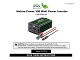
1. Remote Control Connection
2. USB Communications Port
3. AC Output Connection 1: NEMA
5-15 Outlet
4. AC Output Connection 2: Color-
coded Phoenix VFDK Terminal Blocks
(Gray: AC Neutral, Green: AC Ground,
Black: AC Hot)
5. Power Switch
6. DC Input Connection: Color-
coded Phoenix VFDK Terminal
Blocks (Red: DC Positive, Black
DC Negative)
Main Parts
1
2
2
1
6
3
Front Panel
1. Indicator LEDs
Top Chassis
2. Unit Label
4
5

76
Operation
This unit is designed for simple operation. Before operating, the inverter must be properly
installed and connected. See Installation and AC/DC Connections for more information.
TO OPERATE THE INVERTER:
1. Move the Power Switch to ON to energize the circuitry.
2. The Invert LED and either the 50 Hz or 60 Hz LED will glow green indicating proper
operation and the presence of AC power at the outputs.
3. The inverter will automatically begin supplying the connected load with voltage and
current printed on its label.
TO END OPERATION:
1. Move the Power Switch to OFF to end operation.
2. Wait for all the LEDs to turn off.
3. The inverter can now be safely disconnected from the load and power source. It can then be
serviced or put into storage.

76
Operational Indicators
There are eight LED indicators on the inverter’s top chassis which display the unit’s operating
condition. The table below details their meaning:
LEDs Meaning
LOW
VOLTAGE
• Blinks red when the input voltage nears the minimum limit for operation.
• Glows red when the input voltage is too low for operation. The Bypass LED will
also glow red and the Invert LED will turn off.
• The shutdown and start-up thresholds for the low voltage alarm can be
adjusted using InverterWizard. See InverterWizard for more information.
HIGH
VOLTAGE
• Blinks red when the input voltage nears the maximum threshold for operation.
• Glows red when the input voltage is too high for operation. The Bypass LED
will also glow red and the Invert LED will turn off.
OVER TEMP • Blinks red when the unit’s internal temperature nears the safe limit. The
inverter will automatically derate its maximum power rating to try to
maintain a safe operating temperature.
• Glows red when the inverter is too hot to operate. The Bypass LED will
also glow red and the Invert LED will turn off.
OVER LOAD • Blinks red when the current being drawn reaches the unit’s continuous rating.
• Glows red when the current being drawn reaches the unit’s peak rating.
50 HZ • Glows green if the inverter’s output frequency is set to 50.00 Hz. This
setting can be changed using InverterWizard.
• If the alarm sounds and both the 50 Hz and 60 Hz LEDs glow red. The unit
is experiencing a ground fault and the Ground Fault Interruptor has shut
down the unit.
60 HZ • Glows green if the inverter’s output frequency is set to 60.00 Hz. This set-
ting can be changed using InverterWizard.
• If the alarm sounds and both the 50 Hz and 60 Hz LEDs glow red. The unit
is experiencing a ground fault and the Ground Fault Interruptor has shut
down the unit.
BYPASS • Glows green if the inverter is in Bypass mode and functioning as an Off-line
Uninterruptible Power Supply. For more information, see Off-line UPS.
• Glows red when the inverter is experiencing a malfunction.
INVERT • Glows green when the inverter operating normally.

98
MOUNTING
Mount the unit in a DRY and WELL
VENTILATED area. Allow at least one inch
(2.54 cm) of clearance all around the unit
for adequate cooling.
CAUTION: DO NOT MOUNT THE UNIT
ANYWHERE EXPLOSIVE GASES CAN
ACCUMULATE.
A slight arc may occur when the power
leads are connected, and in the unlikely
event of a failure, sparks may be
generated inside the unit.
Installation
IMPORTANT: BEFORE CONNECTING OR DISCONNECTING ANYTHING TO THE
INVERTER, MAKE THE UNIT IS OFF.
GROUNDING
The unit case is connected to AC Ground and AC Neutral in order to meet regulatory
requirements and reduce the possibility of it generating any radio frequency interference.
The unit case must be bonded appropriately to the grounding system of the vehicle or marine
vessel. On a vehicle, bond the case to the vehicle’s frame. On a marine vessel, bond the case
to the vessel’s hull. A grounding stud is provided on the front panel for this purpose.
To ensure proper grounding, check the connection with an ohmmeter. The case is isolated from
the DC input, so the DC power can be connected to a different ground from the AC output.
DISCONNECTING
If you need to disconnect the Inverter for service or storage:
1. Move the power switch to OFF and disconnect the DC power source.
2. With power disconnected, move the power switch to ON.
3. Leave the switch in this position for one minute to discharge the storage capacitors.
4. Return the power switch to the OFF position. Disconnect the load(s).
5. The inverter is ready for service or storage.

98
This unit is also equipped with a NEMA 5-15 AC outlet as a secondary AC Output Connection.
This outlet is identical to a North American AC Mains outlet. This unit can also be constructed
with a European AC or Worldwide AC mains compatible outlets by custom order.
CAUTION: DO NOT APPLY AC VOLTAGE TO
ANY AC OUTPUT CONNECTION.
This will damage the inverter and will not be
covered under warranty.
DC Input Connections
AC Output Connections
DC INPUT POWER CONNECTION
This unit is equipped with a pair of color-coded Phoenix VDFK6 terminal block connectors to
serve as a DC Input Connection.
Connect the DC input power here using AWG8/10mm
2
wire. The wires should be stripped
0.4 inches/9mm and tightened securely to 16 inch-pounds/1.8 Newton Meters. The terminal
blocks are color-coded to indicate polarity which is as follows:
AC OUTPUT CONNECTION
This unit is equipped with three color-coded Phoenix VDFK4 terminal block connectors to serve
as a hard wired AC Output Connection.
Connect the AC load here using wires from AWG24/0.25mm
2
to AWG10/ 6mm
2.
The wires
should be stripped 0.3 inches/ 8mm and tightened securely to 16 inch-pounds/1.8 Newton
Meters. The terminal blocks are color-coded to indicate polarity which is as follows:
NA 220VAC 60HZ
- part code“U”-
WW 220VAC 50HZ
- part code“W”-
Connector Color Polarity
Black AC Hot/Live
Gray AC Neutral
Green/Yellow AC Ground (Chassis)
Connector Color Polarity
Red DC Input Positive
Black DC Input Negative
CAUTION: DO NOT REVERSE CONNECT THE DC INPUT POWER
This will damage the inverter and will not be covered under warranty.

1110
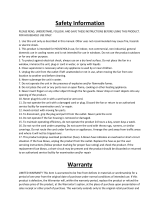
Off-line UPS (Optional)
The Off-line UPS (Uninterruptible Power Source) option allows the inverter to function as a
backup power source in the event of external AC power failure.
Legend
AC Power Source
DC Power Source
Inverter
Load
Battery Charger
AC Current
DC Current
NORMAL OPERATION
• The AC power source supplies AC
power to both the battery charger
and the load (Running through the
inverter’s off-line).
• The battery charger supplies DC power
to a battery, maintaining it at full charge.
This battery is connected to the inverter’s
DC Input Connection(s).
Legend
AC Power Source
DC Power Source
Inverter
Load
Battery Charger
AC Current
DC Current
AC POWER FAILURE
• The inverter detects a drop in AC
voltage and starts operation.
• The inverter draws DC power from the
connected battery which inverts it to
AC power to supply the load.
• The inverter continues operating until
it detects that the AC Voltage has been
restored or the battery is discharged.
TO SET UP THE OFF-LINE UPS:
1. Connect the AC power source to the AC Input Connection.
2. Connect the DC power source (batteries) to the DC Input Connection.
3. Connect the load to the AC Output Connection.
4. Turn the inverter ON. The Bypass LED will glow green indicating the load is being
supplied with power from the AC power source through the inverter’s off-line.
5. If the AC power fails, the Bypass LED will turn off and the Invert LED and 50/60Hz LED will
glow green indicating the Inverter is operating.
The AC input voltage thresholds for the inverter to take over supplying and to end supplying AC
power can be changed using InverterWizard to t your specic needs. For more information, see
the InverterWizard manual.
TIP: MAKE SURE THE BATTERIES HAVE WITH ENOUGH CAPACITY TO POWER THE
LOAD FOR THE REQUIRED AMOUNT OF TIME IN THE EVENT OF AC POWER FAILURE.
For example, a 2000 watt Inverter with 24 VDC input will draw ~100 A, so for 2 hours of
runtime the minimum required battery capacity is 280 amps-hours @ 24 volts.

1110
InverterWizard (Optional)
InverterWizard is optional software that can be used to adjust the inverter’s operating
settings. InverterWizard is free-to-download from www.analyticsystems.com or available by
emailing [email protected]
Using InverterWizard, you can:
• Set the inverter’s output frequency to either 50.00 or 60.00 Hz.
• Adjust the inverter’s output voltage over a ±10% range in 1 VAC intervals.
• Set the voltage thresholds for the low voltage alarms.
• Set the voltage thresholds for UPS function to start and stop.This function is only
available on units with the UPS option. See Off-line UPS for more information.
• Update the inverter’s rmware.
• Monitor and record the inverter’s operating data.
ALTERNATE DC VOLTAGES AND LOW VOLTAGE SHUTDOWN
IPSi series Intelligent inverters are factory-preset for the low voltage alarm/shutdown to
trigger if the unit detects an input voltage drop of:
• <12 VDC for a -12 model
• <24 VDC for a -20 model
• <48 VDC for a -40 model
If the inverter uses an alternate input voltage such as 32 VDC, 36 VDC, or 72 VDC (rail) battery
then the low voltage shutdown thresholds will need to be adjusted using InverterWizard.
NOTE: INVERTERWIZARD IS NOT REQUIRED TO OPERATE THE INVERTER.
The inverter can immediately be put into service if its default operating settings are suitable
for your needs. The inverter’s default settings are listed its label.

1312
Troubleshooting
This unit features eight LED indicators and an alarm buzzer to help diagnose any malfunctions.
In the event of malfunction, the inverter will sound the buzzer to alert you prior to shutting
down its output. You should immediately check which LEDs are glowing to determine the
cause of the malfunction.
LED / Issue Meaning
LOW VOLTAGE LED is ON The input voltage is too low for normal operation.
Fix: Check that the power source is appropriately rated for the application.
Check that the input wiring and connections are not corroded or dam-
aged.
If using InverterWizard, check the Low Voltage Alarm parameters are
properly set for the voltage of battery you are using, for example: 21V for
a 24V battery and 28V for a 32V battery.
If the above are checked and in working order, the cause is likely an
internal component failure and the unit must be returned for repair.
HIGH VOLTAGE LED is ON The input voltage is too high for normal operation.
Fix: Check that the power source is appropriately rated for the application
The inverter can be damaged if the input voltage exceeds the rating indi-
cated on the label. Over-voltage damage is not covered under warranty.
If the above are checked and in working order, the cause is likely an
internal component failure and the unit must be returned for repair.
OVER TEMP LED is ON The unit’s internal temperature is too hot for normal operation.
Fix: Check that the unit’s cooling fans are functioning. If the fans are run-
ning, you may need to remount the Inverter for improved ventilation.
The inverter will automatically derate its max. power rating to try to
maintain a safe operating temperature. If the internal temperature
exceeds the safe maximum, the unit will shut off its outputs. When the
temperature drops to safe operating range, the inverter will autorecover.
If the fans are NOT running,the unit must be returned for repair.
OVER LOAD LED is ON The load is drawing too much current from the inverter.
Fix: The unit has been operating at peak current for longer than its
intended duty cycle. Reduce the load by disconnecting some devices
from the unit’s AC output.
TIP: FOR QUICK REFERENCE, IF THE UNIT IS EXPERIENCING A MALFUNCTION THE
INVERT LED WILL BE OFF AND ALSO THE BYPASS LED WILL GLOW RED.

1312
Specications
Input -12 -20 -40
Nominal Voltage 12 VDC 24, 28, 32, or 36 VDC 48 or 72 (Rail) VDC
Actual Voltage 10.5-18 VDC 19 - 48 VDC 39 - 84 VDC
Input Amps (Max.) 49 A 24 A 12 A
Input Fuse (Internal) 2x 30A 32 VDC Blade Mini 1x 30A 58 VDC Blade Mini 1x MDA - 15A fuse
Under Voltage Input Alarm
Shutdown Range
10.5-14 VDC
(Default setting: 10.5 VDC)
19-36 VDC
(Default setting: 21 VDC)
39-70 VDC
(Default setting: 42 VDC)
Under Voltage Input Alarm
Start-up Range
11-14 VDC
(Default setting: 11VDC)
20-36 VDC
(Default setting: 23VDC)
40-70 VDC
(Default setting: 10.5 VDC)
Under Volt Input
Shutdown Delay
1-120 seconds (Default setting: 30 seconds)
Over Voltage
Input Shutdown
19 VDC 49 VDC 86 VDC
Inrush Current (From fully
discharged)
1.8 Amp Peak 4.8 Amp Peak 8.4 Amp Peak
Output -110 -220
Nominal Voltage 110 VAC 20 VAC
Continuous Amps 3 A 1.5 A
Peak Amps 3.6 A 1.8 A
Output Frequency 50.00 or 60.00 Hz ± 0.01 Hz (User-selectable)
Output Distortion (THD) <2% at 360 VA into resistive load
Regulation (Line & Load) < +/- 2.0%
Duty Cycle 100% for 24 hours per day / 1 min @ peak with 10 minute cool down
Efciency 85% @ Full load
Ground Fault Trip Current 4-6 mA

14
* Specications subjects to change without notice.
General
Length 13.0 in / 32.8 cm
Width 8.0 in / 20.3 cm (Including mounting anges)
Height 3.3 in / 8.3 cm
Clearance 1.0 in / 2.5 cm
Weight 16.0 lb / 7.3 kg
Material Marine-grade aluminum
Finish Black anodized
Fastenings 18-8 Stainless steel
Input Connections
AC: Phoenix VDFK4 32 Amp / 500V terminal block (Off-line UPS Option mandatory)
DC: Phoenix VDFK6 50 Amp / 300V terminal block
Output Connections
Hardwire: Phoenix VDFK4 32 Amp / 500V terminal block
110 VAC Model: NEMA 5-15 receptacle
220 VAC North American Model (220N): NEMA 6-20 receptacle
220 VAC Worldwide Model (200W): 220V Universal receptacle
Other Connections
Data/Communication: MicroUSB port
Remote Control: RJ45 ‘telephone jack’ connector with proprietary pinout
Environmental and Safety
Operating Temperature
-25°C to +40°C @ Full load
(Expanded -40°C to +55°C Operating Temperature Option available)
Storage Temperature -55 °C to 105°C
Cooling One internal thermostatically controlled cooling fan
Humidity 0 - 95% relative humidity (non-condensing) with standard conformal coating
Audible Noise < 27 dB @ 3 ft/ 1m with fan running
Typical Service Life > 10 Years (86,700 hours)
Isolation Input to Chassis: <1100VDC. Input to Output, Output to Chassis: <1500 VAC
Warranty 5 Years Parts and Labour
Emissions Complies with FCC Class B, Part 15

14
Limited Warranty
1. The equipment manufactured by Analytic Systems Ware (1993) Ltd. (the “Warrantor”) is warranted to be free
from defects in workmanship and materials under normal use and service.
2. This warranty is in effect for:
a. 3 Years from date of purchase by the end user for standard products offered in our catalog.
b. 2 Years from date of manufacture for non-standard or OEM products
c. 1 Year from date of manufacture for encapsulated products.
3. Analytic Systems will determine eligibility for warranty from the date of purchase shown on the warranty card
when returned within 30 days, or
a. The date of shipment by Analytic Systems, or
b. The date of manufacture coded in the serial number, or
c. From a copy of the original purchase receipt showing the date of purchase by the user.
4. In case any part of the equipment proves to be defective, the Purchaser should do the following:
a. Prepare a written statement of the nature of the defect to the best of the Purchasers knowledge, and
include the date of purchase, the place of purchase, and the Purchasers name, address and telephone
number.
b. Call Analytic Systems at 800-668-3884 or 604-946-9981 and request a return material authorization
number (RMA).
c. Return the defective part or unit along with the statement at the Purchasers expense to the Warrantor;
Analytic Systems Ware (1993) Ltd., 8128 River Way, Delta, B.C., V4G 1K5, Canada.
5. If upon the Warrantor’s examination the defect proves to be the result of defective material or workmanship,
the equipment will be repaired or replaced at the Warrantor’s option without charge, and returned to the
Purchaser at the Warrantor’s expense by the most economical means. Requests for a different method of return
or special handling will incur additional charges and are the responsibility of the Purchaser.
6. Analytic Systems reserves the right to void the warranty if:
a. Labels, identication marks or serial numbers are removed or altered in any way.
b. Our invoice is unpaid.
c. The defect is the result of misuse, neglect, improper installation, environmental conditions, non-autho-
rized repair, alteration or accident.
7. No refund of the purchase price will be granted to the Purchaser, unless the Warrantor is unable to remedy the
defect after having a reasonable number of opportunities to do so.
8. Only the Warrantor shall perform warranty service. Any attempt to remedy the defect by anyone else shall
render this warranty void.
9. There shall be no warranty for defects or damages caused by faulty installation or hook-up, abuse or misuse of
the equipment including exposure to excessive heat, salt or fresh water spray, or water immersion except for
equipment specically stated to be waterproof.
10. No other express warranty is hereby given and there are no warranties that extend beyond those described
herein. This warranty is expressly in lieu of any other expressed or implied warranties, including any implied
warranty of merchantability, tness for the ordinary purposes for which such goods are used, or tness for a
particular purpose, or any other obligations on the part of the Warrantor or its employees and representatives.
11. There shall be no responsibility or liability whatsoever on the part of the Warrantor or its employees and rep-
resentatives for injury to any person or persons, or damage to property, or loss of income or prot, or any other
consequential or resulting damage which may be claimed to have been incurred through the use or sale of the
equipment, including any possible failure of malfunction of the equipment, or part thereof.
12. The Warrantor assumes no liability for incidental or consequential damages of any kind

Register Products Online | www.analyticsystems.com/support/warranty-registration
DESIGNED AND MANUFACTURED BY
800-668-3884
604-946-9983
www.AnalyticSystems.com
8128 River Way
Delta, BC V4G 1K5 | Canada
Battery Chargers • Inverters • Power Supplies • Voltage Converters
/