
Liebert® AC4
User Manual

Technical Support Site
If you encounter any installation or operational issues with your product, check the pertinent section of
this manual to see if the issue can be resolved by following outlined procedures. For additional assistance,
visit https://www.VertivCo.com/en-us/support/

TABLE OF CONTENTS
1 Introduction 7
1.1 Methods of Viewing and Configuring the Liebert AC4 7
1.2 Data Logs 7
1.3 Available Alarms 7
1.4 Outside Enclosure Overview 8
1.5 Typical Configuration 9
1.6 Controller Board Overview 9
1.7 LED Indicators 11
1.8 Typical Sequence 13
2 Installation 15
2.1 Installation Considerations 15
2.1.1 Unpacking and Preliminary Inspection 15
2.2 Surface-Mounting the Liebert AC4 16
2.2.1 Mounting the Panel 16
2.3 Flush-Mounting the Liebert AC4 17
2.3.1 Mounting the Panel 18
2.4 Connect Power to the Liebert AC4 18
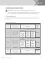
3 Wiring and Connections 21
3.1 Wiring Specifications 21
3.2 Connecting Digital Inputs and Outputs 22
3.2.1 Connecting Digital Inputs 22
3.2.2 Connecting Digital Outputs 23
3.2.3 Setting the Digital Output Jumpers 23
3.3 Connecting Common Alarm Outputs 24
3.4 RS232 Connector 24
4 Overview of Menus 25
4.1 Opening Screen Overview 26
4.2 Main Menu Overview 26
4.3 LCD Menu Overview 27
5 View Status Options 29
5.1 View Active Alarms 31
5.1.1 Active Alarms 31
5.2 View Alarm Log 32
5.2.1 Alarm Log 32
5.2.2 Backing Up the Alarm Log (Service Terminal Interface only) 33
5.3 View Event Log 33
5.3.1 Event Log 33
5.3.2 Backing Up the Event Log (Service Terminal Interface only) 34
5.4 View Input Status 35
5.4.1 Input Status 35
Vertiv | Liebert® AC4 User Manual | 3

5.5 View Output Status 36
5.5.1 Output Status 36
6 Silence Alarm & Backup Log Files (Service Terminal Interface) 37
6.1 Silence Alarm (Service Terminal Interface) 37
6.2 Back Up Log Files (Service Terminal Interface only) 37
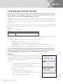
7 System and Control Options 41
7.1 Login 41
7.2 Setup System - Overview 44
7.3 Setup System - Setup Inputs 44
7.3.1 Change Label (Name of Input) 45
7.3.2 Define Input as Normally Open or Normally Closed 46
7.3.3 Define Input as Alarmable or Event 46
7.3.4 Set Up Alarmable Inputs in Latched or Unlatched Mode 47
7.3.5 Set Up Delay Time 47
7.4 Setup System - Setup Common Alarm 48
7.5 Setup System - Setup Zones 48
7.5.1 Set Up a Zone 49
7.6 Setup System - Setup Outputs 50
7.6.1 Define Output as Normally Open or Normally Closed 51
7.6.2 Define Operating or Standby Mode 51
7.6.3 Enable or Disable an Output Device in Alarm Status 51
7.6.4 Configure Output for Loss of Power (“Fail-Safe”) 52
7.7 Setup System - Setup System Info 52
7.7.1 Change Password 53
7.7.2 Set Date & Time/Automatic Daylight Saving Time 53
7.7.3 Setup Site ID 54
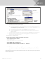
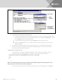
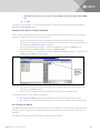
7.7.4 Backup and Upload Configuration File (Service Terminal Interface only) 54
7.7.5 Factory Defaults 57
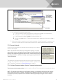
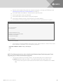
7.7.6 Perform Firmware Update (Service Terminal Interface only) 57
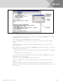
7.8 Setup Operation 60
7.8.1 Turn Automatic Sequencing On or Off 60
7.8.2 Turn Standby Testing On or Off 61
7.8.3 Specify Failed Standby Response 63
7.8.4 Specify Hold Delay Time 63
7.8.5 Specify Restart Time 64
7.9 Override Output 64
7.10 Clear Alarms & Logs 66
7.10.1 Clear Active Alarms 66
7.10.2 Clear the Alarm Log 66
7.10.3 Clear the Event Log 66
8 Specifications 67
8.1 Liebert AC4 Specifications 67
Vertiv | Liebert® AC4 User Manual | 4


Vertiv | Liebert® AC4 User Manual | 6

1 INTRODUCTION
The Liebert AC4 is ideal for coordinated control of systems with redundant equipment, such as multiple
environmental units or pumps. When the Liebert AC4 controller detects an alarm in an operating device,
the Liebert AC4 enables a standby device and controls the device in alarm as configured, either leaving
that device operating or disabling it.
The Liebert AC4 controller can also balance usage of devices by rotating units through Operating and
Standby modes according to a user-defined schedule. This helps keep redundant equipment operating
efficiently and only when needed. The Liebert AC4 can perform routine testing of standby devices and
alert personnel if a standby device fails an operating test and requires attention.
Another capability of the Liebert AC4 is monitoring the status of connected devices and keeping
personnel apprised through local alarming.
The Liebert AC4 controller can interface with anything that closes an electrical contact. To improve
process efficiency and troubleshooting, the controller tracks data in two types of logs: alarm and event.
The Liebert AC4 has a local LCD interface and an RS232 interface.
When an alarm condition arises, the Liebert AC4 displays alarm information, sounds an audible alarm,
changes the state of the common alarm relay and turns connected devices on or off according to user
configuration. See Typical Configuration on page9 for a more detailed example.
1.1 Methods of Viewing and Configuring the Liebert AC4
The Liebert AC4 features access through two interfaces that allow users to configure the unit, silence
alarms, back up logs, and perform many other functions to keep a large or small operation running
smoothly and safely.
• LCD—liquid crystal display on the front of the panel
• Service Terminal Interface—accessible via a computer connected directly to an RS232 port
These interfaces permit easy access and configuration of the Liebert AC4, allowing users to view data,
silence alarms and have full access to information stored in the controller, including logs of alarms and
events.
1.2 Data Logs
The two types of data logs—alarm history and event history—can be viewed on the LCD on the front of
the Liebert AC4 or the Service Terminal Interface. The logs may also be downloaded to a computer
through the Service Terminal Interface.
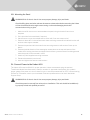
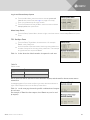
1.3 Available Alarms
The alarms available with the Liebert AC4 are:
• Discrete input alarm (for each digital input)
• Loss of power
• No standby available
• Standby device failed
• No restart available
Vertiv | Liebert® AC4 User Manual | 7

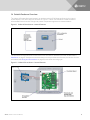
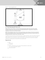
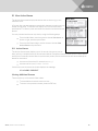
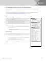
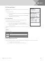
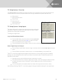
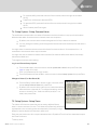
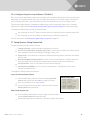
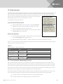
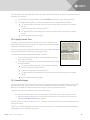
1.4 Outside Enclosure Overview
The Liebert AC4 controller board comes in an enclosure that is 2-3/4" deep and has a built-in liquid
crystal display (LCD) and a key lock, as shown in Figure 1.1 below. The enclosure is made of metal to
accommodate secure conduit fittings and protect components against environmental debris.
Figure 1.1 Liebert AC4 enclosure—external features
The enclosure must be secured to a wall, either flush-mounted or recessed in the wall, as described in
Installation on page15. Knockouts and access slots on the top and bottom allow easy connection of wires
and cables (see Wiring and Connections on page21) with either mounting type.
Figure 1.2 Liebert AC4 enclosure—internal features
Vertiv | Liebert® AC4 User Manual | 8

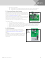
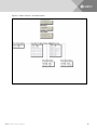
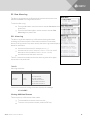
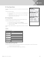
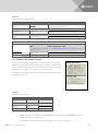
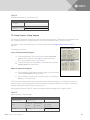
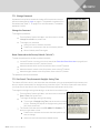
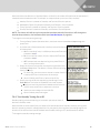
1.5 Typical Configuration
Figure 1.3 below shows an example of external devices connected to the Liebert AC4 controller board.
There may be up to four devices connected to the four digital inputs and four digital outputs. Remote
access is available through the Service Terminal Interface.
Figure 1.3 Typical Configuration
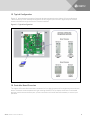
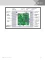
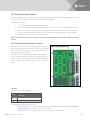
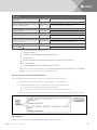
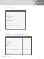
1.6 Controller Board Overview
The Liebert AC4 controller board has connectors for four digital inputs and four digital outputs, as shown
below. The board comes complete with light emitting diodes (LEDs) to display the status of connected
devices, a serial communications port, a power connection and other features necessary to control your
operation.
Vertiv | Liebert® AC4 User Manual | 9

Vertiv | Liebert® AC4 User Manual | 10

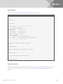
Item Description For more information, see:
A - Power On/Off switch Power switch for the controller board.
Connect Power to the Liebert AC4 on
page18
B - Audible horn Provides audible notification when an alarm occurs. N/A
C - Audible horn jumper Jumper to disable the audible horn (factory default is enabled). N/A
D - Common Alarm
connectors
The two common alarm connections are used to connect to a
secondary warning device such as a horn, light or Building
Management System (BMS). When an alarm is present, the contacts
close and the external warning device is activated/notified. The
common alarm contacts may be configured to be reset with the
Silence button/command.
Wiring and Connections on page21
Connecting Common Alarm Outputs
on page24
Setup System - Setup Common
Alarm on page48
E - Digital output status
LEDs
Each output has an LED to indicate its status: ON/OFF (energized/de-
energized).
LED Indicators below
F - Manual Override Switch
(outputs)
Placing the switch in the ON position will turn ON, or energize, all four
outputs simultaneously. This switch removes all automatic output
control from the Liebert AC4.
Override Output on page64
G - Digital output
connectors
Each of the four output connections is a two-state point: ON/OFF
(energized/de-energized).
An example of a field digital output is a Liebert Environmental unit’s
remote shutdown input.
Wiring and Connections on page21
Connecting Digital Outputs on
page23
View Output Status on page36
Setup System - Setup Outputs on
page50
H - Status LEDs Indicates the operational status of the controller board. LED Indicators below
I - Digital output loss-of-
power jumper
One of four output jumpers. Each digital output has a jumper to set the
fail-safe position of the output point when power fails. The OFF position
makes the contact Normally Open (factory default). The ON position
makes the contact Normally Closed.
Note: The jumper position has no effect on the contact when the
Liebert AC4 has power.
Setting the Digital Output Jumpers on
page23
Configure Output for Loss of Power
(“Fail-Safe”) on page52
J - Digital input connectors
Each of the four input connections is a two-state point: ON/OFF
(energized/de-energized).
An example of a field digital input is a Liebert Environmental unit’s
common alarm relay output.
Wiring and Connections on page21
Connecting Digital Inputs on page22
View Input Status on page35
Setup System - Setup Inputs on
page44
K - Digital input status LEDs
Each input has an LED to indicate its status: ON/OFF (energized/de-
energized).
LED Indicators below
L - Serial interface
connector (RS232/EIA574)
Connection for laptop or video terminal. Used for configuration and
monitoring using the Service Terminal Interface. Requires a null
modem cable for connectivity
(P/N 201258P1).
RS232 Connector on page24
Connecting to the Service Terminal
Interface on page70
M - DIP switch 1 DIP switch used for resetting password to default. Change Password on page53
N - LCD connector Connection for the LCD on the enclosure door. N/A
O - LCD contrast
adjustment
Adjustment contrast for the LCD on the enclosure door. N/A
P - 24VAC power connector Power connection for the controller. Requires 24VAC.
Connect Power to the Liebert AC4 on
page18
Table 1.1
Controller board components
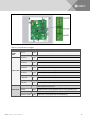
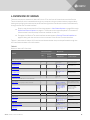
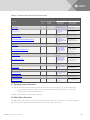
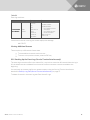
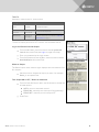
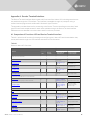
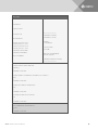
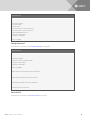
1.7 LED Indicators
The Liebert AC4 controller board has LED indicators that show the status of inputs, outputs and the
common alarm
Vertiv | Liebert® AC4 User Manual | 11

LED Type LED Color Description
EIA422
LEDs
422 TX Green Liebert AC4 is transmitting information over the EIA422 port
422 RX Green Liebert AC4 is receiving information over the EIA422 port
Output LEDs
OUTPUT1 Green Not used
OUTPUT2 Green Not used
OUTPUT3 Green Not used
OUTPUT4 Green Not used
OUTPUT5 Green Indicates output 1 is ON or energized
OUTPUT6 Green Indicates output 2 is ON or energized
OUTPUT7 Green Indicates output 3 is ON or energized
OUTPUT8 Green Indicates output 4 is ON or energized
CTRLLOCK N/A Not used
SENLOCK N/A Not used
CMN ALR Green Indicates output is ON or energized
Status LEDs
MOP Green
Indicates the microprocessor is operating properly (MOP)—must be on
before Liebert AC4 will function
FPROG Green Indicates firmware is being upgraded—lights up during upgrade process
574 TX or 232 TX Green Liebert AC4 is transmitting information via the RS232 port
574 RX or 232 RX Green Liebert AC4 is receiving information via the RS232 port
Table 1.2 LED indicators summary
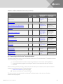
Vertiv | Liebert® AC4 User Manual | 12

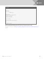
LED Type LED Color Description
485 RX Green Not used
485 TX Green Not used
Input LEDs
INPUT1 Red Not used
INPUT2 Red Not used
INPUT3 Red Not used
INPUT4 Red Not used
INPUT5 Red Indicates input 1 is ON or energized
INPUT6 Red Indicates input 2 is ON or energized
INPUT7 Red Indicates input 3 is ON or energized
INPUT8 Red Indicates input 4 is ON or energized
Table 1.2 LED indicators summary (continued)
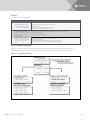
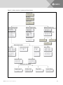
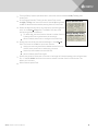
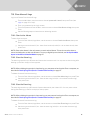
1.8 Typical Sequence
Figure 1.4 on the next page shows a typical sequence of how the Liebert AC4 functions after detecting a
change in a monitored device. Many responses depend on configuration settings. This example shows
what happens when a digital input changes state—assuming the input is defined as alarmable—and
when the condition returns to normal.
Vertiv | Liebert® AC4 User Manual | 13

Figure 1.4 Example of typical sequence
Vertiv | Liebert® AC4 User Manual | 14

2 INSTALLATION
2.1 Installation Considerations
The Liebert AC4 must be installed indoors and may be mounted on the surface of a wall or flush-mounted,
depending on the user’s application, the location of equipment to be connected and the type of wall the
unit will be mounted on.
The Liebert AC4 should be mounted where it can be easily accessed. On-site personnel would access the
unit through the LCD on its front cover or the service terminal connected to the RS232 port.
In addition to the communications connections, the site also must have electrical service and must permit
connecting the unit’s four digital inputs and four digital outputs.
The wall material must be capable of supporting the weight of the Liebert AC4: see Specifications on
page67.
NOTE: This equipment has been tested and found to comply with the limits for a Class A digital device,
pursuant to part 15 of the FCC rules. These limits are designed to provide reasonable protection
against harmful interference when the equipment is operated in a commercial environment. This
equipment generates, uses, and can radiate radio frequency energy and, if not installed and used in
accordance with the instruction manual, may cause harmful interference to radio communications.
Operation of this equipment in a residential area is likely to cause harmful interference in which case
the user will be required to correct the interference at his own expense.
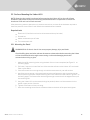
2.1.1 Unpacking and Preliminary Inspection
• Before unpacking the Liebert AC4, inspect the shipping carton for damage or signs of
mishandling, such as gashes or holes in the carton or severely flattened corners.
• Open the shipping crates carefully. Use care to avoid puncturing the container with sharp
objects that might damage the contents.
• Inspect the Liebert AC4 and all included components for damage.
• If any damage from shipping or mishandling is observed, immediately file a damage claim with
the shipping agency and forward a copy to:
Liebert Corporation
1050 Dearborn Drive
P.O. Box 29186
Columbus, OH 43229
Packing Contents
Standard Components
Liebert AC4 controller board in enclosure
User Manual
Keys (2) to panel door lock
RS232 Configuration Cable
Table 2.1 Packing manifest
Vertiv | Liebert® AC4 User Manual | 15

2.2 Surface-Mounting the Liebert AC4
NOTE: Removing the conduit knockouts before mounting the Liebert AC4 on the wall will ease
installation and prevent strain on the mounting hardware and wall. It is imperative to remove the
knockouts if the unit is to be flush-mounted.
After determining where to place the unit, check to ensure that you have all the hardware required to
install the panel on the surface of a wall. Obtain the needed tools and material.
Required tools
• Electric drill (if surface is too hard to drive screws without pilot holes)
• Screwdriver
• Marker to denote layout of holes
• Four screws, each #10
2.2.1 Mounting the Panel
WARNING! Risk of electric shock. Can cause property damage, injury and death.
Check building plans and other relevant documents to determine whether mounting the Liebert
AC4 at the selected location might cause cutting or otherwise damaging electrical or
communication wiring or pipes.
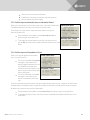
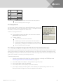
1. Mark the wall for mounting holes, using the back of the unit as a template (see Figure 2.1 on
the facing page).
2. Drill holes, if required, to install the four #10 screws that will secure the Liebert AC4 to the wall.
Clean up the debris.
3. If the wall material is not strong enough to hold the screws securely, use wall anchors.
4. Install the top two screws—the screw heads must be small enough to slip through the larger,
bottom portion of the pear-shaped mounting slot in the Liebert AC4 (see inset in Figure 2.1 on
the facing page). The screws must also be large enough to extend over the edges of the top of
the mounting slot.
5. Hang the Liebert AC4 on the screws, letting the panel slip down until the screws are in the
smaller, upper portion of the slot.
6. Tighten the screws until they are snug.
7. Insert the remaining two screws in the bottom holes on the back of the panel and tighten.
Vertiv | Liebert® AC4 User Manual | 16

Figure 2.1 Mounting dimensions
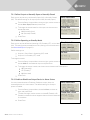
2.3 Flush-Mounting the Liebert AC4
NOTE: Removing the conduit knockouts before mounting the Liebert AC4 on the wall will ease
installation and prevent strain on the mounting hardware and wall. It is imperative to remove the
knockouts if the unit is to be flush-mounted.
NOTE: The rectangular access doors on the top and bottom of the Liebert AC4 must be reversed so
they slide the opposite direction. Leaving the doors as shipped from the factory prevents them from
being opened when the panel is flush mounted in a wall.
The Liebert AC4 may be flush mounted according to company practices—either with screws through the
sides of the panel into wall supports or with hanging hardware that attaches to the back of the panel.
After determining how and where to place the unit, check to ensure that you have all the hardware
required to install the panel in the wall. Obtain the needed tools.
Required tools
• Saw
• Electric drill
• Screwdriver
• Marker to denote layout of the hole to accommodate the Liebert AC4
• Trim ring and associated hardware
• Mounting hardware
Vertiv | Liebert® AC4 User Manual | 17

2.3.1 Mounting the Panel
WARNING! Risk of electric shock. Can cause property damage, injury and death.
Check building plans and other relevant documents to determine whether mounting the Liebert
AC4 at the selected location might cause cutting or otherwise damaging electrical or
communication wiring or pipes.
1. Mark the wall for the cutout to accommodate the panel, using the back of the unit as a
template.
2. Drill a pilot hole for the saw blade, if required.
3. Use the saw to cut out the marked section of the wall (if not new construction).
4. Rest the Liebert AC4 in the wall and mark where mounting screws will be inserted into the wall
studs or other support member.
5. Remove the panel and drill the holes for the mounting screws or wall anchors. Clean up the
debris.
6. Reverse the slide direction of the rectangular access doors on the top and bottom of the
Liebert AC4. Leaving the doors as shipped from the factory prevents them from being opened
when the panel is flush mounted in a wall.
7. Attach any field-supplied mounting hardware.
8. Reinsert the assembly into the wall.
9. Insert and tighten the screws or wall anchors.
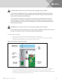
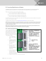
2.4 Connect Power to the Liebert AC4
The Liebert AC4 requires 24VAC for proper operation. Liebert recommends using the optional
Transformer Module manufactured by Liebert or another UL-approved class 2 power unit to obtain
proper voltage. If the power unit is not a class 2 circuit, it must be protected with an IEC 5x20mm time lag
2A fuse. For information, consult your local dealer, Emerson representative or the Vertiv Worldwide
Support Group.
WARNING! Risk of electric shock. Can cause property damage, injury and death.
Check that power is removed from wires prior to installation. This unit should be installed only
by properly trained and qualified personnel.
Vertiv | Liebert® AC4 User Manual | 18

CAUTION: Risk of electric shock. Can cause property damage, injury and death.
The Liebert AC4 is designed for use on properly grounded (earthed) 24VACpower, 50Hz or
60Hz. The ground wire for the power lead must be wired to the earth ground terminal (stud
located next to the 24VAC terminal block).
This equipment is intended to be installed by a qualified and certified electrician who must
review and approve customer supplied wiring and circuit breakers, verify correct input and
grounded (earthed) connections to ensure compliance with technical standards and national
and local electrical codes.
WARNING! Risk of electric shock. Can cause property damage, injury and death.
Be sure that the Power On/Off switch is set to OFF before installing any wiring to this unit. The
switch is in the top left corner of the unit, just below the battery pack.
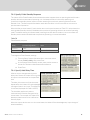
To connect electrical power:
1. Run conduit and electrical wiring from building to the Liebert AC4.
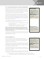
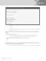
2. Use copper wires only; proper wiring to use for power is 18-22 AWG stranded and shielded
(18AWG is recommended—see 3 on page21). Strip wires 1/2".
Figure 2.2 Electrical connections to panel
3. Secure the incoming electrical service wires to the Liebert AC4’s 24VAC input by sliding the
wires into TB7, the 24VAC input terminal block. There is no polarity requirement when
connecting to TB7. The ground wire must be connected to the earth ground terminal located
on the side of the panel (see Figure 2.2 above).
Vertiv | Liebert® AC4 User Manual | 19

Vertiv | Liebert® AC4 User Manual | 20
This page intentionally left blank.
Page is loading ...
Page is loading ...
Page is loading ...
Page is loading ...
Page is loading ...
Page is loading ...
Page is loading ...
Page is loading ...
Page is loading ...
Page is loading ...
Page is loading ...
Page is loading ...
Page is loading ...
Page is loading ...
Page is loading ...
Page is loading ...
Page is loading ...
Page is loading ...
Page is loading ...
Page is loading ...
Page is loading ...
Page is loading ...
Page is loading ...
Page is loading ...
Page is loading ...
Page is loading ...
Page is loading ...
Page is loading ...
Page is loading ...
Page is loading ...
Page is loading ...
Page is loading ...
Page is loading ...
Page is loading ...
Page is loading ...
Page is loading ...
Page is loading ...
Page is loading ...
Page is loading ...
Page is loading ...
Page is loading ...
Page is loading ...
Page is loading ...
Page is loading ...
Page is loading ...
Page is loading ...
Page is loading ...
Page is loading ...
Page is loading ...
Page is loading ...
Page is loading ...
Page is loading ...
Page is loading ...
Page is loading ...
Page is loading ...
Page is loading ...
Page is loading ...
Page is loading ...
Page is loading ...
Page is loading ...
Page is loading ...
Page is loading ...
Page is loading ...
Page is loading ...
Page is loading ...
Page is loading ...
Page is loading ...
Page is loading ...
Page is loading ...
Page is loading ...
Page is loading ...
Page is loading ...
Page is loading ...
Page is loading ...
Page is loading ...
Page is loading ...
Page is loading ...
Page is loading ...
Page is loading ...
Page is loading ...
-
 1
1
-
 2
2
-
 3
3
-
 4
4
-
 5
5
-
 6
6
-
 7
7
-
 8
8
-
 9
9
-
 10
10
-
 11
11
-
 12
12
-
 13
13
-
 14
14
-
 15
15
-
 16
16
-
 17
17
-
 18
18
-
 19
19
-
 20
20
-
 21
21
-
 22
22
-
 23
23
-
 24
24
-
 25
25
-
 26
26
-
 27
27
-
 28
28
-
 29
29
-
 30
30
-
 31
31
-
 32
32
-
 33
33
-
 34
34
-
 35
35
-
 36
36
-
 37
37
-
 38
38
-
 39
39
-
 40
40
-
 41
41
-
 42
42
-
 43
43
-
 44
44
-
 45
45
-
 46
46
-
 47
47
-
 48
48
-
 49
49
-
 50
50
-
 51
51
-
 52
52
-
 53
53
-
 54
54
-
 55
55
-
 56
56
-
 57
57
-
 58
58
-
 59
59
-
 60
60
-
 61
61
-
 62
62
-
 63
63
-
 64
64
-
 65
65
-
 66
66
-
 67
67
-
 68
68
-
 69
69
-
 70
70
-
 71
71
-
 72
72
-
 73
73
-
 74
74
-
 75
75
-
 76
76
-
 77
77
-
 78
78
-
 79
79
-
 80
80
-
 81
81
-
 82
82
-
 83
83
-
 84
84
-
 85
85
-
 86
86
-
 87
87
-
 88
88
-
 89
89
-
 90
90
-
 91
91
-
 92
92
-
 93
93
-
 94
94
-
 95
95
-
 96
96
-
 97
97
-
 98
98
-
 99
99
-
 100
100


Liebert Liebert® AC4 User manual
- Type
- User manual
- This manual is also suitable for
Ask a question and I''ll find the answer in the document
Finding information in a document is now easier with AI
Related papers
-
Liebert AC4 User manual
-
-
-
-
-
-
-
-
-
Other documents
-
Ecler How to Reset MIMO88 to Factory Defaults User manual
-
Emerson AC4 User manual
-
Vertiv Liebert® DCDactive Fan Module User manual
-
-
-
-
-
Vertiv Liebert® DSE 250-265 kW Thermal Management System User manual
-
Vertiv Liebert® iCOM™ User manual
-