Page is loading ...

1
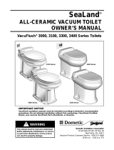
IMPORTANT NOTICE
VacuFlush sanitation systems
must be installed according to
Dometic’s recommended procedures.
Do not attempt installation without
rst contacting a SeaLand
Certied Dealer, your nearest
Parts Distributor (see page 19),
or Dometic.
Dometic Sanitation Corporation
13128 State Rt 226, PO Box 38
Big Prairie, OH 44611
SeaLand Product Customer Service: 1-800-321-9886
(8:00 a.m. - 5:00 p.m. ET)
This manual must be read and under-
stood before installation, adjustment,
service, or maintenance is performed.
Modication of this product can result
in property damage.
WARNING
!
3606 3609
SeaLand
®
VACUUM TOILET
OWNER’S MANUAL
VacuFlush
®
3600 Series All-Ceramic Toilets

2
TABLE OF CONTENTS
The model identication label is located under the toilet
seat. It will show the model number and serial number.
TOILET MODEL IDENTIFICATION
DOMETIC CORPORATION
P.O. BOX 38, 13128 STATE RT 226 (800) 321-9886
BIG PRAIRIE, OH 44611 USA
MODEL NO. 000
SERIAL NUMBER
000000
WARNING – ELECTRICAL SYSTEM.
Turn off electrical power before servicing.
WARNING – MOTOR STARTS AUTOMATICALLY.
Turn off electrical power before servicing.
Read and understand the complete contents of this manual before operating or servicing the sanitation
system. Failure to follow any precautions may result in damage to the sanitation system.
CAUTION –
System may contain vacuum after shut-down.
Toilet Model Identication . . . . . . . . . . . . . . . . . 2
Important Information Before Operation . . . . . . 3
Toilet Control Switches . . . . . . . . . . . . . . . . . . . 3
Operating Instructions . . . . . . . . . . . . . . . . . . . . 4
Proper Toilet Bowl Cleaning . . . . . . . . . . . . . . . 5
Winterizing . . . . . . . . . . . . . . . . . . . . . . . . . . . . 5
Flush Operation Timing Chart . . . . . . . . . . . . . . 5
Maintenance Schedule . . . . . . . . . . . . . . . . . . . 6
On-Board Spare Parts . . . . . . . . . . . . . . . . . . . . 6
Sanitation System Components . . . . . . . . . 6 – 8
Ordering Parts . . . . . . . . . . . . . . . . . . . . . . . . . . 8
Deodorants and Special Tissue . . . . . . . . . . . . 9
Marine Sanitation Regulations . . . . . . . . . . . . . 9
Flush Mechanism Components . . . . . . . . . . . . 10
Manual Flush Override . . . . . . . . . . . . . . . . . . .11
Toilet System Electrical Specications . . . . . . .11
Troubleshooting . . . . . . . . . . . . . . . . . . . . 12 – 15
System Wiring Diagrams . . . . . . . . . . . . . 16 – 18
Customer Service . . . . . . . . . . . . . . . . . . . . . . 19
Warranty . . . . . . . . . . . . . . . . . . . . . . . . . . . . . 20
Dometic, SeaLand, VacuFlush and Flush and Forget are registered trademarks
of Dometic Corporation.

3
IMPORTANT INFORMATION BEFORE OPERATION
1. Fill freshwater tank and add deodorant to holding tank through toilet bowl.
2. Make sure all guests understand the operation of the toilet system and the ushing instruction label is easy for
guests to read. This label is located under the seat, and is easily read when the seat is raised.
3. Remember the vacuum pump starts automatically. Shut off the toilet system before servicing and do not leave the
boat with toilet system breaker on.
4.
Never use drain openers, alcohol, solvents, etc. in the system.
5. If the system does not function properly, refer to the Troubleshooting section of this manual and repair as
necessary. If problem persists, contact your local SeaLand dealer or see the Customer Service section of this
manual.
1. To add water to the toilet before
using (if necessary), press “Add
Water” button until desired water
level is reached.
2. To flush toilet, press “Flush”
button. Water will ow into bowl
for two seconds, then ush ball
will open. Toilet will not flush
again until “OK to Flush” light
is on.
3. Do not dispose of sanitary
napkins or other non-dissolving
items in toilet, such as facial
tissue or paper towels. These
items can cause plugging of the
sanitation system.
FLUSH and FORGET
®
OPERATION
TOILET CONTROL SWITCHES
CONTROL MODULE ACCESS COVER
CONTROL SWITCHES
ADD WATE R FLUSH
Water Level and Mode control switches are located under the control module access cover which is under the toilet
seat. Remove the cover by unlatching the cover tab behind the toilet seat (Fig. A), then, with the toilet seat raised
up and tilted forward slightly, lift up the cover (Fig. B). The control switch label (see below) is found under the seat
behind the access cover.
Fig. A
Fig. B

4
OPERATING INSTRUCTIONS
1. Adding More Water To Toilet Bowl
Press the “Add Water” switch until the desired water level is attained. To prevent overowing the toilet, a timer
limits the amount of water that can be added.
2. Flushing The Toilet
When the ush panel’s green “OK to Flush” light is on, and the red “Do Not Flush” light is off, press the “Flush”
switch down for a moment then release it. Holding the switch down will not prolong the ush cycle nor start a new
ush cycle. The switch must be allowed to return to the “off” position and the vacuum must be allowed to recharge
before another ush cycle can be initiated. A full holding tank will also prevent the toilet from ushing.
3. Selecting Automatic Water Rell Levels:
The Water Level switch is located under the control module access cover on the left side of the board. There are
three water rell levels available. The microprocessor-controlled water valve will rell the toilet bowl according
to your water level selection. To reinstall the access cover. set the cover over the control module and press the
push-pins into the grommets located in the toilet seat mounting bracket.
LOW Level
Use this setting to conserve water. This position may be desirable to reduce the chance of water splashing out
of the bowl during rough travel conditions. If more water is needed for ushing, press the “Add Water” ush
switch. Water ow will stop after nine seconds to prevent overow.
MID Level
Use this position to keep the toilet bowl clean, especially when family and friends may be using the toilet. If
more water is still needed for ushing, pressing the “Add Water” ush switch will provide up to six seconds of
additional water rell time.
HIGH Level
Use this position if the MID level does not provide a clean toilet bowl. This position is not recommended while
underway. If more water is still desirable for ushing, pressing the “Add Water” ush switch will provide up to
three seconds of additional water rell time.
4. Mode Switch
The Mode switch is located on the right side of the control module. It lets you switch between three function
settings:
NORMAL
Use this setting for ushing the toilet.
SERVICE
Use this position for cleaning the toilet bowl and ush ball seal. The ush ball will open automatically and remain
open in this position. Pressing the “Add Water” ush switch provides water. You may want to turn off power
to the vacuum generator or vacuum pump when in the SERVICE position for long periods of time to prevent
unnecessary vacuum pump operation.
Note: The control module allows 15 seconds of water ow for cleaning. If more water is required, return
the switch to the NORMAL position then back to the SERVICE position.
MANUAL OVERRIDE
Use this position to ush the toilet in the event of power or battery failure. The OVERRIDE position releases the
ush valve motor brake, and allows manual opening of the ush ball via the access hole in the left side of the
vitreous china base. Remove the large plug in the left side of the toilet, insert a large, at-bladed screwdriver
into the slot of the motor shaft, and turn counterclockwise to open the ush ball.
Return the switch to the SERVICE position, then to the NORMAL position to reset the control circuit in the
toilet.

5
WINTERIZING
At the end of each boating season, the VacuFlush toilet system must be winterized for storage. The following procedure
should be used:
1. Pump out holding tank.
2. Thoroughly ush system with fresh water.
3. Drain freshwater tank.
4. Add freshwater antifreeze to freshwater tank.
5. Flush freshwater antifreeze and water mixture through toilet
and into the waste holding tank. Each installation is different
so amounts may vary. User discretion is required to assure
adequate protection.
6. Turn off electrical power.
CAUTION: The use of freshwater antifreeze that contains alcohol will result in damage to your sanitation
system. Only use propylene glycol freshwater antifreeze that does not contain alcohol.
PROPER TOILET BOWL CLEANING
“Add Water” Time Limits
Flush and Forget
®
Cycle Time
AUTOMATIC FLUSH OPERATION TIMING CHART
“Add Water” Time In Seconds
5 1284
1
7
11
6 13 159 143
10
2 16
0 2.5
Water Valve
Low Position
High Position
Service Position
Mid Position
Flush Cycle In Seconds
16
5 1284
1
7
11
6 13 159 143
10
2
0 2.5
Water Valve
Flush Valve
Low Rell
Mid Rell
High Rell
Begin Opening for 0.1 sec.
Wait for 0.2 sec.
Continue Opening
Held Open
Closing Time
Additional “Add Water” Time Allowance
For stubborn stains, use SeaLand
®
Toilet Bowl Cleaner (Fig. C). It’s manufac-
tured especially for use with SeaLand toilets. In certain locations where water
is hard, a build-up of lime may dull the toilet bowl nish. Restore the shine
with this SeaLand cleaner. If you cannot nd it in your area, contact Dometic
for your nearest dealer. If the cleaner is not available, you can also use most
non-abrasive bathroom and toilet bowl cleaners (Bar Keeper's Friend
®
spray
cleaner, Clorox
®
toilet bowl cleaner, SaniFlush
®
toilet bowl cleaner, etc.).
Please follow label instructions.
To avoid damaging the Teon
®
-coated seal, DO NOT USE:
– abrasives (Comet
®
, Soft Scrub
®
cleansers etc.)
– caustic chemicals (Drano
®
clog remover, etc.)
– lubricants and cleaners containing alcohols or petroleum distillates
(Pam
®
cooking spray, Pine-Sol
®
cleaner, WD-40
®
lubricant, etc.).
Fig. C
® Bar Keepers Friend is a registered trademark of SerVaas Laboratories Inc.
® Clorox, Pine-Sol and Soft Scrub are registered trademarks of The Clorox Co.
® Comet is a registered trademark of Prestige Brands International.
® Drano is a registered trademark of S.C. Johnson & Son Inc.
® Pam is a registered trademark of ConAgra Foods.
® Sani-Flush is a registered trademark of Reckitt Benckiser Inc.
® Teon is a registered trademark of DuPont Co.
® WD-40 is a registered trademark of WD-40 Company.

6
SANITATION SYSTEM COMPONENTS
*
*
*
*
* Optional SeaLand components
MAINTENANCE SCHEDULE
Maintenance intervals and normal parts replacement vary widely depending on numerous factors such as frequency
of system use, quality of ushing water, etc. The following chart is intended strictly as a general guide in keeping the
sanitation system 100% ready for any conditions of use.
Maintenance Procedure
Recommended
Date of Service
Parts Required
Toilet ush ball seal cleaning
Tighten toilet seat mounting
hardware
Monthly
Monthly (or as needed)
SeaLand Toilet Bowl Cleaner
N/A
ROUTINE MAINTENANCE
Replace duckbill valves in vacu-
um pump or vacuum generator
Replace ush ball seal and ush
ball (if needed)
Every three years
Every three years
Duckbill Valve Kit
Flush Ball Seal Kit
Flush Ball
MAJOR SYSTEM MAINTENANCE
ON-BOARD SPARE PARTS
It is recommended that the following parts be kept on board at all times:
Description
Part Number
Quantity Where Used
Flush Ball Seal
Flush Ball
Water Valve
Vacuum Breaker Kit
Vacuum Switch Kit
1.5-inch Duckbill Valve Kit
(2 ea. per kit)
see parts list
see parts list
see parts list
see parts list
see parts list
see parts list
1
1
1
1
1
1
3600 Series Toilet
Vacuum Generating System

7
SANITATION SYSTEM COMPONENTS (cont’d)
Vacuum Toilet: The 3600 series vacuum toilet with Flush
and Forget
®
technology operates in a way different from
other marine toilets. Vacuum systems use a small amount
of water (a little more than a pint or .5 liter) per ush in
addition to a simple vacuum. The toilet is connected to a
pressurized freshwater system. Fresh water is the key to an
odor-free bathroom compartment. VacuFlush toilets are
equipped with an integral vacuum breaker which prevents
the possible contamination of the freshwater supply.
Flush/Add Water Switches: Wall-mounted push-button
switches provide electronic operation of ushing and adding
water to the toilet bowl. Models include two-light vacuum
status panel indicating the toilet is “OK to Flush” or “Do Not
Flush”. Models vary.
Vacuum Generator: VacuFlush vacuum generators
combine the vacuum tank and vacuum pump in one unit.
It greatly reduces installation time and eliminates the hose
run between the tank and pump. Our vacuum generators
are available in standard or low-prole congurations,
depending on installation requirements.
Vacuum Tank: The vacuum tank stores vacuum energy.
System vacuum level is monitored by a vacuum switch
located on the vacuum tank. When this switch senses
a drop in vacuum in the system, it automatically signals
the pump to energize and bring the vacuum to operating
level. This process is normally completed in less than one
minute.
Vacuum Pump: The vacuum pump is an electric,
straight-through bellows type. It is manufactured of long-
lasting polypropylene and draws only 4 to 6 amps of current
at 12 VDC. This unique pump design is both an efcient air
and liquid pump that handles solids without a problem. It
has two duckbill valves on each side of the pump chamber
to maintain vacuum and prevent backow of waste.
TankWatch
®
Level Indicator (optional): The TankWatch
unit utilizes micro-oat switches which activate an indicator
panel. The inspection cap in the holding tank contains the
micro-oat switch units. The adjustable probe assemblies
are exible polybutylene tubing and are designed to ex
when tank contents move.
Holding Tanks (optional): SeaLand holding tanks are
made of super-strong, 3/8” (10mm) thick polyethylene
— 50% thicker than most other holding tanks. Each unit
has a solid, one-piece construction with no seams for un-
matched durability. A deodorant additive is required to keep
the holding tank odor-free. See Deodorants and Special
Tissue section for further information.
TankWatch
Panel and
Probes
Vacuum Generators
VacuFlush
®
3600 Series
Toilet
Holding Tanks
Vacuum Tank and
Vacuum Pump
Flush/Add Water Switches
Vimar Gewiss

8
*Nozzle
*Not included.
*Deck Fitting
SANITATION SYSTEM COMPONENTS (cont’d)
In-Line Vent Filter (optional): The SaniGard
TM
vent lter
has special odor-removing lter materials to help keep your
boat smelling clean and pleasant. Heavier-than-air mal-
odors accumulate in the holding tank. This vent lter has a
special type of activated lter media to remove these odors
before they offend. Each cartridge is good for an entire sea-
son, and is easily replaced for a fresh start. Replacement
cartridges are available (see Customer Service).
Vacuum Generator Shut-down Relay (optional): This
relay automatically shuts down power to the vacuum toilet
system to prevent overlling of the holding tank. Item num-
ber 310289 (12 VDC) or 310290 (24 VDC).
Vacuum Tester (optional): Dometic has developed a
simple tool to assist in identifying the location of vacuum
leaks. The vacuum tester consists of a vacuum gauge and a
cone-shaped plug. Inserting the plug in the inlet of the vac-
uum tank or vacuum generator isolates the toilet from the
system. In this way a troublesome vacuum leak can easily
be located in either system. Item number 530002.
SaniPump™ Discharge Pump (optional): The T-series
SaniPump discharge pump can run dry without harm and
draws just 6 amps at 12 VDC. Delivers ow rate of just
over 3.0 gallons per minute (11.4 liters per minute). Emp-
tying an onboard tank usually takes 4 to 6 minutes. The
discharge pump is connected to a through-hull tting. Check
Marine Sanitation Regulations for areas where discharge
is allowed.
NozAll
TM
Pumpout Adapter (optional): The NozAll
pumpout adapter provides an airtight seal between your
boat’s deck waste tting and the pumpout station nozzle.
Just screw the NozAll adapter into your deck tting, and be
assured of an airtight connection for pumping out holding
tanks. Each item contains a nylon NozAll adapter, gasket
and vinyl cap. Item number 343502 (1-1/2”–11.5 tpi),
343503 (1-1/4”–11.5 tpi), or 343504 (1-1/4”–16 tpi).
Vacuum Tester
SaniPump
Waste
Discharge
Pump
Vent Filter
ORDERING PARTS
Dometic is ready to assist you in the event service is required. Before calling, please have the following information
available. Your cooperation in having this information ready is appreciated and allows us to better meet your needs.
Please refer to the Parts Distributor list in the Customer Service section.
1. Toilet Model Number
2. Serial Number
3. Part Number, Description and Quantity (see Parts List.)
NozAll™ Adapter

9
MARINE SANITATION REGULATIONS
All boats with xed toilets in U.S. waters and in the waters of some other countries are required to be equipped with an operable
marine sanitation device (MSD). The VacuFlush sanitation system is a holding tank or Type III system as dened by the U.S.
Coast Guard.
Type III systems are designed to permit operation of the toilet without the direct discharge of untreated waste after every ush.
This means onboard toilet facilities can be used when the boat is near swimmers, beaches or shellsh beds.
Type III systems can be discharged at marina dockside pump-out stations or, if in coastal waters, a minimum of three miles off-
shore. Overboard discharge capability must remain secured while within the three-mile limit. The overboard discharge
pump is activated by a keyed switch located in the toilet compartment. This key should be removed at all times except when
discharge pump is operating.
Federal legislation provides grants to private marinas to install dockside pumps especially in coastal water. It is estimated that
over 3,500 pump-out stations, in total, will be added due to this legislation.
Sewage from any source should not be discharged directly into our waters. If you are interested in learning more about this
issue, please contact Dometic at the phone number or address listed on the back page of this manual.
DEODORANTS AND SPECIAL TISSUE
Your VacuFlush toilet and sanitation system require the regular addition of a deodorant product to reduce malodors and
to help break down holding tank contents. Several factors should be considered in selecting a deodorant product.
Liquid or Dry: Liquid products obviously work more quickly by readily going into solution. Granulated powder
formulations, on the other hand, have the advantage of requiring less storage space and are less likely to leak if the
package is inadvertently damaged.
Formaldehyde versus Non-Formaldehyde: Dometic manufactures both types of deodorants. Generally speak-
ing, formaldehyde formulas control odor very effectively at all temperatures and with all degrees of water hardness.
SeaLand
®
Environment-Friendly brand, which is formaldehyde free, is similarly effective.
How Much Deodorant and How to Add It: The deodorant is added directly into the toilet bowl, then ushed into
the holding tank. Follow bottle or package instructions. Conditions of extremely warm weather, longer waste hold-
ing time and larger tank capacities may require more deodorant treatment. Also, to maintain optimum efciency in
odor control, the waste holding tank should be cleaned thoroughly at least once or more each season, depending
on use.
Why Not Use Household Toilet Paper in Your SeaLand Toilet? Household tissues often contain adhesives which
bond together the paper bers from which the tissue is made. The adhesives prevent the tissue from breaking apart,
and their use in “ultra-low ow” systems can cause system clogging. SeaLand tissue is especially designed for use
in low water toilet systems. Its rapid dissolving properties minimize the amount of residual paper in the holding tank
and allow deodorizers to work more efciently.
SeaLand versus Other Brands: SeaLand constantly strives to provide our system owners with effective products
that have minimal environmental impact and good value. Many deodorant products do not measure up to our
standards of performance and value.
SeaLand
®
Granulated
Deodorant
Six 2-oz. pouches
Part No.
379626002
SeaLand
®
Liquid
Deodorant
Two 8-oz. bottles
Part No.
379224008
SeaLand
®
Cleaner
16-oz. bottle
Part No.
379314016
SeaLand
®
Liquid
Deodorant -
Environment Friendly
32-oz. bottle
Part No.
379114032
SeaLand
®
Rapid-Dissolving
Toilet Tissue
Four 400-sheet rolls
Part No. 379441204

10
FLUSH MECHANISM COMPONENTS
1. To access ush
mechanism compo-
nents, remove decora-
tive caps and unscrew
fasteners that hold china
toilet to oor.
2. Remove PC board
access cover and
set it aside. Unscrew
small screws next to
control switches and
lift control module.
Use small screwdriver
to disconnect power
cable and vacuum
control cable from
control module.
Do not disconnect
base assembly cable.
3. Lift china toilet
straight up and set it
down close to front
of mounting adapter.
Turn off water to toilet
and disconnect ex-
ible water line at rear
of base assembly. The
toilet is completely
disconnected.
Base Assembly
Cable
BASE ASSEMBLY COMPONENTS
(under china toilet)
Water Valve
Flush Ball
Closed Limit
Switch
Motor
Drive Arm
Rotor Arm
Flush Valve
Motor
Flexible Water Supply Hose
Open Limit
Switch
Discharge
Adapter
Mode
Switch
Water
Level Switch
Power
Cable
CONTROL MODULE
Input for
Base Assembly
Cable
Input
for
Flush
Switch
Cable
Input
for
Vacuum
Control
Cable

11
MANUAL FLUSH OVERRIDE
In the event of an electrical failure, the ush ball can be manually operated to clear the bowl. We recommend using
a long-neck screwdriver or 7/16-in. socket for the operation shown below. NEVER PRY OPEN THE FLUSH BALL
FROM INSIDE THE TOILET BOWL. Damage to the ush ball and bowl seals may result.
2. Locate hole on left side
of china toilet. This
allows access to the
ush valve motor drive
arm.
3. Insert screwdriver or
7/16-in. socket through
access hole and onto
hex head.
4. Turn screwdriver or sock-
et counter-clockwise.
This will open ush ball
and allow bowl contents
to clear. After bowl is
clear, turn screwdriver or
socket clockwise to return ush ball to original position.
1. Remove PC board
access cover. Place
Mode Switch in the
“Manual Override” posi-
tion. This disconnects
ush valve motor brake
from electrical circuit.
NOTES:
Water will not enter the toilet bowl during manual ush
operation.
Place Mode Switch in the “Normal” position before
returning to automatic operation.
Manual Override
position
TOILET SYSTEM ELECTRICAL SPECIFICATIONS
12VDC 24VDC
Maximum standby current (amps): .080 .080
Maximum operating current (amps): 6.5 2.5
Flush motor locked rotor current (amps): 14.5 7.25
Maximum voltage 15 30
Minimum voltage: 10 20
Input power wire size 14 ga. 14 ga.
All other wires size: 18 ga. 18 ga.
Fuse size (amps) 8 4
NOTES: Standby current includes ush panel status light.
Operating current does not include vacuum pump or other sanitation system components.

12
TROUBLESHOOTING
A volt/ohmmeter (VOM) and the Toilet Wiring Diagram may be required for this section.
Caution: Portions of this section will require that power be applied to the toilet. Keep hands away from
the ush ball, motor drive arm and rotor shaft to prevent personal injury during testing and troubleshooting.
The control module uses a microprocessor to provide all the automatic and timing functions. The module is under
the access cover under the toilet seat. The control module has input and output status lights that can be used in
troubleshooting the toilet.
The program in the microprocessor monitors the input and output signals during a normal ush cycle. If the inputs
or outputs do not follow the commands of the program, then the microprocessor may go into a “standby” mode and
ash an “error code.” The microprocessor is reset by placing the Mode switch in the SERVICE position temporarily,
then returning the switch to the NORMAL position.
A safety circuit in the control module monitors ush ball operation. If foreign objects or low voltage prevent the ush
ball from closing, this circuit prevents personal injury or damage to the ush valve motor. If this condition occurs,
reset the control module by placing the Mode switch into the SERVICE position temporarily, then returning it to the
NORMAL position.
CONTROL MODULE STATUS LIGHTS
Status Light
10 OK to Flush
11 Do Not Flush
11 Do Not Flush
11 Do Not Flush
11 Do Not Flush
ERROR CODES
Condition
Mode Switch in SERVICE position
Valve Open Limit Switch problem
Valve Closed Limit Switch problem
Insufcient vacuum in system
Flush valve motor relay failure
No. of Flashes
1
1
2
3
4
Pause
.5 sec.
2 sec.
2 sec.
2 sec.
2 sec.
Status Light
1 Low Level
2 High Level
3 Valve Closed
4 Valve Open
5 Service Mode
6 Flush
7 Add Water
8 High Vac Switch
9 Holding Tank Full
10 OK to Flush
11 Do Not Flush
12 Water Valve
13 +5V
Function
Water Level Switch in “Low” position.
Water Level Switch in “High” position.
Flush valve Closed Limit Switch engaged.
Flush valve Open Limit Switch engaged.
Mode Switch in “Service” position.
Flush Switch on control panel engaged.
Add Water Switch on control panel engaged.
High vacuum in system (allows toilet to ush).
Full holding tank (prevents toilet from ushing).
Signal to “OK TO FLUSH” light on control panel.
Signal to “DO NOT FLUSH” light on control panel.
Electric water valve energized.
Input power present.
VALVE CLOSED
VALVE OPEN
SERVICE MODE
FLUSH
ADD WATER
HI VAC SWITCH
HOLD TANK FULL
OK TO FLUSH
DO NOT FLUSH
HI LEVEL
LO LEVEL
WATER VALVE
+5V
LED 13
LED 12
LED 11
LED 10
LED 9
LED 8
LED 7
LED 6
LED 5
LED 4
LED 3
LED 2
LED 1

13
TROUBLESHOOTING (cont’d)
SYMPTOM 1. Toilet will not ush and water will not enter toilet bowl.
Condition
Mode Switch in SERVICE position.
Valve Open Limit Switch problem.
Valve Closed Limit Switch problem.
Insufcient vacuum in system.
Flush valve motor relay failure.
Corrective Action
Return Mode Switch to NORMAL position.
With the ush valve fully open, check the “VALVE OPEN” status light. If
the light is off, then the Valve Open Limit Switch is out of alignment or
defective, or related wiring is defective.
With ush valve in the fully closed position check the “VALVE CLOSED”
status light. If the light is off, then the Valve Closed Limit Switch is out of
alignment or defective, or related wiring is defective.
Check the “HI VAC” status light. If the light is off, the signal from the vac-
uum switch located on the vacuum generator or vacuum tank is absent
and preventing the toilet from ushing in the NORMAL mode. Check for
loss of power to the vacuum generator or vacuum pump. Check for loose
or defective wiring between the vacuum switch and the toilet.
Replace control module.
ERROR CODE CORRECTIVE PROCEDURES
TOILET OPERATION
Condition
+5V status light is off (on far
right of control module):
+5V status light is on:
Corrective Action
• Check toilet fuse or circuit breaker at DC distribution panel.
• Check for loose or defective wiring between control module and DC
distribution panel.
• Check for reverse polarity of input power to control module.
• If all of above check OK, replace control module.
• Input power must be 10 volts or higher.
• Check control module for error codes.
• Check “HI VAC” status light. If light is off, vacuum is low, preventing
the toilet from ushing.
• Check “HOLD TANK FULL” status light. If light is on, black water
holding tank is full, preventing toilet from ushing.
• Put Mode Switch in SERVICE position. If ush valve opens, go to
next step. If the ush valve does not open, go to Symptom 2.
• Put the Mode Switch in NORMAL position and push Flush switch on
control panel while observing “FLUSH” status light. The “FLUSH”
status light must come on when the switch is pushed and go off
when the switch is released. If the “FLUSH” status light did not follow
commands of switch, then ush switch or related wiring is defective.
SYMPTOM 2. Flush valve will not open when the Mode Switch is in the SERVICE position or when
the Flush Switch is pushed while in the NORMAL position.
Procedure
Check the voltage output
to the ush valve motor at
jack 6, pins 9 and 10 on the
control module as follows:
Corrective Action
• Remove the two mounting screws securing the control module to the
seat mounting bracket. Pull the control module out as far as the control
cables will allow. Locate jack 6 at the bottom of the control module.
• Remove the purple wire from pin 6.
• With DC voltmeter test leads across pins 9 and 10, ip the Mode
Switch between the NORMAL and SERVICE positions. If voltage is
present for about two seconds in the SERVICE position, the ush
valve motor or related wiring is defective. If voltage is not present,
replace the control module.

14
TROUBLESHOOTING (cont’d)
SYMPTOM 3. Flush valve will not close.
Condition/Procedure
Mode Switch is in SERVICE posi-
tion:
Foreign object prevents the ush
valve from closing and the safety
circuit locked ush valve in open
position:
Check for error code at “DO NOT
FLUSH” status light.
Check the voltage output to
the ush valve motor at jack 6,
pins 9 and 10 on the control
module as follows:
Corrective Action
• Return switch to the “Normal” position.
• Reset the control circuit by putting the Mode Switch in the SERVICE
position temporarily, then returning to the NORMAL position. If the
ush valve did not close, go to next step.
• If showing error, follow the instructions in the Error Code Corrective
Procedures section.
• Remove the two mounting screws securing the control module to the
seat mounting bracket. Pull the control module out as far as the control
cables will allow. Locate jack 6 at the bottom of the control module.
• Remove the green wire from pin 5.
• With DC voltmeter test leads across pins 9 and 10, ip the Mode
Switch between the SERVICE and NORMAL positions. If voltage is
present for about two seconds in the NORMAL position, the ush
valve motor or related wiring is defective.
• If voltage is not present, replace the control module.
SYMPTOM 4. Water will not enter toilet bowl during a ush and when the “Add Water” switch
on the control panel is pressed.
Procedure
Place the Water Level switch
in the LOW position. Check
the “WATER VALVE” status
light while pushing the Flush
switch on the control panel:
Corrective Action
• If the “WATER VALVE” status light comes on, the water valve lter
screen may be plugged with debris, or the water valve or its related
wiring is defective.
• If the “WATER VALVE” status light remains off, replace the control
module.
• If voltage is not present, replace the control module.
SYMPTOM 5. Water will not enter toilet bowl when the “Add Water” switch on the control panel is
pressed.
Procedure
Flush the toilet then place the
Water Level switch in the LOW
position Then check the “LO
LEVEL” status light while
pushing the Add Water switch
on the control panel:
Corrective Action
• If the “LO LEVEL” status light comes on, replace the control module.
• If the “LO LEVEL” status light does not come on, the Add Water
switch or its related wiring is defective.
SYMPTOM 6. Water Level switch has no effect on water level in the “Low” or High” position.
Corrective Action
• Replace control module.
SYMPTOM 7. Flush valve will not open when Mode Switch is in the “Service” position but opens
during a normal ush cycle.
Corrective Action
• Replace control module.

15
TROUBLESHOOTING (cont’d)
SYMPTOM 8. Water will not stay in bowl and system loses vacuum.
Condition/Procedure
Put Mode Switch in “Service”
Position:
Worn or damaged ush valve ball
and seal:
Corrective Action
• Clean underside of ush valve ball seal of dirt and debris.
• Remove toilet from oor and remove base assembly from toilet and
replace ush valve ball and seals.
SYMPTOM 9. Water will not shut off and overows the toilet.
Procedure
Check the “WATER VALVE” status
light:
Corrective Action
• If the light is on when not ushing the toilet or adding water, replace
the control module. If the light responds correctly, go to next step.
• Dirt or debris lodged in the water valve seal. Remove the toilet from
the oor, disassamble and clean water valve.
• Replace water valve.
SYMPTOM 10. Water is leaking from under the toilet.
Procedure
Remove the toilet from the
oor and inspect the following
with both water and electrical
power applied:
(place a container under the base as-
sembly to catch any water during the
inspection procedure)
• Water hoses and ttings, water valve assembly
• China toilet bowl
• Upper base seal
• Flush valve ball rotor shaft shaft
• Base assembly
SYMPTOM 11. System leaks vacuum, but water remains in toilet bowl.
Procedure
Remove the toilet from the oor
and insert a plug or vacuum tester
into the discharge port of the oor
ange or discharge adapter:
Corrective Action
• If the vacuum leaks stops, go to the next step. If the vacuum leak
continues, the leak is in the discharge plumbing and not the toilet.
• Inspect the O-ring around the bottom of the base. Replace if defec-
tive.
• Inspect the inside surface of the discharge adapter or oor ange for
grooves or scratches that may interfere with the O-ring seal. Replace
if defective.
• If all of above appear normal, then the leak is most likely the rotor
shaft O-rings. Replace the rotor shaft.

16
SYSTEM WIRING DIAGRAMS
GEWISS FLUSH SWITCH OPTION
VIMAR FLUSH SWITCH OPTION

17
SYSTEM WIRING DIAGRAMS (cont’d)
VACUUM GENERATOR/VACUUM TANK AND PUMP OPTION
TANKWATCH OPTION

18
M-SERIES VACUUM PUMP AC CIRCUIT OPTION
SYSTEM WIRING DIAGRAMS (cont’d)
M-SERIES VACUUM PUMP DC CIRCUIT OPTION

19
CUSTOMER SERVICE
There is a strong, worldwide network to assist in servicing
and maintaining your sanitation system. For the Authorized
Service Center near you, please call from 8:00 a.m. to 5:00
p.m. (ET) Monday through Friday. You may also write us at
Dometic Corp., P.O. Box 38, Big Prairie Ohio 44611.
Telephone: 1 800-321-9886 U.S.A. and Canada
330-496-3211 International
You may also contact or have your local dealer contact
the Parts Distributor nearest you for quick response to
your replacement parts needs. They carry a complete
inventory for the SeaLand product line.
Fax: 330-496-3097 U.S.A. and Canada
330-496-3220 International
U.S.A.
MASTER SANITATION
DISTRIBUTORS
U.S.A. – North Central
(IL, IN, KY, MI, OH)
Midwest Marine Supply
24300 Jefferson Ave.
St. Clair Shores, MI 48080
Tel: 586-778-8950
800-860-1540
Fax: 586-778-6108
E-mail: [email protected]
U.S.A. - Northeast
(CT, DE, DC, MA, MD, ME, NH, NJ, NY,
PA, RI, VA, VT, WV)
Northeast Marine Sanitation
69 Florida Street
Farmingdale, NY 11735
Tel: 631-752-7606
800-352-4323
Fax: 631-752-7615
888-283-7606
E-mail: [email protected]
U.S.A. - Northwest
(AK, ID, MT, OR, WA, WY)
Marine Sanitation, Inc.
1900 N. Northlake Way, Suite 121
Seattle, WA 98103
Tel: 206-633-1110
800-624-9111
Fax: 206-633-0317
E-mail: [email protected]
U.S.A. - South Central
(AR, KS, LA, MO, MS, NM, OK, TX)
AER Supply
P.O. Box 349
2301 Nasa Road #1
Seabrook, TX 77586
Tel: 281-474-3276
800-767-7606
Fax: 281-474-2714
E-mail: sales@aersupply.com
U.S.A. - Southeast
(AL, FL, GA, NC, PR, SC, TN, VI)
Environmental Marine
111 S.W. 23rd Street, Suite A
Fort Lauderdale, FL 33315
Tel: 954-522-2626
800-522-2656
Fax: 954-522-5152
E-mail: [email protected]
U.S.A. - Southwest
(AZ, CO, NV, UT, CA-south)
Ardemco Marine Specialties
778 West 17th Street
Costa Mesa, CA 92627
Tel: 949-722-7672
800-253-0115
Fax: 949-642-9582
E-mail: [email protected]
U.S.A. – Upper Midwest
(IA, MN, NE, ND, SD, WI)
PowerHouse Marine
518 Logan
La Crosse, WI 54603
Tel: 608-784-9580
888-752-4539
Fax: 608-784-8422
E-mail: [email protected]
U.S.A. – Northern California
Fox Marine
6545 Caballero
Buena Park, CA 90620
Tel: 800-826-2873
Fax: 714-690-1511
E-mail: foxmarco@pacicsupplyco.com
CANADA
MASTER SANITATION
DISTRIBUTORS
Canada - East
Eastern Marine Systems, Inc.
12-A Leslie Street
Toronto, Ontario M4M 3H7
Tel: 416-465-1668
888-764-1111
Fax: 416-465-2098
E-mail: info@eastmar.com
Canada - West
Western Marine Company
1494 Powell Street
Vancouver, BC V5L 5B5
Tel: 604-253-7721
800-663-0600
Fax: 604-253-2656
800-663-6790
E-mail: [email protected]
INTERNATIONAL
SEALAND SANITATION SYSTEM
DISTRIBUTORS
Call 1-800-321-9886, email us at
[email protected], or visit
www.DometicSanitation.com for the
distributor nearest you.

20
® Registered; ™ Trademark of Dometic Corporation
© Dometic Corporation
MANUFACTURER’S ONE-YEAR LIMITED WARRANTY
Dometic Corporation warrants, to the original purchaser only, that this VacuFlush vacuum discharge toilet, if used
for personal, family or household-like purposes, and if installed according to Dometic’s recommended procedures,
is free from defects in material and workmanship for a period of one (1) year from the date of purchase.
If this Dometic product is placed in commercial or business use, it will be warranted, to the original purchaser only,
to be free of defects in material and workmanship for a period of ninety (90) days from the date of purchase.
Dometic reserves the right to replace or repair any part of this product that proves, upon inspection by Dometic, to
be defective in material or workmanship. All labor and transportation costs or charges incidental to warranty service
are to be borne by the purchaser-user.
EXCLUSIONS
IN NO EVENT SHALL DOMETIC BE LIABLE FOR INCIDENTAL OR CONSEQUENTIAL DAMAGES, FOR DAMAGES
RESULTING FROM IMPROPER INSTALLATION, OR FOR DAMAGES CAUSED BY NEGLECT, ABUSE, ALTERA-
TION, OR USE OF UNAUTHORIZED COMPONENTS. THIS INCLUDES FAILURES WHICH MAY RESULT FROM NOT
FOLLOWING THE WINTERIZATION OR CLEANING PROCEDURES AS DESCRIBED IN THIS MANUAL. ALL IM-
PLIED WARRANTIES, INCLUDING ANY IMPLIED WARRANTY OF MERCHANTABILITY OR FITNESS FOR ANY
PARTICULAR PURPOSE, ARE LIMITED TO A PERIOD OF ONE (1) YEAR FROM DATE OF PURCHASE.
IMPLIED WARRANTIES
No person is authorized to change, add to, or create any warranty or obligation other than that set forth herein.
Implied warranties, including those of merchantability and tness for a particular purpose, are limited to one (1) year
from the date of purchase for products used for personal, family or household-like purposes, and ninety (90) days
from the date of purchase for products placed in commercial or business use.
OTHER RIGHTS
Some states do not allow limitations on the duration of an implied warranty, and some states do not allow exclusions
or limitations regarding incidental or consequential damages; so, the above limitations may not apply to you. This
warranty gives you specic legal rights, and you may have other rights which vary from state to state.
To obtain warranty service, rst contact your local dealer from whom you purchased this product.
Dometic Sanitation Corporation
13128 State Rt 226, PO Box 38
Big Prairie, OH 44611
SeaLand Product Customer Service: 1-800-321-9886
(8:00 a.m. - 5:00 p.m. ET)
Email: [email protected]
www.DometicSanitation.com
600344786 7/06
Dometic is a customer driven, world-leading provider of innovative leisure
products for the caravan, motorhome and marine markets. Dometic offers
a complete range of air conditioners, refrigerators, awnings, cookers,
sanitation systems, lighting, windows, doors and other equipment that
makes leisure life more comfortable away from home.
Dometic also provides refrigerators for specic use in hotel rooms,
ofces and for storage of medical products and wine. Dometic’s products
are sold in almost 100 countries and are produced mainly in Dometic’s
own production facilities around the world. Dometic has more than
4,400 employees.
/