Page is loading ...
Page is loading ...
Page is loading ...
Page is loading ...
Page is loading ...
Page is loading ...
Page is loading ...
Page is loading ...
Page is loading ...
Page is loading ...
Page is loading ...
Page is loading ...
Page is loading ...

en
14
User manual Basia 2, Tobi www.igloo.pl
Fig.1 Construction of the device 15
Fig.2 Layout of GN containers in “Basia Gastro” display cabinet 15
Fig.3 Removing the wooden platform 18
Fig.4 Wheel system, moving system 18
Fig.5 Mounting salad tank in “Basia Gastro” display cabinet 19
Fig.6 Assembly of glass elements and aluminium lamp 19
Fig.7 Assembly/disassembly of night screens 20
Fig.8 Condensate container (version without evaporator) 20
Fig.9 Overfl ow (version with evaporator) 20
Fig.10 Control panel of the device 20
Fig.11 Front glass disassembly 22
Fig.12 Temperature sensor inside the device 22
Fig.13 Cleaning the condenser 22
Fig.14 Changing the fl uorescent lamp 23
Fig.15 Data plate 24
Fig.16 „Igloo” thermostat control panel 25
Fig.17 „Carel” thermostat control panel 26
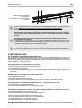
1. UNLOADING
The device should be transported in vertical position, and it should be properly secured and packed. The manufacturer
ships the device on a special wooden platform, secured with cardboard angle sections and foil.
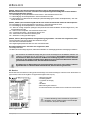
2. PROPERTIES OF THE DEVICE
2.1. Purpose
“Basia 2, Tobi” is a universal cooling device used to store and display a wide assortment of grocery products in singular
packages, previously cooled to storage temperature. Apart from general display cabinets, we also offer display cabinets
for storing fi sh in ice (“FISH” type) and cabinets for displaying vegetable and fruit salads (“GASTRO” type). Our display
cabinets ensure universal and effi cient display area for all types of commercial and gastronomic units. Guaranteed tem-
perature inside the display cabinet equals +2ºC/+8ºC with ambient temperature of +15ºC/+25ºC and relative air humidity
of up to 60%.
2.2. Description of the device
“Basia 2, Tobi” display cabinets have dynamic or static cooling. All types are equipped with automatic defrosting and elec-
tronic thermostat optionally cooperating with temperature recording module enabling to record and signal too low and too
high temperature within the device. There is also an option with automatic condensate evaporation. Together with corned
display cabinets, they may be connected in sequences. “Basia 2, Tobi” display cabinets may be ordered in two versions:
with internal aggregate or to be connected to central aggregate (mod/C). “Basia 2, Tobi” display cabinets are equipped
with storage chamber. “Basia 2, Tobi” display cabinet is available in stationary or moving version. Our devices are made
according to modern technologies and have all certifi cates required by law.
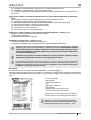
This sign signifi es information of particular meaning for user security and for proper device
exploitation.
Contents List of Figures
List of tables
Table 1 Cross-bars under GN containers
in “Basia Gastro” display cabinet 16
Table 2 Technical data 16 - 17
User manual BASIA 2, TOBI
1. UNLOADING 14
2. PROPERTIES OF THE DEVICE 14
2.1. Purpose 14
2.2. Description of the device 14
2.3. Technical data 16
3. PREPARING THE DEVICE FOR EXPLOITATION 18
3.1. Requirements concerning the place of installation 18
3.2. Connection and actuation 18
4. EXPLOITATION 21
4.1. Temperature regulation 21
5. MAINTENANCE 22
5.1. Cleaning and maintenance 22
6. SERVICE 23
6.1. Fault identifi cation and repair 23
6.2. Service 24
7. THERMOSTAT SERVICE 25
7.1. „IGLOO” thermostat 25
7.2. „CAREL” thermostat 26
en

en
15
User manual Basia 2, Tobiwww.igloo.pl
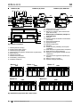
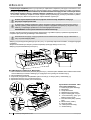
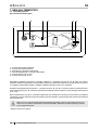
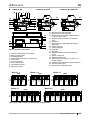
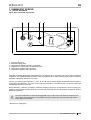
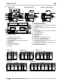
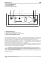
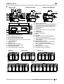
Fig.1 Construction of the device
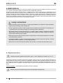
Fig.2 Layout of GN containers in “Basia Gastro” display cabinet
1 – Shelf for handling goods (on the glass)
2 – Bent, front glass, lifted
3 – Glass display shelf
4 – Display shelves (fl at; two-level; three-level)
5 – Front screen
6 – Front fender beam
7 – Front customer shelf
8 – Illuminated front panel
9 – Basis of the device
10 – Aluminium lamp with illumination
11 – Night screens made of plexiglas
12 – Granite working top (made of stainless steel or
furniture board in “Tobi”)
13 – Maximum loading line (sticker on the glass
side!)
14 – Evaporator
15 – Rail (condensate outfl ow after defrosting the
evaporator)
16 – Storing chamber
17 – Cooling aggregate
18 - Data plate
19 – ABS sides
20 – Wooden platform fi xed for transporting the
device
21 – Device levelling feet
22 – Storage chamber doors
23 – Wind brace (when removed – access to con-
denser lamellas)
24 – Control panel (temperature regulator /switches)
25 – Fish tank (“FISH” type)
26 – GN containers (“GASTRO” type)
BASIA 2 (W) BASIA 2 (S) FISH BASIA 2 (W) GASTRO
GN
1/1
GN
1/1
GN
2/4
GN
1/6
GN
1/3
GN
1/3
GN
1/1
GN
1/3
GN
1/1
GN
1/3
GN
1/1
1920
716
716
GN
1/3
GN
1/1
GN
1/3
GN
1/1
GN
1/3
GN
1/1
GN
1/3
GN
1/1
GN
1/3
GN
1/1
GN
1/3
GN
1/1
GN
1/3
GN
1/1
2460
GN
1/3
GN
1/1
GN
1/1
GN
2/4
GN
1/6
GN
1/3
GN
1/3
GN
1/1
GN
1/3
GN
1/1
GN
1/1
GN
2/4
GN
1/6
GN
1/3
GN
1/3
GN
1/1
GN
1/3
GN
1/1
1590
716
GN
1/3
GN
1/1
GN
1/1
GN
2/4
GN
1/6
960
716
Basia 1.1 Basia 1.4 Basia 1.7
Basia 2.1
Basia 2.5
GN
1/3
1290
716
GN
1/3
12 10 1
13
2311
14
15
425 26
5
6
7
8
9
18
19
22
20
21
16
17
24
23

en
16
User manual Basia 2, Tobi www.igloo.pl
Table 1 Cross-bars under GN containers in “Basia Gastro” display cabinet
Name of the device 1.1 GASTRO 1.4 GASTRO 1.7 GASTRO 2.1 GASTRO 2.5 GASTRO
GN cross-bars [amount] 12345
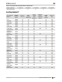
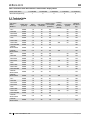
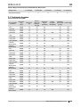
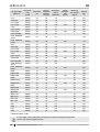
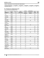
2.3. Technical data
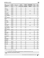
Table 2 Technical data
Type of the
device
“BASIA 2”
Rated volta-
ge [V/Hz]
Rated
current [A]
Rate lighting
power [W]
Electric energ
y
consumption
[kWh/24h]
Cooling
power
demand
[W/mb]
Shelf load
[kg/mb]
Weight of
the device
[kg]
1.1S * 230/50 1,0 18 3,3 - 50 140
1.1S-FISH 230/50 1,0 18 3,3 - 50 150
1.1S-mod/A 230/50 1,0 18 3,3 - 50 124
1.1S-mod/C 230/50 0,1 18 0,3 350 50 106
1.1W * 230/50 1,2 18 3,9 - 50 140
1.1W-mod/A 230/50 1,2 18 3,9 - 50 124
1.1W-mod/C 230/50 0,2 18 0,5 450 50 106
1.1W GASTRO 230/50 1,2 18 3,9 - - 140
1.1W GA-
STRO-mod/A
230/50 1,2 18 3,9 - - 124
1.1W GA-
STRO-mod/C
230/50 0,2 18 0,5 450 - 106
1.4S * 230/50 1,5 30 4,8 - 50 160
1.4S-FISH 230/50 1,5 30 4,8 - 50 175
1.4S-mod/A 230/50 1,5 30 4,8 - 50 144
1.4S-mod/C 230/50 0,1 30 0,4 350 50 126
1.4W * 230/50 1,6 30 5,1 - 50 160
1.4W-mod/A 230/50 1,6 30 5,1 - 50 144
1.4W-mod/C 230/50 0,2 30 0,7 450 50 126
1.4W GASTRO 230/50 1,6 30 5,1 - - 160
1.4W GA-
STRO-mod/A
230/50 1,6 30 5,1 - - 144
1.4W GA-
STRO-mod/C
230/50 0,2 30 0,7 450 - 126
1.7S * 230/50 1,9 36 6,1 - 50 190
1.7S-FISH 230/50 1,9 36 6,1 - 50 205
1.7S-mod/A 230/50 1,9 36 6,1 - 50 173
1.7S-mod/C 230/50 0,2 36 0,5 350 50 155
1.7W * 230/50 2,0 36 6,6 - 50 190
1.7W-mod/A 230/50 2,0 36 6,6 - 50 173
1.7W-mod/C 230/50 0,3 36 1,0 450 50 155
1.7W GASTRO 230/50 2,0 36 6,6 - - 190
1.7W GA-
STRO-mod/A
230/50 2,0 36 6,6 - - 173
1.7W GA-
STRO-mod/C
230/50 0,3 36 1,0 450 - 155

en
17
User manual Basia 2, Tobiwww.igloo.pl
Type of the
device
“BASIA 2”
Rated volta-
ge [V/Hz]
Rated
current [A]
Rate ligh-
ting power
[W]
E
lectric energ
y
consumption
[kWh/24h]
Cooling
power
demand
[W/mb]
Shelf load
[kg/mb]
Weight of
the device
[kg]
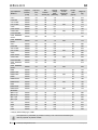
2.1S * 230/50 2,2 58 7,0 - 50 215
2.1S-FISH 230/50 2,2 58 7,0 - 50 230
2.1S -mod/A 230/50 2,2 58 7,0 - 50 195
2.1S -mod/C 230/50 0,3 58 0,8 350 50 177
2.1W * 230/50 2,5 58 8,1 - 50 215
2.1W -mod/A 230/50 2,5 58 8,1 - 50 195
2.1W-mod/C 230/50 0,4 58 1,3 450 50 177
2.1W GASTRO 230/50 2,5 58 8,1 - - 215
2.1W GASTRO-
mod/A
230/50 2,5 58 8,1 - - 199
2.1W GASTRO-
mod/C
230/50 0,4 58 1,3 450 - 177
2.5S * 230/50 2,5 60 8,0 - 50 290
2.5S-FISH 230/50 2,5 60 8,0 - 50 300
2.5S -mod/A 230/50 2,5 60 8,0 - 50 270
2.5S -mod/C 230/50 0,3 60 0,8 350 50 252
2.5W * 230/50 3,2 60 10,2 - 50 290
2.5W -mod/A 230/50 3,2 60 10,2 - 50 270
2.5W-mod/C 230/50 0,5 60 1,6 450 50 252
2.5W GASTRO 230/50 3,2 60 10,2 - - 290
2.5W GASTRO-
mod/A
230/50 3,2 60 10,2 - - 274
2.5W GASTRO-
mod/C
230/50 0,5 60 1,6 450 - 252
NWS 230/50 1,0 18 3,2 - 50 175
NWS-mod/A 230/50 1,0 18 3,2 - 50 160
NWS-mod/C 230/50 0,1 18 0,3 350 50 140
NWW 230/50 1,2 18 3,9 - 50 175
NWW-mod/A 230/50 1,2 18 3,9 - 50 160
NWW-mod/C 230/50 0,2 18 0,5 450 50 140
NZW 230/50 1,5 15 4,9 - 50 150
NZW-mod/A 230/50 1,5 15 4,9 - 50 134
NZW-mod/C 230/50 0,2 15 0,5 450 50 116
ZESTAWY:
(NW+1.1)S 230/50 2,3 36 7,3 - 50 290
(NW+2.1)S 230/50 2,9 76 9,3 - 50 370
(NZ+1.1)S 230/50 1,9 33 6,0 - 50 250
(NZ+2.1)S 230/50 2,9 73 9,3 - 50 320
3.0S 230/50 3,4 76 11,1 - 50 337
3.0W 230/50 4,3 88 13,8 - 50 337
3.4S 230/50 3,5 72 11,3 - 50 357
3.4W 230/50 4,6 72 14,9 - 50 364
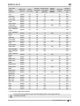
* - Concerns also “TOBI” display cabinets
In devices with illuminated front panel, the rated lighting power is twice bigger than the
one stated in the table!

en
18
User manual Basia 2, Tobi www.igloo.pl
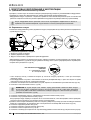
3. PREPARING THE DEVICE FOR EXPLOITATION
3.1. Requirements concerning the place of installation
• Verify whether the cross section of feeding conduits is proper for power consumption of the installed device.
• It is forbidden to connect the device by extension rods or dividers.
• The device should be connected to the separate, properly made electric circuit with plug-in socket with protecting pin
(according to PBUE /Regulations concerning Electric Equipment Construction/)
The device may be actuated solely after confi rmation of the fi re protection effi ciency with results of measu-
res performed according to binding regulations!
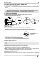
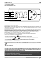
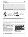
3.2. Connection and actuation
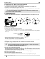
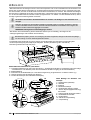
• Unpack the device and remove the wooden platform from the basis (does not concern moving devices) Fig.3 (p.18)
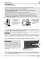
Fig.3 Removing the wooden platform
1 – Unscrew the feet from the platform
2 – Remove the wooden platform
3 – Screw the feet in nuts welded to the frame of the device
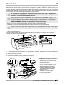
• Place the display cabinet on an even basis, which is hard enough, and then level it with feet.
In case of moving devices it is necessary to use wheel blockage in order to immobilise the device during exploitation
Fig.4 (p.18)
Fig.4 Wheel system, moving
system
A – moving position
B – blockade
• Remove the protection foil from the elements of the device (f. ex. from
the inside of the device, display shelves and front fender beam)
• If the user shall obtain a device partially disassembled to secure it during transportation, perform the following ope-
rations:
1. Mount display shelves or fi sh tanks, hanging them on aluminium angle sections Fig.5/4;5 (p.19)
2. Mount glass sides Fig.6/2;1 (p.19)
NOTE: In case of “Gastro” display cabinets, it is necessary to pull out the universal salad tank before
mounting the glass side Fig.5 (p.19), in order to obtain free access to ABS side and to enable easy
glass side with the help of glass holding downs Fig.6/1 (p.19).
3. Mount the aluminium lamp (together with lighting) on glass sides Fig.6/3 (p.19)
4. Mount the casing of lamp conduit Fig.6/10 (p.19)
Move the casing of lamp conduit to the back of the glass side, in order to hide the conduit coming out of the lamp in
the casing and to place it on the internal part of the glass side!
5. (This concerns only “GASTRO” display cabinet) Place universal salad tank in the display cabinet. Place cross-bars
under GN containers in module tank, and then place GN containers according to Fig.2 (p.15)
6. Mount front screen Fig.6/8 (p.19)
7. Mount front glasses of the display cabinet Fig.6/5 (p.19)
8. Mount night screens Fig.7/1; 2 (p.20)
9. Place the condensate container on the basis of the device according to Fig.8/3 (p.20) or Fig.9/3 (p.20)
A
B
123

en
19
User manual Basia 2, Tobiwww.igloo.pl
3
5342
2
1
5
6
7
11
1
10
10
2
1
8
9
5
4
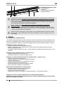
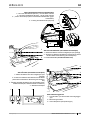
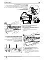
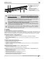
Fig.5 Mounting salad tank in “Basia Gastro” display cabinet
1 – Universal salad tank (for each length of the cabinet) – used as addition in order to disassembly salad tanks and
glass side (after pulling the tank – access to glass holding downs)
2 – Module salad tank
3 – Cross-bars under GN containers (placed only in the tank (2), does not concern the universal tank (1))
4 – Anterior aluminium angle section (at the back of the body)
5 - Posterior aluminium angle section (at the front of the body)
Fig.6 Assembly of glass elements
and aluminium lamp
1 – Glass (glass side) holding down
2- Glass side
3 – Aluminium lamp
4 – Aluminium lamp hole plug
5 – Bent, front glass, lifted
6 – Upper aluminium profi le of the glass (lifted
guide)
7 – Lower aluminium profi le of the glass
(catch)
8 – Front, glass screen
9 – Front bracket
10 - Lamp conduit protection
11 – Lamp conduit
• Place the plug of the connecting cable directly in plug-in socket (it is forbidden to connect the device by means of
extension cords or dividers!)
Power sockets (optional) may be used to power cash register, weight, and similar receivers with power not
exceeding 500W!
• Turn on the main switch Fig.10/1 (p.20), which activates the temperature regulator, and then aggregate of the device
• Set the temperature on thermostat control panel Fig.10/3(p.20) (service details on p.25 or 26)
• Turn on the lighting switch Fig.10/2 (p.20)
• The fi rst cleaning of the device should be provide right after unpacking, and before turning it on. The unit should
be cleaned with water at a temperature not exceeding 40°C with a neutral detergent. For washing and cleaning
the equipment it is prohibited to use products containing chlorine and sodium varieties, which destroy the protecti-
ve layer and components of the device! Any residue of adhesives or silicone on metal elements should be remo-
ved only with extraction naphtha (not applicable to items made of plastic !). Do not use other organic solvents.
When cleaning the unit is prohibited to use water jet. The unit should be cleaned with a wet rag.
After installation of the device at the destination place it should be left to rest for at least 2 hours before
turning it on (for devices with built in compressor) to set the level of refrigerant in order to prevent problems
with starting up the aggregate.
WARNING: Keep out the cooling circuit from damage!

en
20
User manual Basia 2, Tobi www.igloo.pl
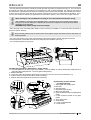
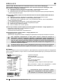
Fig.7 Assembly/disassembly of night screens
1 - Lower night screen (shorter one) – mounted as the fi rst one
2 - Upper night screen (longer one) – mounted as the second one
3 - “Leaf” of the aluminium lamp (hides and secures the night screens before
falling out)
4 - Night screen guide (aluminium profi le)
Fig.8 Condensate container (version without evaporator)
1 – Water outlet from the body of the device (water-sealed)
2 – Rail water outlet hose (condensate outfl ow after defrosting
the evaporator)
3 - Condensate container (empty the condensate!!!)
Fig.9 Overfl ow (version with evaporator)
1 – Water outlet from the body of the device (water-sealed)
2 – Rail water outlet hose (condensate outfl ow after defro-
sting the evaporator)
3 – Overfl ow (it is necessary to empty the condensate,
when water overfl ows the evaporator container!)
4 - Evaporator
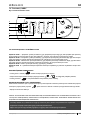
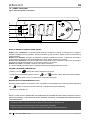
Fig.10 Control panel of the device
1 - Main switch (turns on/off the aggregate of the
device)
2 – Lighting switch
3 - Thermostat (temperature regulator) panel (service
details in Chapter No. 7 p. 25 or 26)
1
2
3
1
3
2
4
1 23
4
3
2
1
1
2
1
2

en
21
User manual Basia 2, Tobiwww.igloo.pl
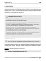
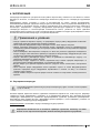
4. EXPLOITATION
Temperature of the cooled space and aggregate operating cycle may fl uctuate. It depends on numerous factors,
such as amount and temperature of products placed in the device and temperature of the surroundings.
The device should be placed in a dry and well-ventilated place, ensuring proper air exchange (distance between the
wall and the device – min. 10 cm), out of sunlight, kept far from heat sources and devices enforcing air fl ow (ceiling
and portable ventilators, blow-in heaters). The device functions properly in a room, where temperature falls within
appropriate climatic class stated on the data plate. The operation of the device may worsen when it shall operate in
temperature lower or higher than the stated temperature range.
Remarks and indications
• It is necessary to properly level the display cabinet, which will prevent loud operation of the device and shall
ensure proper water (condensate) outfl ow during defrosting.
• After transporting the device, wait about 2 hours before its actuation.
• The fi rst fi lling of cooling space should be performed after its previous cooling to working temperature. This
principle should also be observed after longer pause in exploitation.
• Do not block any ventilation holes, which would hamper circulation of the cooled air. It is also necessary to
ensure proper airfl ow around the device (aggregate ventilation holes cannot be covered).
• Ensure even load on shelves, do not exceed their maximal load and do not exceed maximal loading.
• Keep the condenser clean. Impurities may lead to overheating of the compressor and as a consequence may
result in damage of the device, which is not covered by warranty.
• Do not use electric devices inside grocery product storing chamber.
• After closing the door of the device, it is not recommended to open it with force. Negative pressure created
inside the device is levelled within 1-2 minutes, which allows easy opening of the door.
• Avoid unnecessary opening of doors and leaving them open for a longer period of time.
4.1. Temperature regulation
Service of “Igloo” and “Carel” thermostat (temperature regulators) is described in chapter 7 (p. 25 and 26)
The basic aim of a thermostat is to control the cooling aggregate to obtain the set temperature within the device and
maintain it within the determined temperature ranges. The producer enters all settings of temperature regulators required
for normal functioning of the device. Before primary actuation the user should control and possibly set the required tem-
perature inside the device on the control panel.
Digital display – displays the current temperature inside the device.
It is forbidden to interfere with systemic parameters of the thermostat, as this can lead to serious
consequences, including the damage of the cooling device!

en
22
User manual Basia 2, Tobi www.igloo.pl
When using the display cabinet, as well as during maintenance works, pay attention not to destroy the
temperature sensor in the evaporator screen!
It is recommended to make a break in the exploitation of the device once a month in order to clean its interior,
naturally defrost the evaporator, clean the condenser and verify the condition of door seals.
If the device is not equipped with automatic condensate evaporation, it is essential to remove the condensate from the
container when fi lling the container Fig.8 (p.20). The number (frequency) of condensate removal depends on device
exploitation conditions (f. ex. air humidity, door opening frequency, the amount and temperature of products entered for
storage).
Do not use mechanical agents in order to fasten the defrosting process!
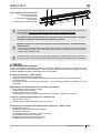
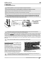
It is essential to keep the condenser of the device cle-
an. Dirt may hinder the heat exchange, causing mainly
increase in electric energy consumption and may cause
damage of aggregate compressor.
In order to clean the condenser it is necessary to
unscrew the fi xing sheet metal screws and pull the wind
brace out. Clean condenser lamellas with help of soft
brush or paint brush. If the condenser is extremely dirty
(blocked lamellas) it is indicated to use vacuum cleaner
or compressed nitrogen to suck / blow the dirt from be-
tween lamellas.
The producer shall not be held responsible for damages of the condenser aggregate resulting from non-
observance of condenser cleanliness!
5. MAINTENANCE
5.1. Cleaning and maintenance
All maintenance services need to be performed after disconnecting the device from power supply!
Protect electric installation against any damage or water spillage
Do not use water stream to clean the device, only a wet cloth
Do not use any sharp objects to remove dirt!
Devices with wheels cannot be used on uneven surfaces!
During cleaning the inside of the device do not leave the front glass freely lifted in the aluminium profi le. This may
cause the damage of the glass and is not covered by warranty. Please remove the glass with profi le for the time of
cleaning Fig. 11 (p.22).
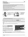
3
2
1
Fig.11 Front glass disassembly
1 - Front glass
2 - Upper aluminium profi le of the
glass (lifted guide)
3 - Lower aluminium profi le of the
glass (catch)
Fig.12 Temperature sensor
inside the device
1 – Temperature sensor
2 – Evaporator screen
3 – Evaporator drip rail
Fig.13 Cleaning the condenser
123

en
23
User manual Basia 2, Tobiwww.igloo.pl
Door seal should be cleaned solely with clean water without any cleansing agents and it should be
thoroughly dried. The seal cannot get into contact with oily substances or grease!
Control whether door close properly during maintenance procedures.
Test: place a sheet of paper between the seal and the casing and close the door. The paper
should pose a tangible resistance during an attempt to pull it out.
Elements of device can corrode when improper used and maintenance. To avoid that please
follow the rules:
• Do not allow contact of the surface of the device with substances containing chlorine and / or baking
soda in different varieties, which destroy the protective layer and components of the device (also
includes various stainless steel)
During maintenance services it is necessary to pay attention not to damage the data place of the device
Fig.15 (p.24), which contains signifi cant information for servicing organs and waste removal companies.
6. SERVICE
6.1. Fault identifi cation and repair
In case of any diffi culties during actuation of the device or during its exploitation, please return to these chapters in this
manual, which explain the performed operation. This aims to ensure that the device is properly operated. If you still
experience diffi culties, the following hints will help you solve the problem.
The device is not working... – Make sure that:
• The device is connected to the supply network
• Voltage and frequency in the network are compliant with those recommended by the producer 230V/50Hz
• The main switch is on
• Thermostat is on (This concerns the Igloo thermostat – If only two spots are visible on the display – turn on the
thermostat)
Water leakage from below the device or into the inside of the chamber:
• Check whether the device is properly levelled
• Check the patency of outfl ow pipes
• Empty the condenser tray or container
• Check whether there is not too much ice in the rail and on the condenser – defrost when necessary
The device is operating, but the lighting is off...– Make sure that:
• Lighting switch is turned on
• Fluorescent lamp or starting switch of the device are not burnt
The device does not reach the proper temperature, the lighting is on...– Make sure that:
• Lighting switch is turned on
• Temperature setting on the thermostat is properly set
• Thermostat works properly
• The condenser is clean, if necessary – clean the condenser
• Ambient temperature does not exceed 25ºC
• Enough time has passed for products to be cooled
• Ventilation holes of the device are not blocked
Fig.14 Changing the fl uorescent lamp
1 – Fluorescent lamp handle
2 – Fluorescent lamp
3 – Casing of fl uorescent lamp and
starting switch
4 – Starting switch of fl uorescent lamp
34
21

en
24
User manual Basia 2, Tobi www.igloo.pl
Noises made by the operating device are a normal phenomenon. The devices are equipped with ventila-
tors, engines and compressors, which turn on and off automatically. Each compressor makes certain
noises when operating. These sounds are made by the aggregate engine and by cooling agent
fl owing through the circuit. This phenomenon constitutes a technical feature of cooling devices
and it does not signify their faulty work.
Steam precipitation on glasses of the device is a normal phenomenon in case of high relative air
humidity exceeding 60% and does not require calling the service!
6.2. SERVICE
If after checking points described in chapter 6.1 „Fault identifi cation and repair” the device still does not work properly, please
contact Technical Service of the Igloo company, stating the data from the data plate Fig.15 (p.24):
• Serial number (NS)
• Production date
• Type (name of the device)
and
• Date when the device was purchased
• Description of the problem
• Your exact address and telephone number (with the code number)
Data plate is placed at the back of the device, in the right upper cor-
ner below the top Fig.1/18 (p.15)
The above fi gure shows a demonstrative data plate
and the data stated on the plate are exemplary data,
which are not related with “Basia 2” device!
(This concerns the “IGLOO” thermostat) thermostat displays C0 or C1 or C2 instead of displaying temperature:
This situation shall occur, when one of temperature regulation sensors has been destroyed.
The following messages may be displayed in such case:
• C0 – temperature sensors inside the chamber are damaged – call authorized service
• C1 – failure of evaporator sensor - call authorized service
• C2 – failure of condenser alarm sensors (or failure of second evaporator sensor) – call authorized service
(This concerns the “CAREL” thermostat) Thermostat displays E0 or E1 or L0 or HI or EE or Ed or DF instead of temperature:
• E0 – temperature sensor inside the chamber is damaged – call authorized service
• E1 – failure of evaporator sensor - call authorized service
• L0 – low temperature alarm (lower than temperature range set within the device – call authorized service
• HI – high temperature alarm – call authorized service
• EE – internal defect of the regulator – call authorized service
• Ed – max. defrosting time exceeded
• DF – defrosting in progress (this is not an alarm signal)
(This concerns the “IGLOO” thermostat) The device is working, sound signalling is activated...– Make sure that:
• The condenser is clean, if necessary – clean the condenser
• Condenser ventilator is working properly
• Ambient temperature does not exceed 25ºC
The device is working too loud...– Make sure that:
• The device is standing stably
• Furniture adjoining the device do not vibrate when the cooling aggregate compressor is working
Fig.15 Data plate

en
25
User manual Basia 2, Tobiwww.igloo.pl
7. THERMOSTAT SERVICE
7.1. „IGLOO” thermostat
Fig.16 „Igloo” thermostat control panel
Verifi cation of adjusted temperature (inside the device) – By pressing “▲” or “▼” switch once we can verify the adjusted
temperature. The adjusted temperature shall be shown on the display with a visible red blinking spot (diode). The preview
shall fi nish automatically after about 3 seconds.
Lowering (or increasing) the temperature – press “▼” (or “▲”) switch and the adjusted temperature shall be visible on
control panel. By pressing the “▼” switch we decrease the temperature to the desired value. The preview shall fi nish
automatically after about 3 seconds.
Manual defrosting – switch No. 2 enables to initiate the defrosting cycle at any moment when the device is working (re-
gardless of the automatic defrosting function); the switch shall not operate when the temperature is higher than the fi nal
defrosting temperature.
The user should switch on/ switch off the aggregate only by means of the main switch of the device, and
not by means of the direct switch on thermostat control panel. Switching on the main switch shall automa-
tically initiate the thermostat!
* Read more on www.igloo.pl
1 – Cooling on/off switch
2 – Manual defrosting switch
3 – Aggregate and defrosting operating control diode
4 – Temperature monitoring switch on defrosting sensor
5 – Temperature regulation switch (increase)
6 – Temperature regulation switch (decrease)
2134 65

en
26
User manual Basia 2, Tobi www.igloo.pl
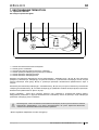
7.2. „CAREL” thermostat
Fig.17 „Carel” thermostat control panel
WHAT DO DIODES ON CONTROL PANEL SIGNIFY
Diode 1 is on - Compressor: the symbol is visible when the compressor is working. It is blinking when compressor
actuation is delayed by security procedure. It blinks in the following cycle: two blinks – pause, when the constant working
mode is activated.
Diode 2 is on - Ventilator: the symbol is visible when evaporator ventilators are turned on. It blinks when the actuation
of the ventilators is delayed by external disengagement or when another procedure is in progress.
Diode 3 is on - Defrosting: the symbol is visible when the defrosting function is activated. It blinks when the actuation
is delayed by external disengagement or when another procedure is in progress.
Diode 4 is on - Alarm: the symbol is visible when the alarm is activated.
5 – current temperature inside the device is displayed (decimal places displayed after the comma)
SETTING THE DESIRED TEMPERATURE
- press for 1 second
leading value shall be displayed on the screen;
- increase or decrease the leading value by means of and , switches, until the desired value shall be obtained
;
- press
once again in order to confi rm the new value of the setting point;
MANUAL INPUT OF THE DEFROSTING CYCLE
Defrosting shall be realised in an automatic mode. It is possible to force defrosting at any moment by pressing and holding
the
switch for minimum 5 seconds. Diode No. 1 shall blink during manual defrosting.
* Read more on www.alfaco.pl
NOTE: IN CASE OF NOT OBSERVING THE PRINCIPLES ON CONNECTING AND USING THE DEVICE INCLU-
DED IN THIS MANUAL, THE PRODUCER SHALL RESERVE THE RIGHT TO RECEDE FROM OBLIGATIONS OF
THE GUARANTOR!!!
Information included in this document may be altered by “IGLOO” without noticing the user.
Copying the present manual without the consent of the producer is forbidden.
Images and drawings are of demonstrative character and may differ from the purchased device.
1
2
3
4
5
Page is loading ...
Page is loading ...
Page is loading ...
Page is loading ...
Page is loading ...
Page is loading ...
Page is loading ...
Page is loading ...
Page is loading ...
Page is loading ...
Page is loading ...
Page is loading ...
Page is loading ...
Page is loading ...
Page is loading ...
Page is loading ...
Page is loading ...
Page is loading ...
Page is loading ...
Page is loading ...
Page is loading ...
Page is loading ...
Page is loading ...
Page is loading ...
Page is loading ...
Page is loading ...
-
 1
1
-
 2
2
-
 3
3
-
 4
4
-
 5
5
-
 6
6
-
 7
7
-
 8
8
-
 9
9
-
 10
10
-
 11
11
-
 12
12
-
 13
13
-
 14
14
-
 15
15
-
 16
16
-
 17
17
-
 18
18
-
 19
19
-
 20
20
-
 21
21
-
 22
22
-
 23
23
-
 24
24
-
 25
25
-
 26
26
-
 27
27
-
 28
28
-
 29
29
-
 30
30
-
 31
31
-
 32
32
-
 33
33
-
 34
34
-
 35
35
-
 36
36
-
 37
37
-
 38
38
-
 39
39
-
 40
40
-
 41
41
-
 42
42
-
 43
43
-
 44
44
-
 45
45
-
 46
46
-
 47
47
-
 48
48
-
 49
49
-
 50
50
-
 51
51
-
 52
52


Igloo BASIA 2 User manual
- Type
- User manual
Ask a question and I''ll find the answer in the document
Finding information in a document is now easier with AI
in other languages
- Deutsch: Igloo BASIA 2 Benutzerhandbuch
- русский: Igloo BASIA 2 Руководство пользователя
- polski: Igloo BASIA 2 Instrukcja obsługi
Related papers
Other documents
-
 Multi-Contact M-1GN-GG Installation guide
-
Tobi 657573 User guide
-
Tobi KB-1126 User manual
-
-
Ferm CRM1012 FC-700F - 242650 Owner's manual
-
-
 Multi-Contact M-1LR-GG Installation guide
-
Thane Tobi Steam Wand Owner's manual
-
-
Sunpentown SF614P User manual

