
Part No. P0993133 03
Business Communications
Manager
BCM200/400
Installation and Maintenance
Guide

2
P0993133 03
Copyright © 2002 Nortel Networks
All rights reserved. November, 2002.
The information in this document is subject to change without notice. The statements, configurations, technical data, and
recommendations in this document are believed to be accurate and reliable, but are presented without express or implied
warranty. Users must take full responsibility for their applications of any products specified in this document. The
information in this document is proprietary to Nortel Networks NA Inc.
Trademarks
NORTEL NETWORKS and Business Communications Manager, are trademarks of Nortel Networks NA Inc.
Microsoft, MS, MS-DOS, Windows, and Windows NT are registered trademarks of Microsoft Corporation.
Symbol, Spectrum24, and NetVision are registered trademarks of Symbol Technologies, Inc.
All other trademarks and registered trademarks are the property of their respective owners.
North American Regulatory Information
Safety
Business Communications Manager equipment meets all applicable requirements of both the CSA
C22.2 No. 950-95 and UL-1950 Edition 3.
Danger: Risk of shock.
Read and follow installation instructions carefully.
Ensure the Business Communications Manager and Business Communications Manager
expansion unit are unplugged from the power socket and that any telephone or network
cables are unplugged before opening the Business Communications Manager or Business
Communications Manager expansion unit.
If installation of additional hardware and /or servicing is required, disconnect all telephone
cable connections prior to unplugging the Business Communications Manager.
Ensure the Business Communications Manager and Business Communications Manager
expansion unit are plugged into the wall socket using a three-prong power cable before
any telephone cables are connected.

3
Installation and Maintenance Guide
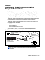
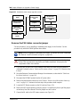
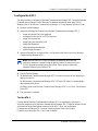
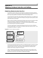
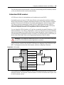
Enhanced 911 Configuration
Radio-frequency Interference
Caution: Only qualified persons should service the system.
The installation and service of this hardware is to be performed only by service personnel
having appropriate training and experience necessary to be aware of hazards to which they
are exposed in performing a task and of measures to minimize the danger to themselves or
other persons.
Electrical shock hazards from the telecommunication network and AC mains are possible
with this equipment. To minimize risk to service personnel and users, the Business
Communications Manager system must be connected to an outlet with a third-wire ground.
Service personnel must be alert to the possibility of high leakage currents becoming
available on metal system surfaces during power line fault events near network lines. These
leakage currents normally safely flow to Protective Earth ground via the power cord.
Therefore, it is mandatory that connection to an earthed outlet is performed first and
removed last when cabling to the unit. Specifically, operations requiring the unit to be
powered down must have the network connections (central office lines) removed first.
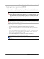
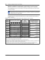
Caution: Warning
Local, state and federal requirements for Emergency 911 services support by Customer
Premises Equipment vary. Consult your telecommunication service provider regarding
compliance with applicable laws and regulations.
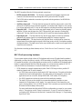
Note: For information about 911 configuration, refer to the Enhanced 911 (E911)
Configuration section in the Business Communications Manager 3.0 Programming
Operations Guide.
Warning: Equipment generates RF energy.
This equipment generates, uses, and can radiate radio-frequency energy. If not installed
and used in accordance with the installation manual, it may cause interference to radio
communications. It has been tested and found to comply with the limits for a Class A
computing device pursuant to Part 15 of the FCC Rules and with ICES.003, CLASS A
Canadian EMI Requirements. Operation of this equipment in a residential area is likely to
cause interference, in which case the user, at his or her own expense, will be required to
take whatever measures may be required to correct the interference.

4
P0993133 03
Telecommunication Registration
Business Communications Manager equipment meets all applicable requirements of both Industry
Canada CS-03 and US Federal Commission FCC Part 68 and has been registered under files
Industry Canada 332D-5980A and FCC US:AB6KF15B20705 (key system),
US:AB6MF15B20706 (hybrid system), and US:AB6PF15B23740 (PBX system). Connection of
the Business Communications Manager telephone system to the nationwide telecommunications
network is made through a standard network interface jack that you can order from your local
telecommunications company. This type of customer-provided equipment cannot be used on party
lines or coin lines.
Before installing this equipment, users should ensure that it is permissible to be connected to the
facilities of the local telecommunications company. The equipment must also be installed using an
acceptable method of connection. The customer should be aware that compliance with the above
conditions may not prevent degradation of service in some situations.
Repairs to certified equipment should be made by an authorized maintenance facility designated
by the supplier. Any repairs or alterations made by the user to this equipment, or equipment
malfunctions, may give the telecommunications company cause to request the user to disconnect
the equipment. Users should ensure for their own protection that the electrical ground connections
of the power utility, telephone lines and internal metallic water pipe system, if present, are
connected together. This precaution may be particularly important in rural areas.
Caution: Users should not attempt to make such connections themselves, but
should contact the appropriate electric inspection authority, or electrician.

5
Installation and Maintenance Guide
Network Connection
Canada and US
Hearing Aid Compatibility
Business Communications Manager telephones are hearing-aid compatible, as defined in Section
68.316 of Part 68 FCC Rules.
Electromagnetic Compatibility
Business Communications Manager equipment meets all FCC Part 15, Class A radiated and
conducted emissions requirements.
Business Communications Manager does not exceed the Class A limits for radiated and conducted
emissions from digital apparatus as set out in the Radio Interference Regulations of Industry
Canada.
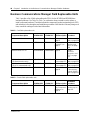
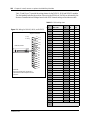
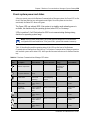
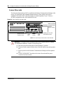
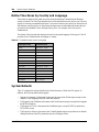
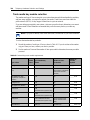
Telephone Company Registration
It is usually not necessary to call the telecommunications company with information on the
equipment before connecting the Business Communications Manager system to the telephone
network. If the telecommunications company requires this information, provide the following:
• telephone number(s) to which the system will be connected
• FCC registration number (on label affixed to Business Communications Manager)
• universal service order code (USOC)
• service order code (SOC)
• facility interface code (FIC)
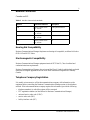
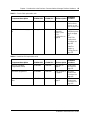
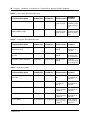
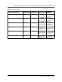
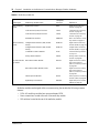
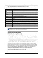
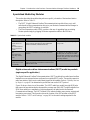
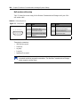
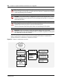
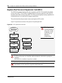
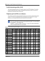
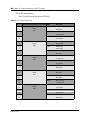
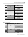
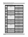
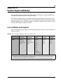
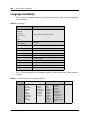
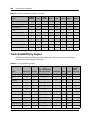
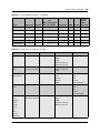
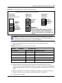
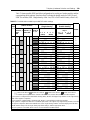
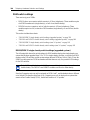
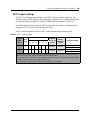
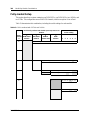
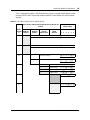
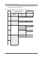
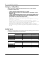
Table 1 Interface harmonized standards
Interface Harmonized Standard Description
CTM Industry Canada CS03
FCC Part 68
Analog terminal device
DTM Industry Canada CS03
FCC Part 68
T1 and Primary Rate ISDN
BRIM Industry Canada CS03
FCC Part 68
Basic Rate ISDN
WAN Industry Canada CS03
FCC Part 68
T1

6
P0993133 03
Use of a Music Source
In accordance with U.S. Copyright Law, a license may be required from the American Society of
Composers, Authors and Publishers, or similar organization if Radio or TV broadcasts are
transmitted through the Music On Hold or Background Music features of this telecommunication
system.
Nortel Networks hereby disclaims any liability arising out of the failure to obtain such a license.
Rights of the Telecommunications Company
If the Business Communications Manager system is causing harm to the telephone network, the
telecommunications company may discontinue service temporarily. If possible, the
telecommunications company will notify you in advance. If advance notice is not practical, the
user will be notified as soon as possible. The user will be given the opportunity to correct the
situation and informed of the right to file a complaint to the FCC.
The telecommunications company may make changes in its facilities, equipment, operations or
procedures that could affect the proper functioning of the system. If this happens, the
telecommunications company will give you advance notice in order for you to make any necessary
modifications to maintain uninterrupted service.
Repairs
In the event of equipment malfunction, all repairs to certified equipment will be performed by an
authorized supplier.
Canadian Regulations - please read carefully
Notice
The term "IC" before the certification number located on the host equipment only signifies that the
Industry Canada technical specifications were met. The Department does not guarantee the
equipment will operate to the user’s satisfaction. Before installing this equipment, users should
ensure that it is permissible to be connected to the facilities of the local telecommunications
company. The equipment must also be installed using an acceptable method of connection. The
customer should be aware that compliance with the above conditions may not prevent degradation
of service in some situations. Repairs to certified equipment should be coordinated by a
representative designated by the supplier. Any repairs or alterations made by the user to this
equipment, or equipment malfunctions, may give the telecommunications company cause to

7
Installation and Maintenance Guide
request the user to disconnect the equipment. Users should ensure for their own protection that the
electrical ground connections of the power utility, telephone lines and internal metallic water pipe
system, if present, are connected together. This precaution may be particularly important in rural
areas.
Notice
The Ringer Equivalence Number (REN) assigned to each terminal device provides an indication of
the maximum number of terminals allowed to be connected to a telephone interface. The
termination on an interface may consist of any combination of devices subject only to the
requirement that the sum of the RENs of all the devices does not exceed 5.
This Class A device complies with Part 68 & Part 15 of the FCC Rules and ICES-003 Class A
Canadian EMI requirements. Operation is subject to the following two conditions (1) This device
may not cause harmful interference and (2) this device must accept any interference received,
including interference that may cause undesired operation.
Do not attempt to repair this equipment. If you experience trouble, write for warranty and repair
information:
Nortel Networks
30 Norelco Drive, Weston, Ontario
M9L 2X6 Canada
US Regulations - please read carefully
Federal Communications Commission (FCC) Notice
FCC registration number: This telephone equipment complies with Part 68, Rules and
Regulations, of the FCC for direct connection to the Public Switched Telephone Network. (The
FCC registration number appears on a sticker affixed to the bottom of the telephone.)
Your connection to the telephone line must comply with these FCC rules:
• An FCC compliant telephone cord and modular plug is provided with this equipment. This
equipment is designed to be connected to the telephone network premises wiring using a
compatible modular jack which is Part 68 compliant. See installation instructions for details.
• Use only an FCC Part 68-compliant Universal Service Order Code (USOC) network interface
jack, as specified in the installation instructions, to connect this telephone to the telephone
line. (To connect the phone, press the small plastic tab on the plug at the end of the phone’s
line cord. Insert into a wall or baseboard jack until it clicks. To disconnect, press the tab and
pull out.) See installation instructions for details.
Caution: Users should not attempt to make such connections themselves, but should
contact the appropriate electric inspection authority, or electrician, as appropriate.

8
P0993133 03
• If the terminal equipment causes harm to the telephone network, the telephone company will
notify you in advance that temporary discontinuance of the product may be required. But if
advance notice isn’t practical, the telephone company will notify you as soon as possible. You
will also be advised of your right to file a complaint with the FCC, if you believe it is
necessary.
• If a network interface jack is not already installed in your location, you can order one from
your telephone company. Order the appropriate USOC Network interface jack, as specified in
the installation instructions, for wall-mounted telephones or for desk/table use. In some states,
customers are permitted to install their own jacks.
• Your telephone may not be connected to a party line or coin telephone line. Connection to
Party Line Service is subject to state tariffs. (Contact the state public utility commission,
public service commission or corporation commission for information.)
• It is no longer necessary to notify the Telephone Company of your phone’s Registration and
REN numbers. However, you must provide this information to the telephone company if they
request it. The telephone company may make changes in its facilities, equipment, operation or
procedures that could affect the operation of the equipment. If this happens the telephone
company will provide advance notice in order for you to make necessary modification to
maintain uninterrupted service.
• Do not attempt to repair this equipment. If you experience trouble, write for warranty and
repair information:
Nortel Networks
640 Massman Drive,
Nashville, TN, 37210, USA
Ringer Equivalence Number
The FCC Registration label (on bottom of phone), includes a Ringer Equivalence Number (REN),
which is used to determine the number of devices you may connect to your phone line. A high total
REN may prevent phones from ringing in response to an incoming call and may make placing calls
difficult. In most areas, a total REN of 5 should permit normal phone operation. To determine the
total REN allowed on your telephone line, consult your local telephone company.
Hearing Aids
This phone is compatible with hearing aids equipped with an appropriate telecoil option.
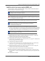
Programming Emergency Numbers
When programming emergency numbers and/or making test calls to emergency numbers:
1 Remain on the line and briefly explain to the dispatcher the reason for calling before hanging
up.
2 Perform such activities in the off-peak hours, such as early mornings or late evenings.

9
Installation and Maintenance Guide
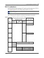
EMI/EMC (FCC Part 15)
• Reorient or relocate the receiving antenna.
• Increase the separation between the equipment and receiver.
• Connect the equipment into an outlet on a circuit different from that to which the receiver is
connected.
• Consult the dealer or an experienced radio/TV technician for help.
Changes or modifications not expressly approved by the party responsible for compliance could
void the user’s authority to operate the equipment.
Important Safety Instructions
The following safety instructions cover the installation and use of the Product. Read carefully and
retain for future reference.
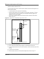
Installation
1 Never install telephone wiring during a lightning storm.
2 Never install telephone jacks in wet locations unless the jack is specifically designed for wet
locations.
3 Never touch uninsulated telephone wires or terminals unless the telephone line has been
disconnected at the network interface.
4 Use caution when installing or modifying telephone lines. The exclamation point within an
equilateral triangle is intended to alert the user to the presence of important operating and
maintenance (servicing) instructions in the literature accompanying the product.
Note: This equipment has been tested and found to comply with the limits for a
Class A digital device, pursuant to Part 15 of the FCC Rules. These limits are
designed to provide reasonable protection against harmful interference in a
residential installation. This equipment generates, uses and can radiate radio
frequency energy and, if not installed and used in accordance with the
instructions, may cause harmful interference to radio communications. However,
there is no guarantee that interference will not occur in a particular installation. If
this equipment does cause harmful interference to radio or television reception,
which can be determined by turning the equipment off and on, the user is
encouraged to try to correct the interference by one or more of the following
measures:
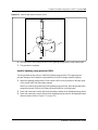
Warning: To avoid electrical shock hazard to personnel or equipment damage observe the
following precautions when installing telephone equipment:

10
P0993133 03
This symbol on the product is used to identify the following important information: Use only
with a CSA or UL certified CLASS 2 level C power supply, as specified in the user guide.
Use
When using your telephone equipment, basic safety precautions should always be followed to
reduce risk of fire, electric shock and injury to persons, including the following:
1 Read and understand all instructions.
2 Follow the instructions marked on the product.
3 Unplug this product from the wall outlet before cleaning. Do not use liquid cleaners or aerosol
cleaners. Use a damp cloth for cleaning.
4 Do not use this product near water, for example, near a bath tub, wash bowl, kitchen sink, or
laundry tub, in a wet basement, or near a swimming pool.
5 Do not place this product on an unstable cart, stand or table. The product may fall, causing
serious damage to the product.
6 This product should never be placed near or over a radiator or heat register. This product
should not be placed in a built-in installation unless proper ventilation is provided.
7 Do not allow anything to rest on the power cord. Do not locate this product where the cord will
be abused by persons walking on it.
8 Do not overload wall outlets and extension cords as this can result in the risk of fire or electric
shock.
9 Never spill liquid of any kind on the product.
10 To reduce the risk of electric shock do not disassemble this product, but have it sent to a
qualified service person when some service or repair work is required.
11 Unplug this product from the wall outlet and refer servicing to qualified service personnel
under the following conditions:
a When the power supply cord or plug is damaged or frayed.
b If the product has been exposed to rain, water or liquid has been spilled on the product,
disconnect and allow the product to dry out to see if it still operates; but do not open up the
product.
c If the product housing has been damaged.
d If the product exhibits a distinct change in performance.
12 Avoid using a telephone during an electrical storm. There may be a remote risk of electric
shock from lightning.
13 Do not use the telephone to report a gas leak in the vicinity of the leak.
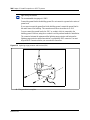
14 Caution: To eliminate the possibility of accidental damage to cords, plugs, jacks, and the
telephone, do not use sharp instruments during the assembly procedures.
15 Warning: Do not insert the plug at the free end of the handset cord directly into a wall or
baseboard jack. Such misuse can result in unsafe sound levels or possible damage to the
handset.

11
Installation and Maintenance Guide
16 Save these instructions.
International Regulatory Information
This is a class A product. In a domestic environment this product may cause radio interference in
which case the user may be required to take adequate measures.
Hereby, Nortel Networks declares that Enterprise Edge/Business Communications Manager
Model No. NT7B10xxxx, is in compliance with the essential requirements and other relevant
provisions of Directive 1999/5/EC.
Information is subject to change without notice. Nortel Networks reserves the right to make changes in design
or components as progress in engineering and manufacturing may warrant. This equipment has been tested
and found to comply with the European Safety requirements EN 60950 and EMC requirements EN 55022
(Class A) and EN 55024. These EMC limits are designed to provide reasonable protection against harmful
interference when the equipment is operated in a commercial and light industrial environment.
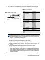
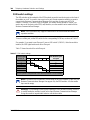
The CE Marking on this equipment indicates compliance with
the following:
This device conforms to Directive 1999/5/EC on Radio
Equipment and Telecommunications Terminal Equipment as
adopted by the European Parliament And Of The Council.
WARNING
This is a class A product. In a domestic environment this product may cause radio
interference in which case the user may be required to take adequate measures.
The above warning is inserted for regulatory reasons. If any customer believes that
they have an interference problem, either because their Nortel Networks product
seems to cause interference or suffers from interference, they should contact their
distributor immediately. The distributor will assist with a remedy for any problems
and, if necessary, will have full support from Nortel Networks.

12
P0993133 03
Safety
Additional Safety Information
The following interfaces are classified as Telecommunication Network Voltage (TNV) circuits, and may be
connected to exposed plant:
• DTM interface
• WAN interface
• TCM Isolator
The following interfaces are classified as Safety Extra Low Voltage (SELV) circuits, and shall not be
connected to exposed plant:
• BRIM Interface
• TCM extensions
• external music sources (MSCX)
• auxiliary ringer (AUX)
• paging system relay (PAGE)
WARNING!
Only qualified service personnel may install this equipment. The instructions in this
manual are intended for use by qualified service personnel only.
Risk of shock.
Ensure the Business Communications Manager is unplugged from the power socket
and that any telephone or network cables are unplugged before opening the
Business Communications Manager.
Read and follow installation instructions carefully
Only qualified persons should service the system.
The installation and service of this hardware is to be performed only by service
personnel having appropriate training and experience necessary to be aware of
hazards to which they are exposed in performing a task and of measures to minimize
the danger to themselves or other persons.
Electrical shock hazards from the telecommunication network and AC mains are
possible with this equipment. To minimize risk to service personnel and users, the
Business Communications Manager system must be connected to an outlet with a
third-wire Earth.
Service personnel must be alert to the possibility of high leakage currents becoming
available on metal system surfaces during power line fault events near network lines.
These leakage currents normally safely flow to Protective Earth via the power cord.
Therefore, it is mandatory that connection to an earthed outlet is performed first and
removed last when cabling to the unit. Specifically, operations requiring the unit to be
powered down must have the network connections (exchange lines) removed first.

13
Installation and Maintenance Guide
• serial port
• LAN interface
The following interfaces are classified as Telecommunication Network Voltage (TNV) circuits, and shall
NOT be connected to exposed plant:
•ATA II
Limited Warranty
Nortel Networks warrants this product against defects and malfunctions during a one (1) year period from the
date of original purchase. If there is a defect or malfunction, Nortel Networks shall, at its option, and as the
exclusive remedy, either repair or replace the telephone set at no charge, if returned within the warranty
period.
If replacement parts are used in making repairs, these parts may be refurbished, or may contain refurbished
materials. If it is necessary to replace the telephone set, it may be replaced with a refurbished telephone of the
same design and color. If it should become necessary to repair or replace a defective or malfunctioning
telephone set under this warranty, the provisions of this warranty shall apply to the repaired or replaced
telephone set until the expiration of ninety (90) days from the date of pick up, or the date of shipment to you,
of the repaired or replacement set, or until the end of the original warranty period, whichever is later. Proof
of the original purchase date is to be provided with all telephone sets returned for warranty repairs.
Exclusions
Nortel Networks does not warrant its telephone sets to be compatible with the equipment of any particular
telephone company. This warranty does not extend to damage to products resulting from improper installation
or operation, alteration, accident, neglect, abuse, misuse, fire or natural causes such as storms or floods, after
the telephone is in your possession.
Nortel Networks shall not be liable for any incidental or consequential damages, including, but not limited to,
loss, damage or expense directly or indirectly arising from the customers use of or inability to use this
telephone, either separately or in combination with other equipment. This paragraph, however, shall not apply
to consequential damages for injury to the person in the case of telephones used or bought for use primarily
for personal, family or household purposes.
This warranty sets forth the entire liability and obligations of Nortel Networks with respect to breach of
warranty, and the warranties set forth or limited herein are the sole warranties and are in lieu of all other
warranties, expressed or implied, including warranties or fitness for particular purpose and merchantability.
Warranty Repair Services
Should the set fail during the warranty period:
In North America, please call 1-800-574-1611 for further information.
Outside North America, contact your sales representative for return instructions. You will be responsible
for shipping charges, if any. When you return this telephone for warranty service, you must present proof of
purchase.

14
P0993133 03
After Warranty Service
Nortel Networks offers ongoing repair and support for this product. This service provides repair or
replacement of your Nortel Networks product, at Nortel Networks option, for a fixed charge. You are
responsible for all shipping charges. For further information and shipping instructions:
In North America, contact our service information number: 1-800-574-1611.
Outside North America, contact your sales representative.
Repairs to this product may be made only by the manufacturer and its authorized agents, or by others who are
legally authorized. This restriction applies during and after the warranty period. Unauthorized repair will void
the warranty.

15
Installation and Maintenance Guide
Contents
North American Regulatory Information . . . . . . . . . . . . . . . . . . . . . . . . . . . . . . . . . . . . 2
Safety . . . . . . . . . . . . . . . . . . . . . . . . . . . . . . . . . . . . . . . . . . . . . . . . . . . . . . . . . . . 2
Enhanced 911 Configuration . . . . . . . . . . . . . . . . . . . . . . . . . . . . . . . . . . . . . . . . . 3
Radio-frequency Interference . . . . . . . . . . . . . . . . . . . . . . . . . . . . . . . . . . . . . . . . . 3
Telecommunication Registration . . . . . . . . . . . . . . . . . . . . . . . . . . . . . . . . . . . . . . . 4
Network Connection . . . . . . . . . . . . . . . . . . . . . . . . . . . . . . . . . . . . . . . . . . . . . . . . 5
Hearing Aid Compatibility . . . . . . . . . . . . . . . . . . . . . . . . . . . . . . . . . . . . . . . . . . . . 5
Electromagnetic Compatibility . . . . . . . . . . . . . . . . . . . . . . . . . . . . . . . . . . . . . . . . . 5
Telephone Company Registration . . . . . . . . . . . . . . . . . . . . . . . . . . . . . . . . . . . . . . 5
Use of a Music Source . . . . . . . . . . . . . . . . . . . . . . . . . . . . . . . . . . . . . . . . . . . . . . 6
Rights of the Telecommunications Company . . . . . . . . . . . . . . . . . . . . . . . . . . . . . 6
Repairs . . . . . . . . . . . . . . . . . . . . . . . . . . . . . . . . . . . . . . . . . . . . . . . . . . . . . . . . . . 6
Canadian Regulations - please read carefully . . . . . . . . . . . . . . . . . . . . . . . . . . . . 6
US Regulations - please read carefully . . . . . . . . . . . . . . . . . . . . . . . . . . . . . . . . . . 7
Federal Communications Commission (FCC) Notice . . . . . . . . . . . . . . . . . . . . 7
EMI/EMC (FCC Part 15) . . . . . . . . . . . . . . . . . . . . . . . . . . . . . . . . . . . . . . . . . 9
Important Safety Instructions . . . . . . . . . . . . . . . . . . . . . . . . . . . . . . . . . . . . . . 9
International Regulatory Information . . . . . . . . . . . . . . . . . . . . . . . . . . . . . . . . . . . . . . 11
Safety . . . . . . . . . . . . . . . . . . . . . . . . . . . . . . . . . . . . . . . . . . . . . . . . . . . . . . . . . . 12
Additional Safety Information . . . . . . . . . . . . . . . . . . . . . . . . . . . . . . . . . . . . . . . . 12
Limited Warranty . . . . . . . . . . . . . . . . . . . . . . . . . . . . . . . . . . . . . . . . . . . . . . . . . . . . . 13
Exclusions . . . . . . . . . . . . . . . . . . . . . . . . . . . . . . . . . . . . . . . . . . . . . . . . . . . . . . . 13
Warranty Repair Services . . . . . . . . . . . . . . . . . . . . . . . . . . . . . . . . . . . . . . . . . . . 13
After Warranty Service . . . . . . . . . . . . . . . . . . . . . . . . . . . . . . . . . . . . . . . . . . . . . 14
Preface . . . . . . . . . . . . . . . . . . . . . . . . . . . . . . . . . . . . . . . . . . . . . . . . . . . . . . 33
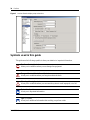
Display Tips . . . . . . . . . . . . . . . . . . . . . . . . . . . . . . . . . . . . . . . . . . . . . . . . . . . . . . . . . 33
Symbols used in this guide . . . . . . . . . . . . . . . . . . . . . . . . . . . . . . . . . . . . . . . . . . . . . 34
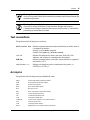
Text conventions . . . . . . . . . . . . . . . . . . . . . . . . . . . . . . . . . . . . . . . . . . . . . . . . . . . . . 35
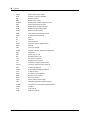
Acronyms . . . . . . . . . . . . . . . . . . . . . . . . . . . . . . . . . . . . . . . . . . . . . . . . . . . . . . . . . . . 35
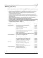
Related publications . . . . . . . . . . . . . . . . . . . . . . . . . . . . . . . . . . . . . . . . . . . . . . . . . . 37
How to Get Help . . . . . . . . . . . . . . . . . . . . . . . . . . . . . . . . . . . . . . . . . . . . . . . . . . . . . 38
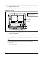
Chapter 1
Introduction to the Business Communications Manager
Platform Hardware . . . . . . . . . . . . . . . . . . . . . . . . . . . . . . . . . . . . . . . . . . . . . 39
Business Communications Manager Field Replaceable Units . . . . . . . . . . . . . . . . . . 40
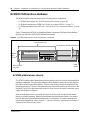
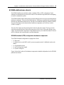
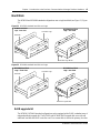
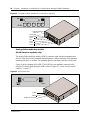
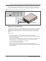
BCM200 Platform Base Hardware . . . . . . . . . . . . . . . . . . . . . . . . . . . . . . . . . . . . . . . 44
BCM200 platform base chassis . . . . . . . . . . . . . . . . . . . . . . . . . . . . . . . . . . . . . . 44
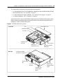
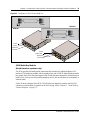
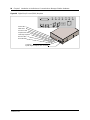
BCM400 Platform Base Hardware . . . . . . . . . . . . . . . . . . . . . . . . . . . . . . . . . . . . . . . 46

16 Contents
P0993133 03
BCM400 platform base chassis . . . . . . . . . . . . . . . . . . . . . . . . . . . . . . . . . . . . . . 47
BCM400 standard (STD) configuration hardware components . . . . . . . . . . . 47
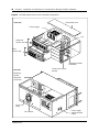
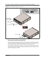
BCM400 platform redundant feature option (RFO) configuration . . . . . . . . . . 49
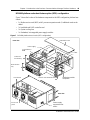
BCM400 advanced function tray (AFT) . . . . . . . . . . . . . . . . . . . . . . . . . . . . . . . . . 50
BCM400 advanced function tray RAID status LEDs . . . . . . . . . . . . . . . . . . . . 51
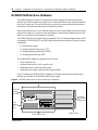
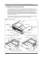
Platform Media Bay Module Bays and Backplane . . . . . . . . . . . . . . . . . . . . . . . . . . . . 51
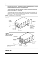
Base Function Tray Component Hardware . . . . . . . . . . . . . . . . . . . . . . . . . . . . . . . . . 54
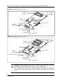
Base function tray chassis . . . . . . . . . . . . . . . . . . . . . . . . . . . . . . . . . . . . . . . . . . 54
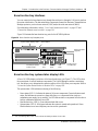
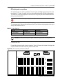
Base function tray interfaces . . . . . . . . . . . . . . . . . . . . . . . . . . . . . . . . . . . . . . . . . 55
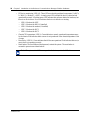
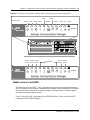
Base function tray system status display LEDs . . . . . . . . . . . . . . . . . . . . . . . . . . 55
Media services card (MSC) . . . . . . . . . . . . . . . . . . . . . . . . . . . . . . . . . . . . . . . . . . 57
MSC IP call processing hardware . . . . . . . . . . . . . . . . . . . . . . . . . . . . . . . . . . 59
Main card . . . . . . . . . . . . . . . . . . . . . . . . . . . . . . . . . . . . . . . . . . . . . . . . . . . . . . . 60
Main card connections . . . . . . . . . . . . . . . . . . . . . . . . . . . . . . . . . . . . . . . . . . 61
PCI riser card . . . . . . . . . . . . . . . . . . . . . . . . . . . . . . . . . . . . . . . . . . . . . . . . . 61
Data networking components . . . . . . . . . . . . . . . . . . . . . . . . . . . . . . . . . . . . . . . . 62
WAN interface card . . . . . . . . . . . . . . . . . . . . . . . . . . . . . . . . . . . . . . . . . . . . . 62
Modem card . . . . . . . . . . . . . . . . . . . . . . . . . . . . . . . . . . . . . . . . . . . . . . . . . . 63
I/O Interface card . . . . . . . . . . . . . . . . . . . . . . . . . . . . . . . . . . . . . . . . . . . . . . . . . . . . . 64
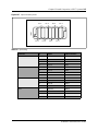
Platform Power Supply . . . . . . . . . . . . . . . . . . . . . . . . . . . . . . . . . . . . . . . . . . . . . . . . 65
BCM400 redundant power supply . . . . . . . . . . . . . . . . . . . . . . . . . . . . . . . . . . . . . 66
Hard Disk . . . . . . . . . . . . . . . . . . . . . . . . . . . . . . . . . . . . . . . . . . . . . . . . . . . . . . . . . . . 67
RAID upgrade kit . . . . . . . . . . . . . . . . . . . . . . . . . . . . . . . . . . . . . . . . . . . . . . . . . . 67
Cooling Fan . . . . . . . . . . . . . . . . . . . . . . . . . . . . . . . . . . . . . . . . . . . . . . . . . . . . . . . . . 68
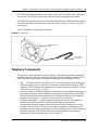
Telephony Components . . . . . . . . . . . . . . . . . . . . . . . . . . . . . . . . . . . . . . . . . . . . . . . . 69
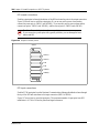
Media bay modules (MBMs) . . . . . . . . . . . . . . . . . . . . . . . . . . . . . . . . . . . . . . . . . 71
Media bay module LED indicators . . . . . . . . . . . . . . . . . . . . . . . . . . . . . . . . . . . . 73
Media bay module power connections . . . . . . . . . . . . . . . . . . . . . . . . . . . . . . . . . 73
Media bay module DIP switches . . . . . . . . . . . . . . . . . . . . . . . . . . . . . . . . . . . . . . 74
Trunk Media Bay Modules . . . . . . . . . . . . . . . . . . . . . . . . . . . . . . . . . . . . . . . . . . . 74
Digital trunk media bay module . . . . . . . . . . . . . . . . . . . . . . . . . . . . . . . . . . . 75
Caller ID trunk media bay module . . . . . . . . . . . . . . . . . . . . . . . . . . . . . . . . . 76
Basic rate interface media bay module . . . . . . . . . . . . . . . . . . . . . . . . . . . . . 77
Station Media Bay Modules . . . . . . . . . . . . . . . . . . . . . . . . . . . . . . . . . . . . . . . . . . 78
Digital station media bay module (DSM) . . . . . . . . . . . . . . . . . . . . . . . . . . . . 78
4X16 Media Bay Module . . . . . . . . . . . . . . . . . . . . . . . . . . . . . . . . . . . . . . . . 79
Analog station media bay module . . . . . . . . . . . . . . . . . . . . . . . . . . . . . . . . . . 80
Specialized Media Bay Modules . . . . . . . . . . . . . . . . . . . . . . . . . . . . . . . . . . . . . . 81
Digital enhanced cordless telecommunications (DECT)
media bay module . . . . . . . . . . . . . . . . . . . . . . . . . . . . . . . . . . . . . . . . . . . . 81
Fiber expansion media bay module (FEM) . . . . . . . . . . . . . . . . . . . . . . . . . . . 82
Digital Drop & Insert MUX (DDIM) . . . . . . . . . . . . . . . . . . . . . . . . . . . . . . . . . 83

Contents 17
Installation and Maintenance Guide
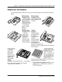
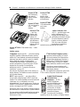
Telephones and adapters . . . . . . . . . . . . . . . . . . . . . . . . . . . . . . . . . . . . . . . . . . . . . . 85
Portable systems . . . . . . . . . . . . . . . . . . . . . . . . . . . . . . . . . . . . . . . . . . . . . . . . . . 87
Companion System Components . . . . . . . . . . . . . . . . . . . . . . . . . . . . . . . . . . 87
DECT System Components . . . . . . . . . . . . . . . . . . . . . . . . . . . . . . . . . . . . . . 88
T7406 system components . . . . . . . . . . . . . . . . . . . . . . . . . . . . . . . . . . . . . . . 88
NetVision system components . . . . . . . . . . . . . . . . . . . . . . . . . . . . . . . . . . . . 88
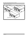
Business Communications Manager Expansion Unit . . . . . . . . . . . . . . . . . . . . . . . . . 90
Chapter 2
Auxilliary Requirements and Installation Process Overview. . . . . . . . . . . 91
Computer Specifications . . . . . . . . . . . . . . . . . . . . . . . . . . . . . . . . . . . . . . . . . . . . . . . 91
Browser Requirements . . . . . . . . . . . . . . . . . . . . . . . . . . . . . . . . . . . . . . . . . . . . . . . . 91
Preloading Java class Files On Your Workstation . . . . . . . . . . . . . . . . . . . . . . . . . 92
Optimizing Unified Manager Speed . . . . . . . . . . . . . . . . . . . . . . . . . . . . . . . . . . . 92
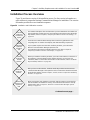
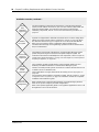
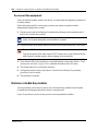
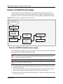
Installation Process Overview . . . . . . . . . . . . . . . . . . . . . . . . . . . . . . . . . . . . . . . . . . . 93
Installation Preparation Checklist . . . . . . . . . . . . . . . . . . . . . . . . . . . . . . . . . . . . . . . . 95
Environment Checklist . . . . . . . . . . . . . . . . . . . . . . . . . . . . . . . . . . . . . . . . . . . . . 95
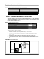
Electrical Requirements . . . . . . . . . . . . . . . . . . . . . . . . . . . . . . . . . . . . . . . . . . . . 95
Internal Wiring Requirements . . . . . . . . . . . . . . . . . . . . . . . . . . . . . . . . . . . . . . . . 96
Digital Loop . . . . . . . . . . . . . . . . . . . . . . . . . . . . . . . . . . . . . . . . . . . . . . . . . . . 96
Analog Loop . . . . . . . . . . . . . . . . . . . . . . . . . . . . . . . . . . . . . . . . . . . . . . . . . . 96
System Equipment and Supplies . . . . . . . . . . . . . . . . . . . . . . . . . . . . . . . . . . . . . . . . . 97
Basic hardware . . . . . . . . . . . . . . . . . . . . . . . . . . . . . . . . . . . . . . . . . . . . . . . . . . . 97
Optional equipment . . . . . . . . . . . . . . . . . . . . . . . . . . . . . . . . . . . . . . . . . . . . . . . . 97
Companion equipment . . . . . . . . . . . . . . . . . . . . . . . . . . . . . . . . . . . . . . . . . . . . . 98
Optional Companion equipment . . . . . . . . . . . . . . . . . . . . . . . . . . . . . . . . . . . 98
Other cordless systems . . . . . . . . . . . . . . . . . . . . . . . . . . . . . . . . . . . . . . . . . 98
DECT Equipment . . . . . . . . . . . . . . . . . . . . . . . . . . . . . . . . . . . . . . . . . . . . . . . . . 98
Equipment for installing the platform base chassis . . . . . . . . . . . . . . . . . . . . . . . . 98
C3050 CT2 Plus (Canada) . . . . . . . . . . . . . . . . . . . . . . . . . . . . . . . . . . . . . . . 98
C3050 Etiquette (USA) . . . . . . . . . . . . . . . . . . . . . . . . . . . . . . . . . . . . . . . . . . 98
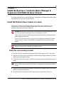
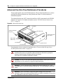
Chapter 3
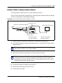
Install the Business Communications Manager & Expansion Unit
Platform Base Chassis . . . . . . . . . . . . . . . . . . . . . . . . . . . . . . . . . . . . . . . . . 99
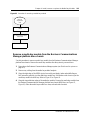
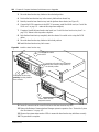
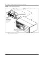
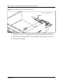
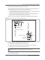
Install the Platform Base Chassis in a Rack . . . . . . . . . . . . . . . . . . . . . . . . . . . . . . . . 99
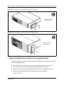
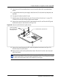
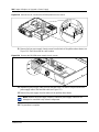
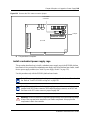
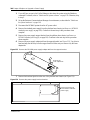
Attach the rack mounting brackets . . . . . . . . . . . . . . . . . . . . . . . . . . . . . . . . . . . . 99
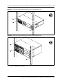
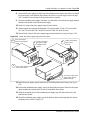
Mount the platform base chassis into an equipment rack . . . . . . . . . . . . . . . . . . 100
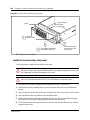
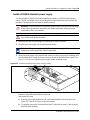
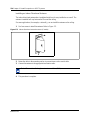
Install the Platform Base Chassis on the Wall . . . . . . . . . . . . . . . . . . . . . . . . . . . . . . 102
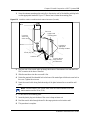
Install the Platform Base Chassis on a Flat Surface . . . . . . . . . . . . . . . . . . . . . . . . . 104
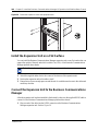
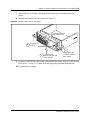
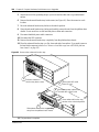
Install the Expansion Unit into a Rack . . . . . . . . . . . . . . . . . . . . . . . . . . . . . . . . . . . . 104
Attach the mounting brackets to the Expansion Unit . . . . . . . . . . . . . . . . . . . . . . 104

18 Contents
P0993133 03
Mount the Expansion Unit to the rack . . . . . . . . . . . . . . . . . . . . . . . . . . . . . . . . . 105
Install the Expansion Unit on a Flat Surface . . . . . . . . . . . . . . . . . . . . . . . . . . . . . . . 106
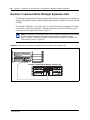
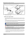
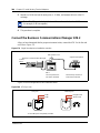
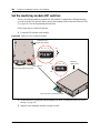
Connect the Expansion Unit to the Business Communications Manager . . . . . . . . . 106
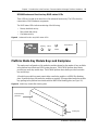
Chapter 4
Install, remove or replace the Media Bay Modules. . . . . . . . . . . . . . . . . . 109
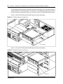
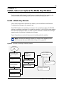
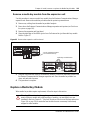
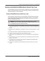
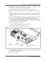
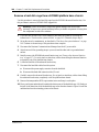
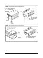
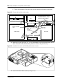
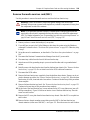
Install a Media Bay Module . . . . . . . . . . . . . . . . . . . . . . . . . . . . . . . . . . . . . . . . . . . . 109
Shut down the system . . . . . . . . . . . . . . . . . . . . . . . . . . . . . . . . . . . . . . . . . . . . . 110
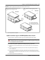
Install a media bay module in the Business Communications Manager
platform base chassis . . . . . . . . . . . . . . . . . . . . . . . . . . . . . . . . . . . . . . . . . . . 111
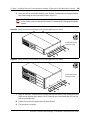
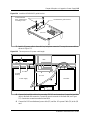
Install a media bay module in the expansion unit . . . . . . . . . . . . . . . . . . . . . . . . 111
Reconnect the equipment . . . . . . . . . . . . . . . . . . . . . . . . . . . . . . . . . . . . . . . . . . 112
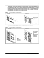
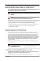
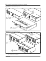
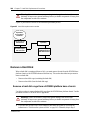
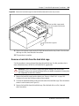
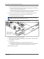
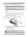
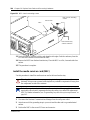
Remove a media bay module . . . . . . . . . . . . . . . . . . . . . . . . . . . . . . . . . . . . . . . . . . 112
Remove a media bay module from the Business Communications Manager
platform base chassis . . . . . . . . . . . . . . . . . . . . . . . . . . . . . . . . . . . . . . . . . . . 113
Remove a media bay module from the expansion unit . . . . . . . . . . . . . . . . . . . . 115
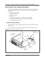
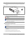
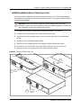
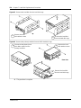
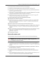
Replace a Media Bay Module . . . . . . . . . . . . . . . . . . . . . . . . . . . . . . . . . . . . . . . . . . 115
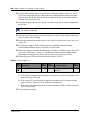
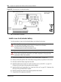
Wire the Media Bay Modules . . . . . . . . . . . . . . . . . . . . . . . . . . . . . . . . . . . . . . . . . . . 117
Module Wiring Warnings . . . . . . . . . . . . . . . . . . . . . . . . . . . . . . . . . . . . . . . . . . . . . . 118
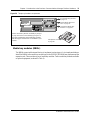
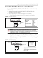
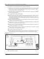
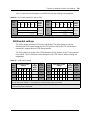
Connect the Media Bay Modules to Service Providers . . . . . . . . . . . . . . . . . . . . . . . 119
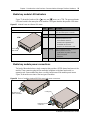
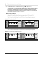
Wire Media Bay Modules to Internal Connections . . . . . . . . . . . . . . . . . . . . . . . . . . . 121
FEM Wiring . . . . . . . . . . . . . . . . . . . . . . . . . . . . . . . . . . . . . . . . . . . . . . . . . . . . . . . . 124
Connect the fiber cables . . . . . . . . . . . . . . . . . . . . . . . . . . . . . . . . . . . . . . . . . . . 125
Installation/Replacement Troubleshooting . . . . . . . . . . . . . . . . . . . . . . . . . . . . . . . . . 126
Chapter 5
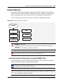
Business Communications Manager System Startup . . . . . . . . . . . . . . . 127
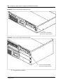
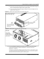
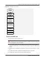
Check Power and Wiring . . . . . . . . . . . . . . . . . . . . . . . . . . . . . . . . . . . . . . . . . . . . . . 128
Check system power and status . . . . . . . . . . . . . . . . . . . . . . . . . . . . . . . . . . . . . 129
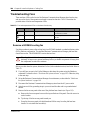
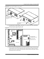
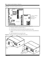
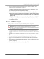
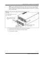
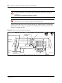
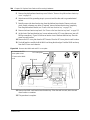
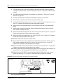
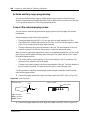
Connect the Data Networking Hardware . . . . . . . . . . . . . . . . . . . . . . . . . . . . . . . . . . 131
Connect the cards . . . . . . . . . . . . . . . . . . . . . . . . . . . . . . . . . . . . . . . . . . . . . . . . 132
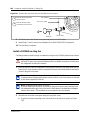
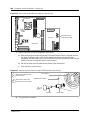
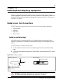
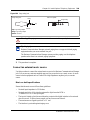
Connect wiring to the WAN card . . . . . . . . . . . . . . . . . . . . . . . . . . . . . . . . . . 133
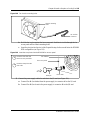
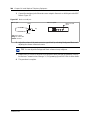
Connect wiring to the modem . . . . . . . . . . . . . . . . . . . . . . . . . . . . . . . . . . . . 134
Install the cards . . . . . . . . . . . . . . . . . . . . . . . . . . . . . . . . . . . . . . . . . . . . . . . . . . 136
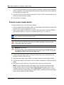
Initialize the System . . . . . . . . . . . . . . . . . . . . . . . . . . . . . . . . . . . . . . . . . . . . . . . . . . 136
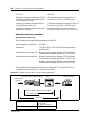
Data parameter requirements . . . . . . . . . . . . . . . . . . . . . . . . . . . . . . . . . . . . . . . 136
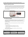
Default IP settings . . . . . . . . . . . . . . . . . . . . . . . . . . . . . . . . . . . . . . . . . . . . . . . . 136
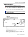
Connecting when there is an IP address conflict . . . . . . . . . . . . . . . . . . . . . . . . 137
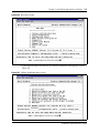
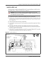
Use of a null modem serial cable . . . . . . . . . . . . . . . . . . . . . . . . . . . . . . . . . 137
Null modem cable setup . . . . . . . . . . . . . . . . . . . . . . . . . . . . . . . . . . . . . . . . 138
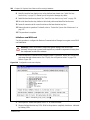
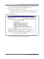
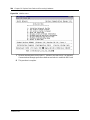
Display the configuration menus . . . . . . . . . . . . . . . . . . . . . . . . . . . . . . . . . 139
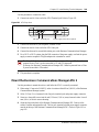
Ethernet crossover cable usage . . . . . . . . . . . . . . . . . . . . . . . . . . . . . . . . . . . . . 140
Set the crossover connections . . . . . . . . . . . . . . . . . . . . . . . . . . . . . . . . . . . 140

Contents 19
Installation and Maintenance Guide
Configure your computer . . . . . . . . . . . . . . . . . . . . . . . . . . . . . . . . . . . . . . . 141
Connect the Ethernet crossover cable . . . . . . . . . . . . . . . . . . . . . . . . . . . . . 141
Enter the software keycodes . . . . . . . . . . . . . . . . . . . . . . . . . . . . . . . . . . . . . . . . . . . 142
Regenerating keycodes after system replacement . . . . . . . . . . . . . . . . . . . . . . . 142
Chapter 6
Prepare Hardware for Maintenance or Upgrades . . . . . . . . . . . . . . . . . . . 143
Precautions . . . . . . . . . . . . . . . . . . . . . . . . . . . . . . . . . . . . . . . . . . . . . . . . . . . . . . . . 143
Special Tools . . . . . . . . . . . . . . . . . . . . . . . . . . . . . . . . . . . . . . . . . . . . . . . . . . . . . . . 145
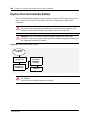
Controlled System Shutdown . . . . . . . . . . . . . . . . . . . . . . . . . . . . . . . . . . . . . . . . . . 145
Shut down the system software . . . . . . . . . . . . . . . . . . . . . . . . . . . . . . . . . . . . . 145
Shut down the system hardware . . . . . . . . . . . . . . . . . . . . . . . . . . . . . . . . . . . . . 146
Restart the System after Maintenance . . . . . . . . . . . . . . . . . . . . . . . . . . . . . . . . . . . 147
Restore the System to Operation . . . . . . . . . . . . . . . . . . . . . . . . . . . . . . . . . . . . 147
Software Restart . . . . . . . . . . . . . . . . . . . . . . . . . . . . . . . . . . . . . . . . . . . . . . . . . 147
Base Function Tray Maintenance Procedures . . . . . . . . . . . . . . . . . . . . . . . . . . . . . . 148
Remove the base function tray . . . . . . . . . . . . . . . . . . . . . . . . . . . . . . . . . . . . . . 150
Install the base function tray . . . . . . . . . . . . . . . . . . . . . . . . . . . . . . . . . . . . . . . . 151
Remove the base function tray bezel . . . . . . . . . . . . . . . . . . . . . . . . . . . . . . . . . 153
Install the base function tray bezel . . . . . . . . . . . . . . . . . . . . . . . . . . . . . . . . . . . 154
Advanced Function Tray Maintenance Procedures . . . . . . . . . . . . . . . . . . . . . . . . . . 156
Remove the advanced function tray . . . . . . . . . . . . . . . . . . . . . . . . . . . . . . . . . . 157
Install the advanced function tray . . . . . . . . . . . . . . . . . . . . . . . . . . . . . . . . . . . . 159
Remove and Install the Platform Base Chassis Top Cover . . . . . . . . . . . . . . . . . . . . 161
Remove the platform base chassis top cover . . . . . . . . . . . . . . . . . . . . . . . . . . . 161
Install the platform base chassis top cover . . . . . . . . . . . . . . . . . . . . . . . . . . . . . 163
Chapter 7
Hard Disk Replacement Procedures . . . . . . . . . . . . . . . . . . . . . . . . . . . . . 165
Remove a Hard Disk . . . . . . . . . . . . . . . . . . . . . . . . . . . . . . . . . . . . . . . . . . . . . . . . . 166
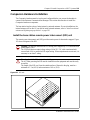
Remove a hard disk cage from a BCM200 platform base chassis . . . . . . . . . . . 166
Remove a hard disk cage from a BCM400 platform base chassis . . . . . . . . . . . 168
Remove a hard disk from the hard disk cage . . . . . . . . . . . . . . . . . . . . . . . . . . . 169
Install a New Hard Disk . . . . . . . . . . . . . . . . . . . . . . . . . . . . . . . . . . . . . . . . . . . . . . . 171
Install a hard disk into a hard disk cage . . . . . . . . . . . . . . . . . . . . . . . . . . . . . . . 171
Install a hard disk cage in a BCM200 platform base chassis . . . . . . . . . . . . . . . 173
Install a hard disk cage in a BCM400 platform base chassis . . . . . . . . . . . . . . . 175
Initialize the Hard Disk . . . . . . . . . . . . . . . . . . . . . . . . . . . . . . . . . . . . . . . . . . . . . . . . 176
Chapter 8
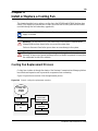
Install or Replace a Cooling Fan. . . . . . . . . . . . . . . . . . . . . . . . . . . . . . . . . 179
Cooling Fan Replacement Process . . . . . . . . . . . . . . . . . . . . . . . . . . . . . . . . . . . . . . 179

20 Contents
P0993133 03
Troubleshooting Fans . . . . . . . . . . . . . . . . . . . . . . . . . . . . . . . . . . . . . . . . . . . . . . . . 180
Remove a BCM400 cooling fan . . . . . . . . . . . . . . . . . . . . . . . . . . . . . . . . . . . . . 180
Install a BCM400 cooling fan . . . . . . . . . . . . . . . . . . . . . . . . . . . . . . . . . . . . . . . 182
Remove a BCM200 cooling fan . . . . . . . . . . . . . . . . . . . . . . . . . . . . . . . . . . . . . 185
Install the BCM200 cooling fan . . . . . . . . . . . . . . . . . . . . . . . . . . . . . . . . . . . . . . 187
Remove an expansion unit fan . . . . . . . . . . . . . . . . . . . . . . . . . . . . . . . . . . . . . . 188
Install an expansion unit fan . . . . . . . . . . . . . . . . . . . . . . . . . . . . . . . . . . . . . . . . 190
Chapter 9
Replace or Upgrade a Power Supply . . . . . . . . . . . . . . . . . . . . . . . . . . . . . 191
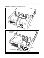
Replace a Standard Power Supply . . . . . . . . . . . . . . . . . . . . . . . . . . . . . . . . . . . . . . 192
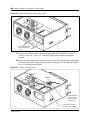
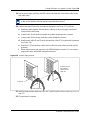
Remove a BCM200 standard power supply . . . . . . . . . . . . . . . . . . . . . . . . . . . . 192
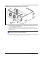
Install a BCM200 standard power supply . . . . . . . . . . . . . . . . . . . . . . . . . . . . . . 195
Remove a BCM400 standard power supply . . . . . . . . . . . . . . . . . . . . . . . . . . . . 199
Install a BCM400 standard power supply . . . . . . . . . . . . . . . . . . . . . . . . . . . . . . 201
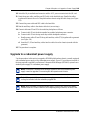
Upgrade to a redundant power supply . . . . . . . . . . . . . . . . . . . . . . . . . . . . . . . . . . . 203
Remove the PSU status connector jumper . . . . . . . . . . . . . . . . . . . . . . . . . . . . . 204
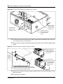
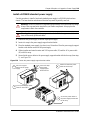
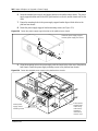
Install a redundant power supply cage . . . . . . . . . . . . . . . . . . . . . . . . . . . . . . . . 205
Remove a BCM400 redundant power supply cage . . . . . . . . . . . . . . . . . . . . . . . 210
Install a power supply module . . . . . . . . . . . . . . . . . . . . . . . . . . . . . . . . . . . . . . . 212
Remove a power supply module . . . . . . . . . . . . . . . . . . . . . . . . . . . . . . . . . . . . . 214
Chapter 10
Replace Data Cards and Processing Hardware . . . . . . . . . . . . . . . . . . . . 217
System status LEDs . . . . . . . . . . . . . . . . . . . . . . . . . . . . . . . . . . . . . . . . . . . . . . . . . 217
Card Replacement Procedures . . . . . . . . . . . . . . . . . . . . . . . . . . . . . . . . . . . . . . . . . 217
Remove the WAN card . . . . . . . . . . . . . . . . . . . . . . . . . . . . . . . . . . . . . . . . . . . . 219
Install the WAN card . . . . . . . . . . . . . . . . . . . . . . . . . . . . . . . . . . . . . . . . . . . . . . 221
Initialize a new WAN card . . . . . . . . . . . . . . . . . . . . . . . . . . . . . . . . . . . . . . . 222
Remove the media services card (MSC) . . . . . . . . . . . . . . . . . . . . . . . . . . . . . . 225
Install the media services card (MSC) . . . . . . . . . . . . . . . . . . . . . . . . . . . . . . . . 226
Install the modem card . . . . . . . . . . . . . . . . . . . . . . . . . . . . . . . . . . . . . . . . . . . . 229
Replace the Processor Expansion Card (PEC) . . . . . . . . . . . . . . . . . . . . . . . . . . . . . 230
Remove the processor expansion card (PEC) . . . . . . . . . . . . . . . . . . . . . . . . . . 231
Install a processor expansion card (PEC) . . . . . . . . . . . . . . . . . . . . . . . . . . . . . . 233
Replace Memory . . . . . . . . . . . . . . . . . . . . . . . . . . . . . . . . . . . . . . . . . . . . . . . . . . . . 235
Remove the dual in-line memory module (DIMM) card . . . . . . . . . . . . . . . . . . . . 235
Install the dual in-line memory module (DIMM) card . . . . . . . . . . . . . . . . . . . . . . 237
Replace the Clock/Calendar Battery . . . . . . . . . . . . . . . . . . . . . . . . . . . . . . . . . . . . . 238
Remove the clock/calendar battery . . . . . . . . . . . . . . . . . . . . . . . . . . . . . . . . . . . 239
Install a new clock/calendar battery . . . . . . . . . . . . . . . . . . . . . . . . . . . . . . . . . . 240
Page is loading ...
Page is loading ...
Page is loading ...
Page is loading ...
Page is loading ...
Page is loading ...
Page is loading ...
Page is loading ...
Page is loading ...
Page is loading ...
Page is loading ...
Page is loading ...
Page is loading ...
Page is loading ...
Page is loading ...
Page is loading ...
Page is loading ...
Page is loading ...
Page is loading ...
Page is loading ...
Page is loading ...
Page is loading ...
Page is loading ...
Page is loading ...
Page is loading ...
Page is loading ...
Page is loading ...
Page is loading ...
Page is loading ...
Page is loading ...
Page is loading ...
Page is loading ...
Page is loading ...
Page is loading ...
Page is loading ...
Page is loading ...
Page is loading ...
Page is loading ...
Page is loading ...
Page is loading ...
Page is loading ...
Page is loading ...
Page is loading ...
Page is loading ...
Page is loading ...
Page is loading ...
Page is loading ...
Page is loading ...
Page is loading ...
Page is loading ...
Page is loading ...
Page is loading ...
Page is loading ...
Page is loading ...
Page is loading ...
Page is loading ...
Page is loading ...
Page is loading ...
Page is loading ...
Page is loading ...
Page is loading ...
Page is loading ...
Page is loading ...
Page is loading ...
Page is loading ...
Page is loading ...
Page is loading ...
Page is loading ...
Page is loading ...
Page is loading ...
Page is loading ...
Page is loading ...
Page is loading ...
Page is loading ...
Page is loading ...
Page is loading ...
Page is loading ...
Page is loading ...
Page is loading ...
Page is loading ...
Page is loading ...
Page is loading ...
Page is loading ...
Page is loading ...
Page is loading ...
Page is loading ...
Page is loading ...
Page is loading ...
Page is loading ...
Page is loading ...
Page is loading ...
Page is loading ...
Page is loading ...
Page is loading ...
Page is loading ...
Page is loading ...
Page is loading ...
Page is loading ...
Page is loading ...
Page is loading ...
Page is loading ...
Page is loading ...
Page is loading ...
Page is loading ...
Page is loading ...
Page is loading ...
Page is loading ...
Page is loading ...
Page is loading ...
Page is loading ...
Page is loading ...
Page is loading ...
Page is loading ...
Page is loading ...
Page is loading ...
Page is loading ...
Page is loading ...
Page is loading ...
Page is loading ...
Page is loading ...
Page is loading ...
Page is loading ...
Page is loading ...
Page is loading ...
Page is loading ...
Page is loading ...
Page is loading ...
Page is loading ...
Page is loading ...
Page is loading ...
Page is loading ...
Page is loading ...
Page is loading ...
Page is loading ...
Page is loading ...
Page is loading ...
Page is loading ...
Page is loading ...
Page is loading ...
Page is loading ...
Page is loading ...
Page is loading ...
Page is loading ...
Page is loading ...
Page is loading ...
Page is loading ...
Page is loading ...
Page is loading ...
Page is loading ...
Page is loading ...
Page is loading ...
Page is loading ...
Page is loading ...
Page is loading ...
Page is loading ...
Page is loading ...
Page is loading ...
Page is loading ...
Page is loading ...
Page is loading ...
Page is loading ...
Page is loading ...
Page is loading ...
Page is loading ...
Page is loading ...
Page is loading ...
Page is loading ...
Page is loading ...
Page is loading ...
Page is loading ...
Page is loading ...
Page is loading ...
Page is loading ...
Page is loading ...
Page is loading ...
Page is loading ...
Page is loading ...
Page is loading ...
Page is loading ...
Page is loading ...
Page is loading ...
Page is loading ...
Page is loading ...
Page is loading ...
Page is loading ...
Page is loading ...
Page is loading ...
Page is loading ...
Page is loading ...
Page is loading ...
Page is loading ...
Page is loading ...
Page is loading ...
Page is loading ...
Page is loading ...
Page is loading ...
Page is loading ...
Page is loading ...
Page is loading ...
Page is loading ...
Page is loading ...
Page is loading ...
Page is loading ...
Page is loading ...
Page is loading ...
Page is loading ...
Page is loading ...
Page is loading ...
Page is loading ...
Page is loading ...
Page is loading ...
Page is loading ...
Page is loading ...
Page is loading ...
Page is loading ...
Page is loading ...
Page is loading ...
Page is loading ...
Page is loading ...
Page is loading ...
Page is loading ...
Page is loading ...
Page is loading ...
Page is loading ...
Page is loading ...
Page is loading ...
Page is loading ...
Page is loading ...
Page is loading ...
Page is loading ...
Page is loading ...
Page is loading ...
Page is loading ...
Page is loading ...
Page is loading ...
Page is loading ...
Page is loading ...
Page is loading ...
Page is loading ...
Page is loading ...
Page is loading ...
Page is loading ...
Page is loading ...
Page is loading ...
Page is loading ...
Page is loading ...
Page is loading ...
Page is loading ...
Page is loading ...
Page is loading ...
Page is loading ...
Page is loading ...
Page is loading ...
Page is loading ...
Page is loading ...
Page is loading ...
Page is loading ...
Page is loading ...
Page is loading ...
Page is loading ...
Page is loading ...
Page is loading ...
Page is loading ...
Page is loading ...
Page is loading ...
Page is loading ...
Page is loading ...
Page is loading ...
Page is loading ...
Page is loading ...
Page is loading ...
Page is loading ...
Page is loading ...
Page is loading ...
Page is loading ...
Page is loading ...
Page is loading ...
Page is loading ...
Page is loading ...
Page is loading ...
Page is loading ...
Page is loading ...
Page is loading ...
Page is loading ...
Page is loading ...
Page is loading ...
Page is loading ...
Page is loading ...
Page is loading ...
Page is loading ...
Page is loading ...
Page is loading ...
Page is loading ...
Page is loading ...
Page is loading ...
Page is loading ...
Page is loading ...
Page is loading ...
Page is loading ...
Page is loading ...
Page is loading ...
Page is loading ...
Page is loading ...
Page is loading ...
Page is loading ...
Page is loading ...
Page is loading ...
Page is loading ...
Page is loading ...
Page is loading ...
Page is loading ...
Page is loading ...
Page is loading ...
Page is loading ...
Page is loading ...
Page is loading ...
Page is loading ...
Page is loading ...
Page is loading ...
Page is loading ...
Page is loading ...
Page is loading ...
Page is loading ...
Page is loading ...
Page is loading ...
Page is loading ...
Page is loading ...
Page is loading ...
Page is loading ...
Page is loading ...
Page is loading ...
Page is loading ...
Page is loading ...
Page is loading ...
Page is loading ...
Page is loading ...
Page is loading ...
Page is loading ...
Page is loading ...
Page is loading ...
Page is loading ...
Page is loading ...
Page is loading ...
Page is loading ...
Page is loading ...
Page is loading ...
Page is loading ...
Page is loading ...
Page is loading ...
Page is loading ...
Page is loading ...
Page is loading ...
Page is loading ...
Page is loading ...
-
 1
1
-
 2
2
-
 3
3
-
 4
4
-
 5
5
-
 6
6
-
 7
7
-
 8
8
-
 9
9
-
 10
10
-
 11
11
-
 12
12
-
 13
13
-
 14
14
-
 15
15
-
 16
16
-
 17
17
-
 18
18
-
 19
19
-
 20
20
-
 21
21
-
 22
22
-
 23
23
-
 24
24
-
 25
25
-
 26
26
-
 27
27
-
 28
28
-
 29
29
-
 30
30
-
 31
31
-
 32
32
-
 33
33
-
 34
34
-
 35
35
-
 36
36
-
 37
37
-
 38
38
-
 39
39
-
 40
40
-
 41
41
-
 42
42
-
 43
43
-
 44
44
-
 45
45
-
 46
46
-
 47
47
-
 48
48
-
 49
49
-
 50
50
-
 51
51
-
 52
52
-
 53
53
-
 54
54
-
 55
55
-
 56
56
-
 57
57
-
 58
58
-
 59
59
-
 60
60
-
 61
61
-
 62
62
-
 63
63
-
 64
64
-
 65
65
-
 66
66
-
 67
67
-
 68
68
-
 69
69
-
 70
70
-
 71
71
-
 72
72
-
 73
73
-
 74
74
-
 75
75
-
 76
76
-
 77
77
-
 78
78
-
 79
79
-
 80
80
-
 81
81
-
 82
82
-
 83
83
-
 84
84
-
 85
85
-
 86
86
-
 87
87
-
 88
88
-
 89
89
-
 90
90
-
 91
91
-
 92
92
-
 93
93
-
 94
94
-
 95
95
-
 96
96
-
 97
97
-
 98
98
-
 99
99
-
 100
100
-
 101
101
-
 102
102
-
 103
103
-
 104
104
-
 105
105
-
 106
106
-
 107
107
-
 108
108
-
 109
109
-
 110
110
-
 111
111
-
 112
112
-
 113
113
-
 114
114
-
 115
115
-
 116
116
-
 117
117
-
 118
118
-
 119
119
-
 120
120
-
 121
121
-
 122
122
-
 123
123
-
 124
124
-
 125
125
-
 126
126
-
 127
127
-
 128
128
-
 129
129
-
 130
130
-
 131
131
-
 132
132
-
 133
133
-
 134
134
-
 135
135
-
 136
136
-
 137
137
-
 138
138
-
 139
139
-
 140
140
-
 141
141
-
 142
142
-
 143
143
-
 144
144
-
 145
145
-
 146
146
-
 147
147
-
 148
148
-
 149
149
-
 150
150
-
 151
151
-
 152
152
-
 153
153
-
 154
154
-
 155
155
-
 156
156
-
 157
157
-
 158
158
-
 159
159
-
 160
160
-
 161
161
-
 162
162
-
 163
163
-
 164
164
-
 165
165
-
 166
166
-
 167
167
-
 168
168
-
 169
169
-
 170
170
-
 171
171
-
 172
172
-
 173
173
-
 174
174
-
 175
175
-
 176
176
-
 177
177
-
 178
178
-
 179
179
-
 180
180
-
 181
181
-
 182
182
-
 183
183
-
 184
184
-
 185
185
-
 186
186
-
 187
187
-
 188
188
-
 189
189
-
 190
190
-
 191
191
-
 192
192
-
 193
193
-
 194
194
-
 195
195
-
 196
196
-
 197
197
-
 198
198
-
 199
199
-
 200
200
-
 201
201
-
 202
202
-
 203
203
-
 204
204
-
 205
205
-
 206
206
-
 207
207
-
 208
208
-
 209
209
-
 210
210
-
 211
211
-
 212
212
-
 213
213
-
 214
214
-
 215
215
-
 216
216
-
 217
217
-
 218
218
-
 219
219
-
 220
220
-
 221
221
-
 222
222
-
 223
223
-
 224
224
-
 225
225
-
 226
226
-
 227
227
-
 228
228
-
 229
229
-
 230
230
-
 231
231
-
 232
232
-
 233
233
-
 234
234
-
 235
235
-
 236
236
-
 237
237
-
 238
238
-
 239
239
-
 240
240
-
 241
241
-
 242
242
-
 243
243
-
 244
244
-
 245
245
-
 246
246
-
 247
247
-
 248
248
-
 249
249
-
 250
250
-
 251
251
-
 252
252
-
 253
253
-
 254
254
-
 255
255
-
 256
256
-
 257
257
-
 258
258
-
 259
259
-
 260
260
-
 261
261
-
 262
262
-
 263
263
-
 264
264
-
 265
265
-
 266
266
-
 267
267
-
 268
268
-
 269
269
-
 270
270
-
 271
271
-
 272
272
-
 273
273
-
 274
274
-
 275
275
-
 276
276
-
 277
277
-
 278
278
-
 279
279
-
 280
280
-
 281
281
-
 282
282
-
 283
283
-
 284
284
-
 285
285
-
 286
286
-
 287
287
-
 288
288
-
 289
289
-
 290
290
-
 291
291
-
 292
292
-
 293
293
-
 294
294
-
 295
295
-
 296
296
-
 297
297
-
 298
298
-
 299
299
-
 300
300
-
 301
301
-
 302
302
-
 303
303
-
 304
304
-
 305
305
-
 306
306
-
 307
307
-
 308
308
-
 309
309
-
 310
310
-
 311
311
-
 312
312
-
 313
313
-
 314
314
-
 315
315
-
 316
316
-
 317
317
-
 318
318
-
 319
319
-
 320
320
-
 321
321
-
 322
322
-
 323
323
-
 324
324
-
 325
325
-
 326
326
-
 327
327
-
 328
328
-
 329
329
-
 330
330
-
 331
331
-
 332
332
-
 333
333
-
 334
334
-
 335
335
-
 336
336
-
 337
337
-
 338
338
-
 339
339
-
 340
340
-
 341
341
-
 342
342
-
 343
343
-
 344
344
-
 345
345
-
 346
346
-
 347
347
-
 348
348
-
 349
349
-
 350
350
-
 351
351
-
 352
352
-
 353
353
-
 354
354
-
 355
355
-
 356
356
-
 357
357
-
 358
358
-
 359
359
-
 360
360
-
 361
361
-
 362
362
-
 363
363
-
 364
364
-
 365
365
-
 366
366
-
 367
367
-
 368
368
-
 369
369
-
 370
370
-
 371
371
-
 372
372
-
 373
373
-
 374
374


Ask a question and I''ll find the answer in the document
Finding information in a document is now easier with AI
Related papers
-
Avaya BCM200/400 Installation and Maintenance Manual
-
-
-
-
-
-
-
-
-
Other documents
-
Nortel Networks BCM1000 User manual
-
 Commercial Electric 217F WH User manual
-
-
-
RCA RC 930 User manual
-
APC Replacement Battery Cartridge #22 User manual
-
Nortel Norstar Audio Conferencing Unit Installation guide
-
Juniper JCS 1200 Removing Manual
-
Arris TM602G Installation And Replacement
-
Nortel BCM50 Owner's manual
