Page is loading ...

LT
25
INSTRUCTION MANUAL
Scan for easy install video
http://san.us/630
We’ll Make It Stress-Free
If you have any questions along the way, just give us a call.
1-800-359-5520. We’re ready to help!

2
IMPORTANT SAFETY INSTRUCTIONS – SAVE THESE INSTRUCTIONS – PLEASE READ ENTIRE MANUAL PRIOR TO USE
No
—
Perfect!
Yes
—
This mount is NOT compatible. Visit MountFinder.Sanus.com or call
1-800-359-5520 (UK: 0800-056-2853) to fi nd a compatible mount.
Please read through these instructions completely to be sure you’re comfortable with this easy install process.
Also check your TV owner’s manual to see if there are any special requirements for mounting your TV.
If you do not understand these instructions or have doubts about the safety of the installation, assembly or use
of this product, contact Customer Service at 1-800-359-5520 (UK: 0800-056-2853).
Do you have
all the tools
needed?
Before getting started, let’s make sure this mount is perfect for you!
1
2
3
4
What is your
wall made of?
Unsure?
Drywall with
wood studs?
Solid concrete or
concrete block?
175 lb
(79.4 kg)
CAUTION: Avoid potential personal injuries and property damage!
● This product includes directions and hardware for use with wood stud, solid concrete and concrete block walls –
DO NOT install into drywall alone.
● The wall must be capable of supporting fi ve times the weight of the TV and mount combined.
● Do not use this product for any purpose not explicitly specifi ed by manufacturer.
● Manufacturer is not responsible for damage or injury caused by incorrect assembly or use.
Call Customer Service:
1-800-359-5520 (UK: 0800-056-2853)
Perfect! Perfect!
Ready to
begin?
Does your TV weigh
more than 175 lb
(79.4 kg) including
accessories?
1/2 in.
(13 mm)
3/16 in.
(5 mm)
Wood
Screwdriver Tape Measure Drill Bit Drill Bit Electric Drill Hammer Socket Wrench
1/2 in.
(13 mm)
Concrete
CAUTION:
DO NOT install
into drywall alone
Awl Pencil Level
Stud Finder

3
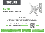
27.541
MAX.
699.53
17.323
440.00
18.220
462.79
1.503
MIN.
38.18
2.000
50.80
0.506
12.86
2.000
50.80
8.635
219.34
12.166
309.02
30.006
762.16
3.098
78.69
8°
MAX TILT UP
10°
MAX TILT DOWN
NOTE:
MAX. HEIGHT ADJUST
.5 IN.
in.
[mm]
Dimensions

4
M8 x 25mm
M8 x 45mm
M8 x 60mm
M6 x 25mm
M6 x 40mm
M6 x 55mm
M5 x 20mm
M5 x 30mm
M5 x 40mm
M4 x 20mm
M4 x 30mm
M4 x 40mm
4mm 7mm 14mm 24mm 38mm
M4 / M5 M6 / M8
22
06 10 14
05 09 13
04 08 12
03 07 11
x4 x4 x4
x4 x4 x4
x4 x4 x4
x4 x4 x4
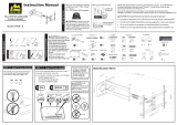
TV Brackets
Parts and Hardware
WARNING: This product contains small items that could be a choking hazard if swallowed. Before starting assembly, verify all parts
are included and undamaged. If any parts are missing or damaged, do not return the damaged item to your dealer; contact Customer Service.
Never use damaged parts!
Parts and Hardware for STEP 1
NOTE: Not all hardware included will be used.
TV Screws
Washers
Spacers
01
x1
15 16 17 18 19 20
21
x4 x4 x4 x4 x4 x4
x4 x4
02
x1

5
10-32 x 3/8 in.
10-32
5/16 in.
5/16 x 2 1/2 in.
Parts and Hardware for STEP 2
Parts and Hardware for Optional Accessory Bracket Mounting
Hardware for Adjustments
Wall Plate
Hex Key
Hex KeyScrew
3/16 in.
Lag Bolts
Bracket WashersCage Nut
1/8 in.
Washers
24
x6
23
x1
28
x2
Anchors (Concrete)
26
x6
25
x6
27
x1
29
x4
30
x4
31
x4
32
x1

6
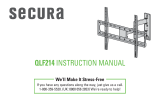
1-1 Select TV Screws
Hand thread screws into the threaded inserts on the back of your TV
to determine which screw diameter (M4, M5, M6, or M8) to use.
1-2 Select TV Spacers
CAUTION: Verify adequate thread engagment of the screw
and spacer combination on your TV.
Too short will not hold the TV and too long will damage the TV.
M4 M6 M8M5
Too Short Correct Too Long
Use spacers
15
or
16
if your TV has a flat back
AND you want your TV
closer to the wall.
Use spacers
17
,
18
or
19
to accommodate:
● Round/irregular back TVs
● TVs with inset mounting holes
● Extra space needed for cables
Spacers and screws are supplied to install your TV bracket.
Determine your preference for spacer configuration when
attaching your TV bracket.
Round Back CablesInset HolesFlat Back
a
b
STEP 1 Attach Brackets to TV
17 18 19
15 16

7
1-3 Attach Spacers to TV Brackets
1
1. Press the shoulder washers
20
through the openings of TV brackets
01
and
02
that line up with your TV hole pattern.
2. Snap shoulder washers
20
into the spacers
15
,
16
,
17
,
18
or
19
you selected in STEP 1-2.
20
15
16
17
18
19
2
20
19
18
17
16
15
0201
02
01

8
1 2 3
1 2 3
1-4 Prepare TV Brackets (ONLY For TV Hole Patterns Wider than 600mm)
NOTE: For TV's with hole patterns wider than 600 mm (≈23 5/8 in.), the placement of TV brackets
01
and
02
must be reversed on your TV
to fit your pattern and still allow hanging onto wall plate
23
. The knobs
K
need to be repositioned to the outside for accessability and tilt
tension adjustments after installation.
1. Unscrew tilt tension knob
K
from the screw on both TV brackets
01
and
02
using hex key
27
.
2. Flip tilt tension knob
K
to the opposite side of TV bracket
01
and
02
.
3. Reattach tilt tension knob
K
onto the screw.
> 600mm
(
≈
23 5/8 in.)
K K
010101
K
02 02 02
KKK
02 01
27
2727
27

9
Center the TV brackets
01
and
02
over your TV hole pattern as shown, making sure the brackets are level with each other.
IMPORTANT: Install with tilt tension knobs
K
toward the outside.
Install using the screw and washer combination [a] or [b] you selected for your TV.
NOTE: Use washer
21
for screws
03
,
04
,
07
,
08
,
11
and
12
.
Use washer
22
for screws
05
,
06
,
09
,
10
,
13
and
14
.
a
Flat Back
b
Round Back / Extra Space
15
17
16
18 19
07
03 04 05
06
08 09 10 11
12 13
14
21
21
22
22
1-5 Attach TV Brackets
01 02
K
K

10
STEP 2A Attach Wall Plate to Wall
Wood Stud Option
CAUTION: Avoid potential personal injuries and property damage!
● Drywall covering the wall must not exceed 5/8 in. (16 mm)
● Minimum wood stud size: common 2 x 4 in. (51 x 102 mm) nominal 1½ x 3½ in. (38 x 89 mm)
● Minimum horizontal space between fasteners: 16 in. (406 mm)
1. Stud centers must be verified – not all walls have conventional 16 in. (406 mm) stud spacing. Verify the center of the stud(s) using an awl, a
thin nail, or an edge to edge stud finder.
2. Level the wall plate
23
and mark the hole locations.
NOTE: For assistance in determining wall plate location, see HeightFinder at sanus.com.
1
2
23
Max.
5/8 in.
(16 mm)
Min.
16 in.
(406 mm)

11
3
4
3. Drill the four pilot holes using a 3/16 in. (5 mm) diameter drill bit.
IMPORTANT: Pilot holes must be drilled to a depth of 2 ½ in. (63 mm).
4. Install the four washers
25
and lag bolts
26
. Tighten all four lag bolts
26
only until the washers
25
are pulled firmly against the wall plate
23
.
CAUTION: Avoid potential personal injury or property damage! All four lag bolts
26
MUST BE firmly tightened to prevent unwanted
movement of the wall plate
23
.
Ensure the wall plate is securely fastened to the wall before continuing on to the next step.
Go to PAGE 14.
25
26
23
3/16 in.
(5 mm)
2½ in.
(63 mm)

12
1
2
STEP 2B Attach Wall Plate to Wall Solid Concrete or Concrete Block Option
CAUTION: Avoid potential personal injuries and property damage!
● Mount the wall plate
23
directly onto the concrete surface
● Minimum solid concrete thickness: 8 in. (203 mm)
● Minimum concrete block size: 8 x 8 x 16 in. (203 x 203 x 406 mm)
● Minimum horizontal space between fasteners: 8 in. (203 mm)
1. Position the wall plate
23
on the wall at your desired height. Level the wall plate and mark the six hole locations.
NOTE: For assistance in determining wall plate location, see Height Finder at sanus.com.
2. Drill six pilot holes using a 1/2 in. (13 mm) diameter drill bit.
IMPORTANT: Pilot holes must be drilled to a depth of 3 in. (75 mm). Never drill into the mortar between blocks.
Min.
8 in.
(203 mm)
23
1/2 in.
(13 mm)
3 in. (75 mm)

13
3
4
3. Insert six anchors
24
.
CAUTION: Be sure the anchors
24
are seated flush with the concrete surface.
4. Install the six washers
25
and lag bolts
26
. Tighten all six lag bolts
26
only until the washers
25
are pulled firmly against the wall plate
23
.
CAUTION: Avoid potential personal injury or property damage! All four lag bolts
26
MUST BE firmly tightened to prevent unwanted
movement of the wall plate
23
.
Ensure the wall plate is securely fastened to the wall before continuing on to the next step.
24
25
26
23

14
Cage Nut Assembly Option
OPTIONAL ClickFit
™
Accessory Bracket Mounting
1
2
NOTE: If not installing this option, Skip to STEP 3 on PAGE 16.
CAUTION: The ClickFit™ Surge Protector Mounting Accessory supports a maximum weight of 3 lb (1.3 kg).
1. Pinch the ends of cage nuts
29
and insert into brackets
28
, then press brackets
28
into the channels on wall plate
23
.
2. Secure your accessory onto brackets
28
with with washers
30
and screws
31
using hex key
32
.
23
28
29
23
31 3032
28

15
Screw Assembly Option
1
2
1. Secure brackets
28
onto your accessory with washers
30
and screws
31
using hex key
32
.
2. Press brackets
28
into the channels on wall plate
23
.
31
30
28
23 28
32

16
STEP 3 Attach TV to Wall Plate
HEAVY! You may need assistance with this step.
1. Hang the TV onto wall plate
23
by hooking the tops of TV brackets
01
and
02
.
2. Gently rest the TV onto wall plate
23
. An audible click ensures the TV is in the locked position.
CAUTION:
Avoid potential injuries or property damage! The ClickStand™
C
on both TV brackets
01
and
02
,
must be locked onto
wall plate
23
to ensure the TV is securely fastened in place.
23
01 02
01
01
02
02
23
23
C
23
1 2

17
27
K
C
23
02 02
Manage Cables
1 2
23 23
01 01
1. Tighten the tilt adjustment knobs
K
with hex key
27
.
CAUTION:
Avoid potential injuries or property damage! Tilt adjustment knobs
K
must be tight when the TV is in the wiring position.
2. Release the ClickStand™
C
on both TV brackets
01
and
02
.

18
43
C
C
23
02
02
23
23
01
01
3. Pull the TV away from the wall enough to extend each ClickStand™
C
.
4. Rest the TV onto wall plate
23
and connect all cables to your TV.

19
65
01 02
23
C
C
23
23
01
02
23
5. Lift the TV enough to lower the ClickStand™
C
on both TV brackets
01
and
02
.
6. Gently rest the TV onto wall plate
23
. An audible click ensures the TV is in the locked position.
CAUTION:
Avoid potential injuries or property damage! The ClickStand™
C
on both TV brackets
01
and
02
,
must be locked onto
wall plate
23
to ensure the TV is securely fastened in place.

20
Adjustments
TILTLEVEL
Your TV should adjust easily when moved, then stay in place.
Adjust the tilt tension knobs
K
if your TV naturally tilts up or down.
NOTE: If you do not intend to adjust the tilt for different viewing locations,
you can tighten the tilt tension knobs
K
to prevent unwanted movement.
K
27
To level your TV, use hex key
27
to turn the level screw
L
on the top of either TV bracket
01
or
02
to raise or lower
that respective side of the TV.
27
L
01 02
01 02
/