DIMENSIONES Y ESPACIOS
Deje el espacio adecuado entre la cocina y las
superficies combustibles adyacentes. Estas
dimensiones se deberán cumplir para un uso seguro
de su cocina.
Deje un espacio mínimo de 30” (76.2 cm) entre
los quemadores y la parte inferior del gabinete de
madera o metal sin protección, o deje un espacio
mínimo de 24” (61 cm) cuando la parte inferior del
gabinete de madera o metal esté protegido por no
menos de 1/4” (6.4 mm) de cartón de retardo de
incendios cubierta por no menos que una lámina
metálica de 28 MSG (.015” (.38 mm) de grosor),
.015” (.38 mm) de grosor de acero inoxidable, .025”
(0.64 mm) de aluminio o .020” (0.5 mm) de cobre.
La instalación de un horno microondas o de un
electrodoméstico de cocción que figuren en la lista
sobre la parte superior de la cocina deberá cumplir
con las instrucciones de instalación provistas con el
electrodoméstico.
Para la instalación de la isla, deje un espacio mínimo
de 2-½” desde la abertura hasta el extremo trasero
de la mesada y un mínimo de 3” desde la abertura
hasta los extremos laterales de la mesada.
CONEXIÓN DEL CONECTOR
HERRAMIENTAS NECESARIAS MATERIALES NECESARIOS
Ŷ9iOYXODGHFLHUUHSDUDWXEHUtDGHJDV
Ŷ6HOODGRUSDUDMXQWDGHWXEHUtDR8/±FLQWDSDUD
tubería aprobada con Teflón*, resistente a la acción
de gases naturales o propano
Ŷ&RQHFWRUSDUDDUWHIDFWRPHWiOLFRIOH[LEOH´,'
Se recomienda una longitud de 5 pies para una
fácil instalación, pero otras longitudes son
aceptables. Nunca use un conector viejo al instalar
una cocina nueva.
Ŷ$GDSWDGRUSDUDXQLyQFyQLFDSDUDODFRQH[LyQDO
VXPLQLVWURGHJDV´Rò´137[ò´,'
Ŷ$GDSWDGRUSDUDXQLyQFyQLFDSDUDODFRQH[LyQDO
regulador de presión en la cocina
´Rò´137[ò´,'
Ŷ'HWHFWRUGHSpUGLGDGHOtTXLGRRDJXDFRQMDEyQ
*Teflón: Marca registrada por DuPont
Regulador
de presión
)OXMRGHO*DVHQOD&RFLQD )OXMRGHO*DVHQOD&RFLQD
&RQHFWRU
flexible
(6 pies máx.)
$GDSWDGRU
Instalador: Informe al consumidor sobre la ubicación de la válvula de cierre de gas.
Tubería de gas
de ½” o ¾”
$GDSWDGRU
9iOYXODGH
cierre de
gas
Regulador
de presión
&RGR
&RGR
Boquilla
roscada
8QLyQ
Boquilla
roscada
9iOYXOD
de cierre
de gas
Tubería de gas
de ½” o ¾”
Opción
Flexible
Opción de
Tubería Rígida
EN EL COMMONWEALTH DE
MASSACHUSETTS
Ŷ(VWHSURGXFWRGHEHVHULQVWDODGRSRUXQSORPHUR
licenciado o un mecánico gasista.
Ŷ$OXVDUYiOYXODVGHFLHUUHGHJDVWLSREDOyQ
deberán ser del tipo de manija T.
Ŷ$OXVDUXQFRQHFWRUGHJDVIOH[LEOHQRGHEHUi
exceder los 5 pies.
ANTES DE COMENZAR
IMPORTANTE — &RQVHUYHHVWDVLQVWUXFFLRQHV
para uso del inspector de electricidad local.
IMPORTANTE — &XPSODFRQWRGRVORV
códigos y ordenanzas gubernamentales.
IMPORTANTE — Retire todo el material
de embalaje y material escrito del horno antes de
conectar el gas y el suministro de corriente a la cocina.
IMPORTANTE — $ILQGHHYLWDUGDxRV
en los gabinetes, controle con su constructor o
proveedor de gabinetes que los materiales usados
no descolorarán, deslaminarán ni sostendrán otro
GDxR(VWHKRUQRIXHGLVHxDGRGHDFXHUGRFRQORV
UHTXLVLWRVGH8/\&6$,QWHUQDWLRQDO\FXPSOHFRQ
las temperaturas máximas permitidas para gabinetes
GHPDGHUDGH)&
Nota para el Instalador±$VHJ~UHVHGHTXHHVWDV
instrucciones queden en manos del comprador.
Nota para el Consumidor±Guarde estas
instrucciones para referencia futura.
Servicio Técnico±(OGLDJUDPDHOpFWULFRVH
encuentra en un sobre adjunto al reverso de la cocina.
La correcta instalación del producto es
responsabilidad del instalador.
Si se producen fallas en el producto debido a
una instalación inadecuada, la Garantía no cubrirá
las mismas.
$QWHVGHLQVWDODUVXFRFLQDVREUHOLQyOHR\FXDOTXLHU
RWURUHYHVWLPLHQWRGHSLVRVLQWpWLFRDVHJ~UHVHGH
que el revestimiento del piso resista los 180º F sin
contraerse, combarse o descolorarse. No instale la
cocina sobre alfombras, a menos que haya una hoja
de contrachapado de un grosor de ¼” o un aislante
similar entre la cocina y la alfombra.
Casa Rodante – Requisitos de Información
Adicional
Esta cocina se deberá instalar conforme con el
(VWiQGDUGH&RQVWUXFFLyQ\6HJXULGDGSDUD+RJDU
7tWXOR&)53LH]D(anteriormente el
(VWiQGDU)HGHUDOSDUDOD&RQVWUXFFLyQ\6HJXULGDG
GH&DVDV5RGDQWHV)HGHUDO6WDQGDUGIRU0RELOH
+RPH&RQVWUXFWLRQDQG6DIHW\7tWXOR+8'3DUWH
&XDQGRGLFKRHVWiQGDUQRVHDDSOLFDEOH use el
HVWiQGDUSDUDODV,QVWDODFLRQHVGH&DVDV)DEULFDGDV
$16,$1)3$$RFRQFyGLJRVORFDOHV
(Q&DQDGiODLQVWDODFLyQGHHVWDFRFLQDGHEHUi
ser realizada de acuerdo con los estándares
DFWXDOHV&$1&6$$±~OWLPDHGLFLyQRFRQORV
códigos locales.
&XDQGRODFRFLQDHVLQVWDODGDHQXQDFDVDPyYLOVH
GHEHUiDVHJXUDUDOSLVRGXUDQWHHOWUiQVLWR&XDOTXLHU
método para asegurar la cocina es adecuado,
siempre y cuando se realice conforme con los
estándares que figuran a continuación.
ADVERTENCIA
RIESGO DE INCENDIO O
EXPLOSIÓN
Si la información de este manual no se sigue
exactamente, se podrá producir un incendio o
H[SORVLyQRFDVLRQDQGRGDxRVVREUHODSURSLHGDG
lesiones o la muerte.
La instalación deberán ser realizadas por un
instalador calificado.
Lea estas instrucciones en su totalidad y atentamente.
Esta cocina se deberá instalar de acuerdo con
los códigos locales, o en la ausencia de códigos
ORFDOHVFRQHO&yGLJRGH*DV&RPEXVWLEOH1DFLRQDO
$16,=1)3$~OWLPDHGLFLyQ(Q&DQDGi
ODLQVWDODFLyQGHEHUiVHUFRQIRUPHFRQHO&yGLJRGH
,QVWDODFLyQGH*DV1DWXUDODFWXDO&$1&*$%
RHO&yGLJRGH,QVWDODFLyQGH3URSDQRDFWXDO&$1
&*$%\FRQORVFyGLJRVORFDOHVFXDQGR
FRUUHVSRQGD(VWDFRFLQDIXHGLVHxDGD\FHUWLILFDGDSRU
&6$,QWHUQDWLRQDOGHDFXHUGRFRQ$16,=~OWLPD
HGLFLyQ\FRQOD&DQDGLDQ*DV$VVRFLDWLRQ$VRFLDFLyQ
GH*DVGH&DQDGi&$1&*$~OWLPDHGLFLyQ
$OLQVWDODUXQHOHFWURGRPpVWLFRDJDVHOXVRGH
conectores flexibles viejos puede ocasionar pérdidas
y lesiones personales. Siempre use un conector
IOH[LEOH18(92
La prueba de goteras del electrodoméstico se
deberá realizar de acuerdo con las instrucciones del
fabricante.
La cocina deberá estar correctamente conectada
a tierra de acuerdo con los códigos y ordenanzas
locales o, en ausencia de códigos locales, de acuerdo
FRQHO&yGLJR1DFLRQDOGH(OHFWULFLGDG1DWLRQDO
(OHFWULF&RGH$16,1)3$12~OWLPDHGLFLyQ
(Q&DQDGiODFRQH[LyQDWLHUUDVHGHEHUiUHDOL]DUGH
DFXHUGRFRQOD3DUWHGHO&yGLJRGH(OHFWULFLGDGGH
&DQDGi&6$&\RORVFyGLJRVORFDOHV(QHVWD
VHFFLyQFRQVXOWHODV&RQH[LRQHV(OpFWULFDV
No instale este producto con una campana con cortina
de aire u otra campana de cocina que funcione llevando
aire a la placa de cocción. El flujo de aire podrá
interferir en el funcionamiento de los quemadores de
gas, produciendo riesgos de incendio o explosión.
1
SUMINISTRO DE GAS
ADVERTENCIA
Riesgo de incendio:
No use una llama para controlar las pérdidas de gas.
ADVERTENCIA
Riesgo de
Explosión: No supere una torsión máxima de 25
pies-libras al realizar conexiones de tuberías de
gas. Cualquier ajuste en exceso podrá romper
el regulador de presión, resultando en riesgo de
incendio o explosión.
Regulador de Presión de Gas
Se deberá usar el regulador de presión de gas
suministrado con esta cocina. Para un funcionamiento
adecuado, la presión de entrada al regulador deberá
ser la siguiente:
Gas Natural:
3UHVLyQPtQLPD&ROXPQDGH$JXDGH´
3UHVLyQPi[LPD&ROXPQDGH$JXDGH´
Gas Propano:
3UHVLyQPtQLPD&ROXPQDGH$JXDGH´
3UHVLyQPi[LPD&ROXPQDGH$JXDGH´
Si no está seguro sobre cuál es la presión de entrada,
comuníquese con el proveedor de gas local.
Cierre la válvula principal de suministro de gas
antes de desconectar su vieja cocina y deje la
misma apagada hasta que la nueva conexión se
haya completado. No olvide volver a encender el
piloto en otros electrodomésticos a gas cuando
vuelva a encender el gas.
Debido a que las tuberías duras restringen el
movimiento de la cocina, se recomienda el uso del
conector para electrodomésticos de metal flexible con
FHUWLILFDFLyQLQWHUQDFLRQDOGH&6$DPHQRVTXHORV
códigos locales requieran una conexión de tubería dura.
Si se usa el método de tubería dura, deberá alinear la
misma con cuidado; la cocina no se podrá mover una
vez realizada la conexión.
Para evitar pérdidas de gas, coloque el compuesto
de la junta de gas, o envuelva la cinta para roscas de
tuberías con Teflón* alrededor de todas las roscas de
tubería macho (externas).
$,QVWDOHXQDYiOYXODGHFLHUUHPDQXDOGHODOtQHDGH
gas en la línea de gas, en una ubicación de fácil
DFFHVRIXHUDGHODFRFLQD$VHJ~UHVHGHTXHWRGDV
las personas que usen la cocina sepan dónde y
cómo cerrar el suministro de gas de la cocina.
%,QVWDOHHODGDSWDGRUGHODXQLyQFyQLFDPDFKRGH
½” a la rosca interna de 1/2” de NPT en la entrada
GHOUHJXODGRU8VHODOODYHGHUHSXHVWRHQHO
DFFHVRULRUHJXODGRUSDUDHYLWDUGDxRV
$OLQVWDODUODFRFLQDGHVGHHOIUHQWHUHWLUHHOFRGR
de 90º para una instalación más fácil.
&,QVWDOHXQDGDSWDGRUSDUDXQLyQFyQLFDGHò´Rô´
a la rosca interna de NPT de la válvula de cierre
manual, procurando evitar que la válvula de cierre
no gire.
'&RQHFWHHOFRQHFWRUGHPHWDOIOH[LEOHGHO
electrodoméstico al adaptador de la cocina.
Posicione la cocina para permitir la conexión en la
válvula de cierre.
(&XDQGRWRGDVODVFRQH[LRQHVVHKD\DQUHDOL]DGR
DVHJ~UHVHGHTXHWRGRVORVFRQWUROHVGHODFRFLQD
estén en la posición de apagado y encienda
ODYiOYXODGHVXPLQLVWURSULQFLSDOGHJDV8VH
un detector de pérdida de líquido en todas las
uniones y conexiones, para controlar pérdidas en
el sistema.
$OXVDUSUHVLyQVXSHULRUDòSVLJSDUDFRQWURODU
la presión del sistema de suministro de gas de la
residencia, desconecte la cocina y la válvula de
cierre individual de la tubería de suministro de gas.
$OXVDUODVSUHVLRQHVGHSUXHEDGHòSVLJRPHQRV
para controlar el sistema de suministro de gas,
simplemente aísle la cocina del sistema de suministro
de gas, cerrando la válvula de cierre individual.
$OFRQWURODUHOIXQFLRQDPLHQWRDGHFXDGRGHOUHJXODGRU
la presión de entrada deberá ser por lo menos 1”
mayor que la presión de funcionamiento (tubo) como
en la etiqueta de calificación del producto.
*Teflón: Marca registrada por DuPont
2
CONEXIONES ELÉCTRICAS
ADVERTENCIA
Riesgo de
Descarga: Este electrodoméstico deberá estar
conectado a tierra de forma adecuada. Si no cumple
con esto se podrán producir descargas eléctricas.
Requisitos Eléctricos - &LUFXLWRHVSHFtILFRGH
YROWLRV+HUW]FRUUHFWDPHQWHFRQHFWDGRDWLHUUDSRU
un disyuntor de 15 o 20 amperes o fusible de retraso.
NOTA: No se recomienda para este producto el
uso de interruptores automáticos, inalámbricos o
con cableado externo que apagan la corriente del
electrodoméstico.
Conexión a Tierra
El cable de corriente de este electrodoméstico cuenta
con un enchufe de 3 patas (conexión a tierra) que
se conecta a un tomacorriente de pared estándar de
3 cables para minimizar la posibilidad de riesgos de
descargas eléctricas por parte del mismo.
El cliente deberá contratar a un electricista calificado
para que controle el circuito, a fin de asegurar que el
tomacorriente esté correctamente conectado a tierra.
En caso de contar con un tomacorriente de pared de
2 cables, es la responsabilidad y obligación del cliente
reemplazarlo por un tomacorriente de pared de 3
cables correctamente conectado a tierra.
NUNCA, BAJO NINGUNA CIRCUNSTANCIA,
CORTE NI ELIMINE EL TERCER CABLE (TIERRA)
DEL CABLE DE CORRIENTE. NO USE UN
ADAPTADOR. NO USE UN PROLONGADOR.
1RVHUHTXLHUHQQLVHUHFRPLHQGDQ,QWHUUXSWRUHVFRQ
'HWHFFLyQGH)DOODD7LHUUD*)&,HQUHFHSWiFXORVGH
cocinas a gas. El funcionamiento de la cocina no se
YHUiDIHFWDGRVLVHXWLOL]DHQXQFLUFXLWR*)&,SURWHJLGR
pero es posible que se produzcan detenciones
RFDVLRQDOHVQRGHVHDGDVGHOLQWHUUXSWRU*)&,
PARA SU SEGURIDAD
$VHJ~UHVHGH
contar con una
conexión a tierra
adecuada antes
de usar.
CUANDO TODAS LAS
CONEXIONES SE HAYAN
COMPLETADO
$VHJ~UHVHGHTXHWRGRVORVFRQWUROHVTXHGHQHQOD
SRVLFLyQGHDSDJDGR$VHJ~UHVHGHTXHHOIOXMRGHOD
combustión y el aire de ventilación a la cocina estén
desobstruidos.
$VHJ~UHVHTXHWRGRVORVPDWHULDOHVGHHPSDTXH\
cintas se hayan retirado. Esto incluye cintas sobre
el panel metálico debajo de las perillas de control (si
corresponde), cinta adhesiva, cintas de ajuste, cartón
y plástico protector. Si estos materiales no se retiran,
VHSRGUiSURGXFLUFRPRUHVXOWDGRXQGDxRVREUHHO
electrodoméstico, una vez que el mismo haya sido
encendido y las superficies estén calientes.
ADVERTENCIA
$QWHVGH
comenzar la instalación, apague el encendido
en el panel de servicio y bloquee el medio de
desconexión del servicio a fin de evitar que
el encendido se active de forma accidental.
&XDQGRHOPHGLRGHGHVFRQH[LyQGHOVHUYLFLR
no se pueda bloquear, ajuste de manera segura
un ítem de advertencia que esté bien visible, tal
como una etiqueta, sobre el panel de servicio.
Kit de soporte
anti-volcaduras incluido
Si no recibió un soporte anti volcaduras con su compra,
llame al 1.800.626.8774 para recibir uno sin costo.
(Q&DQDGiOODPHDO3DUDUHFLELU
instrucciones de instalación del soporte, visite:
*($SSOLDQFHVFRP(Q&DQDGi*($SSOLDQFHVFD
Destornillador con
cabeza plana
Llave para tubería (2)
(una de repuesto)
Destornillador Philips
Llave con extremo
abierto o ajustable
Lápiz y regla
Nivel
Taladro, punzón
o clavo
7
NIVELACIÓN DE LA COCINA
ADVERTENCIA
Nunca retire
completamente las patas niveladoras, ya que la
cocina no estará asegurada de forma adecuada al
dispositivo anti-volcaduras.
A. Enchufe la unidad.
B. Mida la altura de su mostrador de encimera en la
parte trasera de la abertura (X).
C. $MXVWHODVGRVSDWDVGHQLYHODFLyQWUDVHUDVSDUD
que la parte trasera de la estufa se encuentre a la
misma altura o más arriba que la mesada (Y).
D. Deslice la unidad en su lugar.
E. ,QVWDOHORVHVWDQWHVGHOKRUQRHQODXQLGDG\
coloque la cocina donde se instalará.
F. &RQWUROHODQLYHODFLyQFRORFDQGRXQQLYHOGH
burbuja de aire sobre uno de los estantes
GHOKRUQR+DJDGRVOHFWXUDV±FRQHOQLYHOXELFDGR
en diagonal primero en una dirección
y luego en la otra.
G. $MXVWHODVSDWDVGHQLYHODFLyQIURQWDOHVKDVWDTXH
la cocina quede nivelada.
H.
2EVHUYHGHEDMRGHODXQLGDG\YHULILTXHTXHOD
pata trasera esté completamente adherida al
dispositivo antivolcaduras. De no ser así, retire la
unidad y ajuste la altura de la pata trasera de modo
que quede correctamente adherida.
Instrucciones de instalación
Cocina
¿Preguntas? Llame a GE Appliances al 800.GE.CARES (800.432.2737) o visita
www.GEAppliances.com. En Canadá, llame 1.800.561.3344 o visita www.GEAppliances.ca.
• Un niño o adulto pueden volcar la cocina y morir.
• Instale el soporte anti-volcaduras sobre la pared o el piso.
•
Asegúrese la estufa al soporte anti-volcaduras deslizando
la unidad hacia atras de tal manera que la pata niveladora
sea enganchada.
• Vuelva a adherir el soporte anti-volcaduras si la estufa
se mueve de lugar.
• Si esto no se hace, se podrá producir la muerte o
quemaduras graves en niños o adultos.
Riesgo de Caída
ADVERTENCIA
CONVERTIR A GAS PROPANO
(O VOLVER A CONVERTIR DE
PROPANO A GAS NATURAL)
Esta cocina deja la configuración de fábrica para uso
con gas natural. Si desea convertir a gas propano, la
conversión deberá ser realizada por un instalador de
gas propano calificado.
Los orificios de conversión y las instrucciones se
podrán encontrar en la parte trasera de la cocina.
Guarde estas instrucciones y todo orificios en caso
de que lo desee convertir nuevamente a gas natural.
INSTALACIÓN EN ALTITUDES ELEVADAS
$PiVGHSLHVHOSURGXFWRFRQILJXUDGRSDUDJDVQDWXUDORSURSDQRUHTXLHUHODLQVWDODFLyQGHONLW
:%;6LJDODVLQVWUXFFLRQHVLQFOXLGDVFRQHONLW
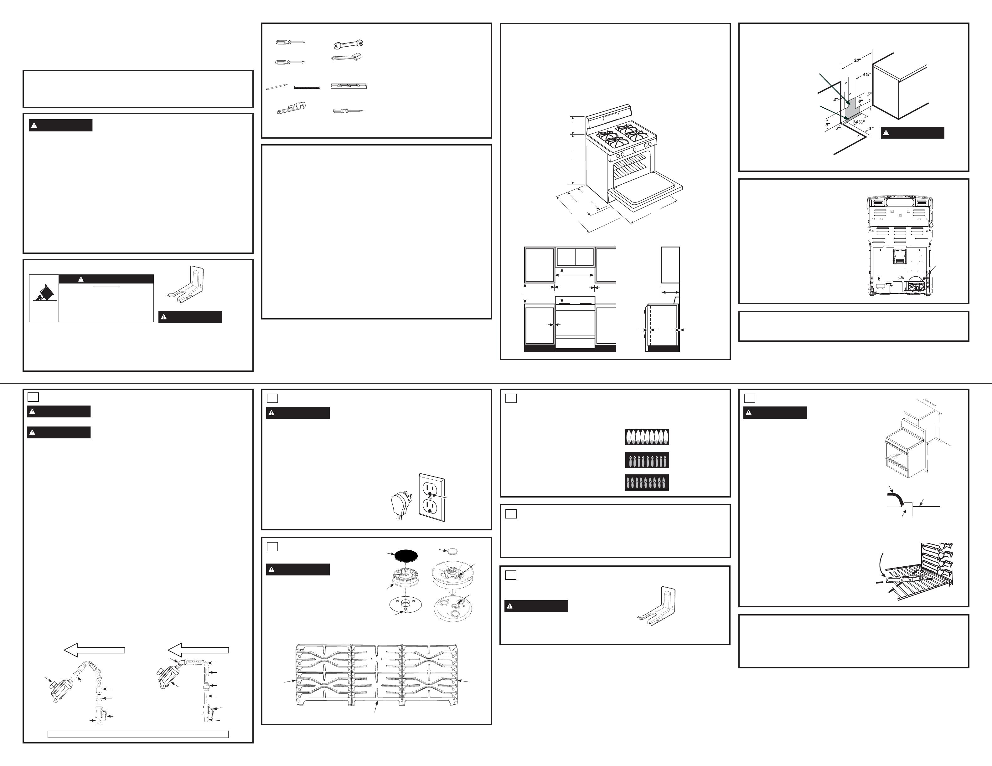
DIMENSIONES Y ESPACIOS
(CONT.)
UBICACIONES DE LA TUBERÍA DE GAS Y DEL TOMACORRIENTE ELÉCTRICO
6
INSTALE Y CONTROLE EL
DISPOSITIVO
ANTIVOLCADURAS
ADVERTENCIA
Nunca retire
completamente las patas niveladoras, ya que la
cocina no estará asegurada de forma adecuada al
dispositivo antivolcaduras.
Siga las instrucciones suministradas con el soporte
$17,92/&$'85$6
Kit de soporte
anti-volcaduras
incluido
Espacio mínimo
con relación a la
pared izquierda
Mínimo para
gabinetes en
cada lado de
la parrilla
30”
30”
Mínimo
15”
3”
Espacio mínimo
con relación a la
pared derecha
Profundidad
mínima para
gabinetes sobre
mostradores
Extremo
frontal del
panel lateral
de la cocina
adelante del
gabinete
0”
Para gabinetes
debajo de la parte
superior de la
cocina y la parte
trasera de la cocina
1/4”
6”
0”
18”
Para
gabinetes
debajo de
la parte
superior de
la cocina y la
parte trasera
de la cocina
Área recomendada para tomacorriente de
9HQODSDUHGWUDVHUD\iUHDSDUDOD
conexión del tubo de escape y la válvula de
seguridad a través de la pared.
Área recomendada para conexión
a través del piso del tubo de
escape y la válvula de seguridad.
PRECAUCIÓN
Para
evitar que una corriente de aire afecte
el funcionamiento del quemador, selle
todas las aberturas sobre el piso
debajo del electrodoméstico y detrás
de la pared del mismo.
Parte Trasera de la Estufa
&DMDGHO
2ULILFLR
(la ubicación
puede variar)
4
CONTROLE LAS CABEZAS
DE LOS QUEMADORES
3UHVLRQH\JLUHODSHULOODDODSRVLFLyQ/,7(
(Luz). Escuchará un sonido de clic, que indica el
funcionamiento adecuado del módulo de chispeo.
8QDYH]TXHHODLUHVHKD\DSXUJDGRGHODV
líneas de suministro, los quemadores se deberán
encender dentro de los 4 segundos. Luego de que
los quemadores se iluminen, gire la perilla fuera de
ODSRVLFLyQ/,7(3UXHEHFDGDTXHPDGRUGHIRUPD
sucesiva hasta que todos los quemadores hayan sido
controlados.
Calidad de las Llamas
La calidad de las llamas de los quemadores se
deberá determinar visualmente.
Si las llamas del quemador se ven como en (A),
llame al servicio técnico. El aspecto de la llama
normal se ve como en (B) o (C), dependiendo del
tipo de gas que use.
&RQJDVSURSDQRHVQRUPDOTXHKD\DDOJXQDVSXQWDV
amarillas en los conos externos.
INSTRUCCIONES DE INSTALACIÓN
31-10998-3 06-17 GEA
JGBS62, JGB645, JGBS66, JGB660, JGB700
5
CONTROLE LOS
QUEMADORES PARA
HONEAR Y ASAR
ŶConfigure la función Bake (Hornear) en 350º F.
El quemador se deberá iluminar entre 30 y 90
segundos.
ŶControle el quemador para asar usando el
mismo método que con el quemador para
hornear.
(C) Llamas azul suave —
Normal para gas natural
(B) Puntas amarillas en
conos externos —
Normal para el gas propano
(A) Llamas amarillas —
Llame al servicio técnico
1LYHOGH$JXD
X
Y
46 1/4"
28 3/4"
w/ handle
26 1/4"
w/o handle
30"
36 1/4" ± 1/4"
11 1/4"
Sin manija
Con manija
3
SUPERFICIALES
QUEMADORES
ADVERTENCIA
Riesgo de Incendio
o Explosión: No use el quemador sin que todas
las partes de los quemadores estén en sus
respectivos lugares.
$ Quemadores -&RORTXHODVFDEH]DVGHORV
quemadores en las posiciones correspondientes
en la placa de cocción.
B. Tapas - &RORTXHODVWDSDVHQORVTXHPDGRUHVGH
ORVWDPDxRVFRUUHVSRQGLHQWHV
& Rejillas Individuales -&RORTXHHOHQVDPEOHGHOD
cabeza/ tapa ovalada (centro) sobre el electrodo
en la placa de cocción.
Rejilla
,]TXLHUGD
Rejilla
Derecha
5HMLOODR3ODQFKD&HQWUDO
o
Quemador frontal derecho
Electrodo
Electrodo
$JXMHUR
Tapa
Quemador
Tapa
NOTA: La placa de cocción debe estar a la
misma altura o más arriba que la mesada.
Rejilla
3ODFDGH&RFFLyQ
Mesada


