Page is loading ...

Unifarm Machinery Corporation
PO Box 38, Wilson, NC, U.S.A.
page 1
Unifarm Machinery Corporation
PO Box 38, Wilson, NC
Operator’s Manual MOWERS
ATTENTION
Carefully read this manual
before using the machine
M48-S M48-A M60-S M60-A M72-S M72-A M84-S M84-A
903182002
-
00

Unifarm Machinery Corporation
PO Box 38, Wilson, NC, U.S.A.
page 2

Unifarm Machinery Corporation
PO Box 38, Wilson, NC, U.S.A.
page 3
Unifarm Machinery Corporation
PO Box 38, Wilson, NC, U.S.A.
252-291-3997 Fax: 252-291-7354
Dealer’s
Stamp
No part of this manual shall be reproduced, copied or disseminated by any means, without Unifarm
Machinery Corporation’s prior authorization in writing.
Unifarm Machinery Corporation reserves the right to make any necessary changes without giving
prior notice, in order to optimize the quality and safety features and does not commit itself to
updating this manual every time a change is made.
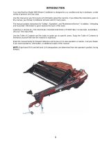
This booklet provides a thorough and accurate description of the instruction and maintenance
activities to be carried out on the tiller you purchased. We congratulate you on your choice and
urge you to thoroughly familiarize yourself with and follow the instructions contained in this manual.
This will assure you a long, safe and trouble free working life for your Phoenix Tiller.
The Manufacturer shall not assume any responsibility should problems arise as a result of
lack of compliance with the instructions and/or operator’s negligence.
The manual is divided in chapters and paragraphs and the pages are numbered, thus offering
accurate and precise information.
The requested information can be easily found by searching the key words or referring to the index.

Unifarm Machinery Corporation
PO Box 38, Wilson, NC, U.S.A.
page 4
INDEX
GENERAL INFORMATION
Symbols Page 5
Safety labels Page 6
Technical data Page 7
Main parts Page 7
Identification plates Page 8
Recommended use Page 8
Inappropriate use Page 8
Torque specification Page 8
SAFETY
Safety in the workplace Page 9
User’s requirements Page 9
Work clothing Page 9
General safety norms Page 9
SET UP
Assembling Page 11
Front roller kit Page 12
Attachment to the tractor Page 13
Connection to PTO shaft Page 14
Cutting height adjustment Page 14
Belts adjustment Page 15
Start up Page 15
Road transport Page 16
Shut down Page 16
MAINTENANCE
Program Page 16
Blade replacement Page 18
Spare parts Page 18

Unifarm Machinery Corporation
PO Box 38, Wilson, NC, U.S.A.
page 5
GENERAL INFORMATION
SYMBOLS
This booklet contains three “safety pictograms” which highlight the relevant danger levels or
important information:
It draws the operator’s attention to special situations which
may jeopardize people’s safety.
It draws the attention to situations which unfavourably affect
the machine efficiency, but not people’s safety.
It is used for general information, when people’s safety or
the efficiency of the parts are not at risk.

Unifarm Machinery Corporation
PO Box 38, Wilson, NC, U.S.A.
page 6
SAFETY LABELS
The safety labels and information on the machine, described in, must be complied with. Failure to
comply with these warnings may result in severe injuries or even death. Make sure that the labels
are always present and legible; should this not be the case, contact your nearest PHOENIX dealer to
request replacements.
1 2 3 4
5 6 7 8

Unifarm Machinery Corporation
PO Box 38, Wilson, NC, U.S.A.
page 7
TECHNICAL DATA
MAIN PARTS TERMINOLOGY
A) Main Frame
B) Lower Hitch Blocks
C) Top Link Coupling
D) PTO Attach
E) Third Point Mast
F) Cover
G) Transmission Case
H) Wheel
Specifications M48-S M48-A M60-S M60-A M72-S M72-A M84-S M84-A
Tires Solid Air Solid Air Solid Air Solid Air
Cutting width 48’’ 60’’ 72’’ 84’’
Cutting height range ¾’’ - 4 ¼’’ 1 ½’’ - 4 ½’’
Blade Speed (rpm) 3130 2650 2240 2030
Blades number 3 3 3 3
HP max requirement 30 40 50 60
PTO Input (rpm) 540 540 540 540
Weight (lbs) 392 432 472 816
Gearbox Oil Type EP SAE 80W/90
Oil quantity (gal) 0,20

Unifarm Machinery Corporation
PO Box 38, Wilson, NC, U.S.A.
page 8
IDENTIFICATION PLATES
The identification plates are placed on all the mowers and are structured as follows:
Model of mower (example): Serial number (example):
When asking for information or service, always specify the
machine type and the width.
RECOMMENDED USE
The mowers of Unifarm Machinery Corporation, described in this instruction and maintenance
manual, have been designed explicitly to till the land. Any other use jeopardizes the operator’s
safety and the machine integrity.
INAPPROPRIATE USE
Phoenix mowers shall not be used as follows:
- Connected to vehicles which do not have a suitable power or weight.
- Without being properly installed by securing the hitch blocks to all three points of the tractor lift
unit.
- Mowing of extremely stony or unsuitable ground.
- Raising or lifting of the equipment when the power take off is engaged.
- In close proximity to person/s when power is engaged.
- Do not stand or step on the equipment when it is being operated or transported.
- Do not operate the machinery while wearing unsuitable (loose fitting) clothing.
TORQUE SPECIFICATION
For correct hardware tightening on the tiller, we suggest the use of suitable torque wrench and the
applicable torque as listed in the table below:
M-THREADED SCREW/BOLTS
Bolt grade
8.8 10.9
Thread
Nm Lb-ft Nm Lb-ft
M6 11 8.5 17 12
M8 28 20 40 30
M10 55 40 80 60
M12 95 70 140 105
M14 150 110 225 165
M16 240 175 305 225
M18 330 250 475 350

Unifarm Machinery Corporation
PO Box 38, Wilson, NC, U.S.A.
page 9
SAFETY
SAFETY IN THE WORKPLACE
Most of the accidents, which occur while the operator is using the machine or the equipment or
carrying out maintenance and repair activities, are caused by the non-compliance with the main
safety requirements.
Therefore the potential risks must be fully understood and special attention must be paid to the
activity which is being executed.
If potentially dangerous situations are known,
accidents can be prevented!
USER’S REQUIREMENTS
The equipment user must have the following:
Physical: good sight, co-ordination and capability to execute all instructions in a safe manner.
Mental: the users must understand and follow the prescribed norms, rules and safety measures.
They must be careful, pay attention to their own safety and the safety of other people and act
properly and in a responsible way.
Training: the users must read and understand this manual, its pictures and charts, and the
identification and hazard plates. They must be trained and qualified to perform any use and
maintenance activities.
WORK CLOTHING
The following clothing and personal protective equipment must be used when working and executing
maintenance and repair activities:
- Overalls or any other comfortable outfit; make sure that they are not too loose since they
might be caught by moving parts.
- Protective gloves.
- Goggles or mask to protect the eyes and face.
- Safety helmet.
- Safety shoes.
Make sure that the personal protective equipment is properly
stored and complies with the laws in force.
GENERAL SAFETY NORMS
The features of the area where work is taking place must always be taken into consideration:
- Do not stand in the working radius of the operating machinery or any other machine accessories
when the equipment is running.

Unifarm Machinery Corporation
PO Box 38, Wilson, NC, U.S.A.
page 10
Prepare the work:
- Do not drink alcohol, take drugs, or any other substances which may affect the your ability to
use the equipment before or when working.
- Make sure that there is sufficient fuel in the tractor to prevent the machine from stopping during
work.
- Do not use the equipment under unsafe conditions, e.g. do not make temporary repairs just to
start or keep working; do not work at night if the area is not well illuminated.
When working or executing maintenance activities, remember:
- The labels and stickers providing instructions on the use of the equipment or information on
dangers must not be removed or hidden, and must be legible.
- Do not remove the safety devices, covers and safety guards, unless maintenance activities are
being carried out. If the safety devices must be removed, turn the engine off, remove them
correctly and re-install them before turning the tractor on.
- Do not lubricate, clean or adjust moving parts.
- Use the appropriate tools to execute maintenance or adjustment activities on the equipment.
- Do not use damaged or unsuitable tools, e.g. pliers rather than wrenches etc.
- Prior to carrying out activities on hydraulic lines under pressure, or disconnecting their
components, make sure that the line is no longer under pressure and that it does not contain
any hot fluids.
- Check all the fittings and make sure that they are well connected before supplying pressure to
the hydraulic lines.
- Make sure that no tools, clothes or any other materials are left in areas where moving parts are
present when the maintenance and repair activities are completed.
- Do not give directions and make signals at the same time during a manoeuvre. Manoeuvre
directions and signals must be given from one person only.
- Do not unexpectedly call an operator, if not necessary. Do not startle the operator, e.g. by
throwing objects.
- Pay attention to people in the vicinity of the work area, especially children!
- Make sure that nobody is standing in the working range of the equipment.
- Do not use the equipment to lift people.
- When the equipment is not needed, turn the engine off, leave the vehicle on a flat surface, with
the first gear and the parking brake engaged. Disengage the power take off.
- Do not execute any cleaning, lubrication, repair or adjustments when the engine is running and
the equipment is in the raised position.
- Do not work on steep slopes, if the stability of the vehicle can be jeopardized.
UNIFARM MACHINERY CORPORATION shall not assume any responsibilities if these
instructions are not strictly followed.

Unifarm Machinery Corporation
PO Box 38, Wilson, NC, U.S.A.
page 11
SET UP
ASSEMBLING
The mower is delivered in parts to be assembled; for correct assembly, respect the following
instructions:
Stage 1
Place the wheel supports (2) on the
machine frame, and tighten the four
bolts (4) with washers (5) and nuts
(6). Insert the four wheels (1) in the
support bushings, and adjust the cut
height by means of the spacers (3).
Stage 2
Place the belts (7) onto the pulleys.
Place the gearbox support (8) on the
machine, insert both belts in the
gearbox pulley guides (9), and
tighten the four mounting bolts (10).
Loosen the screws (11) and adjust
the belt tensioning by means of the
adjustment screw (12); finally
tighten the four screws (11).

Unifarm Machinery Corporation
PO Box 38, Wilson, NC, U.S.A.
page 12
Stage 3
Place the covers (13) on the belts,
tighten the handles on the frame
(14) and on the gearbox support
(15). Anchor the PTO shield (16) by
means of four screws (17) and the
washers (18).
Stage 4
Install the uprights (19) on the
machine and insert the bolts (21),
and relative nuts (22). Install the tie-
rods (20) on the machine and insert
the bolts (23), with relative nuts
(24). Place the top link (25) on both
tie-rods and uprights, by inserting
the spacer (26) between the top link
and the tie-rods; finally tighten the
screw (27) with the nut (28) and the
washer (29). Make sure that the top
link turns freely on the bolt. Finally
tighten the bolts (21) with the nuts
(22) and the bolts (23) with the nuts
(24). Install the lower hitches (30) on
the supports (31); adjust the length
and install the pins (32) anchoring
them by means of the split pins (33).
FRONT ROLLER KIT
On demand it is possibile to install on the front part of the
machine a levelling roller, which improves
the work of the
machine, smoothing small obstacles and roughnesses of the
land. To install the roller on the mower:
- attach the roller A to the mower inserting the bolts B
into the right holes;
- tighten the screws B with the nuts supplied within the
kit.
These activities must be carried out with the engine off,
the power take off disengaged and the hand brake
applied. If needed, lift the equipment and place it on
supports, thus preventing any injuries that might be
caused by a sudden fall of the equipment.

Unifarm Machinery Corporation
PO Box 38, Wilson, NC, U.S.A.
page 13
ATTACHMENT TO THE TRACTOR
Carefully read this instruction manual and the manuals of
the tractor and PTO shaft manufacturer. All Phoenix
mowers are built to be attached to any tractor equipped
with a three point lift of the correct category and with
suitable ball ends.
Before attaching the equipment to the tractor, make sure
that the ground is smooth and flat and that nobody is
standing between the tractor and the mower; slowly move
the tractor towards the mower by aligning the tractor lifter
arms with the two mower coupling side pins; turn the
engine off and pull the brake.
It is possible to adjust the attachment position by releasing
the pins A (picture 1) and modifying the position of the
plates B.
picture 1
After adjusting the couplers, connect the lower arms by removing the catch pins from the pins
located on the hitch blocks, inserting the lift arm pins through the hitch block and ball ends and
secure them by means of the pins which were previously removed.
Connect the tractor top link to the third
upper point by removing the pin located
between the two plates, inserting the top
link and securing it by means of the pin.
Adjust the top link so that the upper part
of the frame is parallel to the ground.
Block all the linking parts by m
eans of the
sway chains or arms.
Make sure that the central unit axis
(case/bevel gear pair) is parallel to the
ground, thus minimizing the stresses on
the power take off and increasing the
working life of the equipment.
After executing all the above-mentioned activities, make
sure that all the nuts and bolts are tightened.

Unifarm Machinery Corporation
PO Box 38, Wilson, NC, U.S.A.
page 14
CONNECTION TO THE PTO SHAFT
Before installing the PTO shaft make sure that the RPM rating and the direction of rotation match
those of the tractor. Carefully read the PTO shaft and tractor instructions.
Furthermore, accurately read the instructions of the manufacturer of the PTO shaft and of the
tractor.
Before starting any activity, make sure that the guards are installed on the power take off of the
tractor and PTO shaft. Make sure that they cover the PTO shaft throughout its length.
When fully extended, the plastic pipes must overlap by at
least 1/3 of the length of the pipes (LT). When retracted, the
min. acceptable clearance is 1-2 cm (picture 6).
picture 6 Check that th
e PTO shaft min. and max.
length are within the parameters of the
machine-tractor coupling.
Should problems arise, contact your
dealer. After the installation, anchor the
PTO shield to the tractor and machine
using the special chains; make sure that
it turns smoothly. If the PTO shaft is
equipped with safety devices, e.g. torque
limiters or free-wheel devices, install
them on the operative machine side. For
the use and maintenance of the PTO
shaft, please refer to the relevant
manual.
picture 3CUTTING HEIGHT ADJUSTMENT
The cutting height of the equipment depends on the
position of the wheels.
If the wheels are raised, the cutting height increases;
if the wheels are lowered, the cutting height
decreases.
Make sure that the wheels are set at the same height
on both sides.
To adjust the cutting height on the mowers loosen and
remove pin A (picture 3) and adjust the wheels height
according to the bushing B. When the adjustment is
completed, reinsert the pin A.

Unifarm Machinery Corporation
PO Box 38, Wilson, NC, U.S.A.
page 15
BELTS ADJUSTING
In the Phoenix mowers it is possibile to adjust the tension of the belts; the right belts tensioning
insures that the machine works in the right way and decreases the wear of rotating parts. To adjust
the belts tensioning:
picture 4- unscrew the handles A (picture 5) and take off
the shields B and C;
- screw or unscrew the bolt A (picture 6) to adjust
the tension of the belts; if you turn the screw in
clockwise direction the belts are tensioned, while
turning it counterclockwise they are loosened;
when the belt is correctly tensioned it can be
lowered in the middle part not more than 10mm
(picture 4)
- reassemble the carters B and C
picture 5 picture 6
These activities must be carried out with the engine off, the
power take off disengaged and the hand brake applied. If
needed, lift the equipment and place it on supports, thus
preventing any injuries that might be caused by a sudden fall
of the equipment.
START UP
After carrying out these adjustments, the equipment is ready for use. When at the working area, do
not start the power take off with the tiller in working position in the ground. Be sure to lift it by a
few centimetres using the tractor lift. Start the engine, engage the power take off, lower the
equipment to its working position and start.

Unifarm Machinery Corporation
PO Box 38, Wilson, NC, U.S.A.
page 16
ROAD TRANSPORT
With reference to road transport, follow local traffic regulations.
SHUT DOWN
The following activities are recommended if the tiller will not be used for a long period of time:
- Clean and dry the equipment.
- Inspect the equipment and replace the damaged or worn parts if necessary.
- Tighten all the screws and nuts.
Lubricate and cover the machine with a tarpaulin and store it in a dry place.
MAINTENANCE
Maintenance is crucial for the working life and efficiency of any agricultural equipment. If the
equipment is properly maintained and operated, a long working life and operator safety are assured.
The maintenance intervals indicated in this booklet are provided as a mere reference and are related
to normal working conditions; changes may occur depending on the type of activities, environmental
dust, seasonal factors, etc.
- Before injecting lubricating grease into the grease
fittings, clean the fittings to prevent mud, dust, or any
other foreign matter from contaminating the grease and
reducing the lubrication effect.
- When adding or changing the oil, use the same type of oil
to prevent mixing oils with different features.
- All maintenance activities must be carried out with the
tiller resting horizontally on the ground, with the engine
off and not overheated.
- After using the equipment for a few hours, make sure
that all the bolts (especially tine bolts) are tightened;
regularly check all the machine guards.
PROGRAM
First check
- after 50 working hours, check the oil in the gearbox (A – picture 7) and make sure that all the
screws and bolts are tightened.

Unifarm Machinery Corporation
PO Box 38, Wilson, NC, U.S.A.
page 17
picture 7
Every 20 working hours
- lubricate the pulley support bearing (C –
picture 9).
Every 30 working hours
- check belt tensioning.
Every 40 working hours
- lubricate the wheel supports (A –
picture
8).
After the first 50 working hours and, later,
every 800 working hours
-
replace the oil in the gearbox. Use oil SAE
EP 80W90.
Contact the closest Unifarm dealer for this maintenance activity.
picture 8 picture 9
The old oil must be disposed of in compliance with local laws
where these activities are carried out; do not spill or dispose
of waste oil on the ground.
The maintenance activities must be carried out with the
engine off, the power take off disengaged, the parking brake
engaged, and the equipment placed on the ground.

Unifarm Machinery Corporation
PO Box 38, Wilson, NC, U.S.A.
page 18
BLADE REPLACEMENT
picture 10
For perfect machine operation, frequently check the lawn
mower blades: make sure that they are sharp and perfectly
anchored by means of the bolts. Follow the procedu
re below
to replace the blades:
- Adopt any measures to prevent accidental machine start-
up.
- Place the equipment on sturdy supports.
-
Remove the screws anchoring the blades as shown in
picture; remove the old blades and install the new ones.
Before replacing the blades, turn the tractor engine off, pull
the parking brake, disengage the power take off, raise the
mower using the tractor lift, and install supports to prevent
accidental dropping of the machine.
SPARE PARTS
Always use original Unifarm spare parts for the best lawn mower performance.
For spare parts requests please refer to the spare parts catalog.
The spare parts can be ordered from the dealer or service center. The following data must always be
specified:
- Equipment type and width.
- Part number of the requested component. If the code number is missing, indicate the table
number in which it is shown and the relevant reference.
- Description of the part and requested quantity.
- Requested type of transport. Should this information not be provided, the dealer or service
center shall not be responsible for delays caused by circumstances beyond their control. The
addressee shall be responsible for any transport charges.

Unifarm Machinery Corporation
PO Box 38, Wilson, NC, U.S.A.
page 19

Unifarm Machinery Corporation
PO Box 38, Wilson, NC, U.S.A.
page 20
Unifarm Machinery Corporation
PO Box 38, Wilson, NC
252-291-3997 Fax: 252-291-7354
/