Champion R70A Operation & Service Manual

Category
Air compressors
Type
Operation & Service Manual

This manual is also suitable for

CQF3473 v.01 April 17, 2018
R-SERIES
Air Compressors and Units
OPERATION & SERVICE MANUAL
Electric Drive Compressors & Units
R
-
10/15
R
-
30
R
-
40
R
-
70
THIS MANUAL CONTAINS IMPORTANT SAFETY INFORMATION AND SHOULD ALWAYS
BE AVAILABLE TO THOSE PERSONNEL OPERATING THIS UNIT. READ, UNDERSTAND
AND RETAIN ALL INSTRUCTIONS BEFORE OPERATING THIS EQUIPMENT TO PREVENT
INJURY OR EQUIPMENT DAMAGE.
R
-Series Electric 2 CQF3473 v.01
Operation & Service April 17, 2018
MAINTAIN COMPRESSOR RELIABILITY AND PERFORMANCE WITH
GENUINE CHAMPION
®
COMPRESSOR
PARTS AND SUPPORT SERVICES
Champion
®
Compressor genuine parts, manufactured to design tolerances, are developed for
optimum dependability specifically for Champion compressor systems. Design and material
innovations are the result of years of experience with hundreds of different compressor
applications. Reliability in materials and quality assurance are incorporated in our genuine
replacement parts.
Your authorized Champion Compressor distributor offers all the backup youll need. A
worldwide network of authorized distributors provides the finest product support in the air
compressor industry. Your authorized distributor can support your Champion air compressor
with these services:
1. Trained parts specialists to assist you in selecting the correct replacement parts.
2. A full line of factory tested CHAMPLUB compressor lubricants specifically formulated
for use in Champion compressors.
3. Repair and maintenance kits designed with the necessary parts to simplify servicing your
compressor.
Authorized distributor service technicians are factory trained and skilled in compressor
maintenance and repair. They are ready to respond and assist you by providing fast, expert
maintenance and repair services.
To Contact Champion or locate your local distributor:
Visit: www.championpneumatic.com
Or
Call: (888)436-5499
INSTRUCTIONS FOR ORDERING REPAIR PARTS
When ordering parts, specify Compressor MODEL, HORSEPOWER and SERIAL NUMBER
(see nameplate on unit). All orders for Parts should be placed with the nearest authorized
distributor.
Order by part number and description. Reference numbers are for your convenience only.
R
-Series Electric 3 CQF3473 v.01
Operation & Service April 17, 2018
Table of Contents
Introduction ............................................................................................................................................ 4
Safety and Operation Precautions ........................................................................................................... 4
Explanation of Safety Instructions, Symbols, and Decals .......................................................................... 6
Safety and Operation Precautions ........................................................................................................... 6
Unit Hazard Decal List See Page 8 ......................................................................................................... 7
Pump Hazard Decal List See Page 9 ....................................................................................................... 7
Unit Hazard Decals .................................................................................................................................. 8
Pump Hazard Decals ................................................................................................................................ 9
Installation ............................................................................................................................................ 10
Air Receiver Installation ......................................................................................................................... 13
Operation .............................................................................................................................................. 14
Low Oil Shutdown Control ..................................................................................................................... 16
Compressor Oil Specifications................................................................................................................ 18
Guide to Maintenance ........................................................................................................................... 20
Maintenance Checklist .......................................................................................................................... 26
Troubleshooting Chart ........................................................................................................................... 27
Maintenance Log ................................................................................................................................... 29
R-Series Electric 4 CQF3473 v.01
Operation & Service April 17, 2018
Introduction
Champion R Series compressors are the result of advanced engineering and skilled manufacturing. To be assured of receiving maximum
service from this machine the owner must exercise care in its operation and maintenance. This book is written to give the operator and
maintenance department essential information for day-to-day operation, maintenance and adjustment. Careful adherence to these
instructions will result in economical operation and minimum downtime.
Standard Warranty
R Series Compressor Packages
STANDARD WARRANTY
Champion (the Company) warrants to each original purchaser (Purchaser) of its new products from the Company or its authorized
distributor that such products are, at the time of delivery to the Purchaser, free of defects in material and workmanship. This Standard
Warranty statement applies to compressors shipped after April 1
st
, 2018.
STANDARD WARRANTY PERIOD
The Companys obligation under this warranty is limited to repairing or, at its option, replacing, during normal business hours at an
authorized service facility of the Company, any part which in its judgment proved not to be as warranted within the applicable warranty
period as follows. Regular maintenance in accordance with the service manual is required. Use of genuine Champion OEM parts
and lubricants are recommended to maintain warranty. If a component failure is deemed a result of using non-genuine Champion
parts and lubricants, warranty will not be allowed.
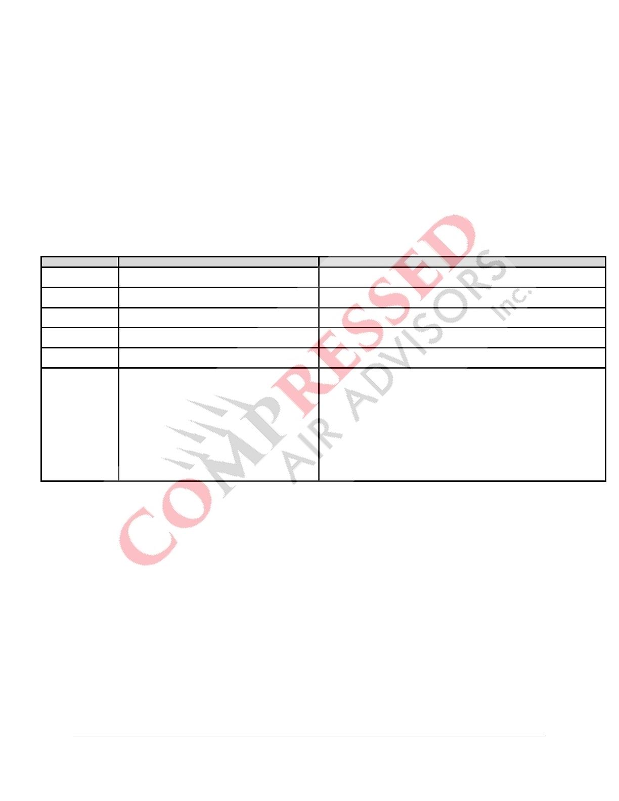
COMPONENT STANDARD WARRANTY COVERAGE DETAILS
Package
12 months from startup or 18 months from date of
shipment from Company, whichever occurs first
All components within the package (ie pressure switch, starter, etc),
excluding normal wear items
Pump Package
24 months from startup or 30 months from date of
shipment from Company, whichever occurs first
Applies to pump only, excludes head valves which are warranted for first
year only.
Pump Bare
12 months from startup or 18 months from date of
shipment from Company, whichever occurs first
Applies to pumps purchased as bares only
Electric Motors
12 months from startup or 18 months from date of
shipment from Company, whichever occurs first
For nonstandard motors, the original manufacturers warranty will take
precedence
Air Receivers
12 months from startup or 18 months from date of
shipment from Company, whichever occurs first
Recommended to be installed properly with Company vibration isolators
Labor
Package/Electric Motor/Air Receivers/Bare
Pumps: 12 months from startup or 18 months from
date of shipment from Company, whichever occurs
first
Pump (Package): 24 months from startup or 30
months from date of shipment from Company,
whichever occurs first
Service will be provided by Company representative or authorized service
personnel, for repair or replacement of any product or part which in the
Companys sole judgement is proved not to be as warranted. Labor shall be
limited to the amount specified in the Companys labor rate schedule. All
costs of transportation of product, parts, and repaired or replacement parts
claimed not to be as warranted to and from such service facilities shall be
borne by the Purchaser. The Company may require the return of any part
claimed not to be as warranted to one of its facilities as designated by
Company, to establish a claim under this warranty (Return freight eligible for
consideration for reimbursement). Replacement Parts provided under the
terms of the warranty are warranted for the remainder of the original
warranty period.
NO WARRANTY IS MADE WITH RESPECT TO:
1. Any product which has been repaired or altered in such a way, in the Companys sole judgement, as to affect the product adversely
2. Any product which has, in the Companys sole judgement been subject to negligence, accident, improper storage, or improper installation
or application
3. Any product which has not been operated or maintained in accordance with the recommendations of the company
4. Any reconditioned or prior owned product
5. Warranty is non-transferable
STANDARD WARRANTY DISCLAIMER
THE FOREGOING WARRANTY IS EXCLUSIVE AND IT IS EXPRESSLY AGREED THAT, EXCEPT AS TO TITLE, THE COMPANY
MAKES NO OTHER WARRANTIES AND HEREBY EXPRESSLY DISCLAIMS ALL OTHER WARRANTIES, INCLUDING WITHOUT
LIMITATION, EXPRESSED, IMPLIED OR STATUTORY WARRANTIES, INCLUDING ANY IMPLIED WARRANTY OF
MERCHANTABILITY OR FITNESS FOR A PARTICULAR USE. THE REMEDY PROVIDED UNDER THIS WARRANTY SHALL BE THE
SOLE, EXCLUSIVE AND ONLY REMEDY AVAILABLE TO PURCHASER AND IN NO CASE SHALL THE COMPANY BE SUBJECT TO
ANY OTHER OBLIGATIONS OR LIABILITIES. UNDER NO CIRCUMSTANCES SHALL THE COMPANY BE LIABLE FOR SPECIAL,
INDIRECT, INCIDENTAL OR CONSEQUENTIAL DAMAGES, EXPENSES, LOSSES OR DELAYS HOWSOEVER CAUSED. NO
STATEMENT, REPRESENTATION, AGREEMENT, OR UNDERSTANDING, ORAL OR WRITTEN, MADE BY ANY AGENT,
DISTRIBUTOR, REPRESENTATIVE, OR EMPLOYEE OF THE COMPANY WHICH IS NOT CONTAINED IN THIS WARRANTY WILL BE
BINDING UPON THE COMPANY UNLESS MADE IN WRITING AND EXECUTED BY AN OFFICER OF THE COMPANY. THIS
WARRANTY SHALL NOT BE EFFECTIVE AS TO ANY CLAIM WHICH IS NOT PRESENTED WITHIN 30 DAYS AFTER THE DATE UPON
WHICH THE PRODUCT IS CLAIMED NOT TO HAVE BEEN AS WARRANTED. ANY ACTION FOR BREACH OF THIS WARRANTY
MUST BE COMMENCED WITHIN ONE YEAR AFTER THE DATE UPON WHICH THE CAUSE OF ACTION OCCURRED. ANY
ADJUSTMENT MADE PURSUANT TO THIS WARRANTY SHALL NOT BE CONSTRUED AS AN ADMISSION BY THE COMPANY THAT
ANY PRODUCT WAS NOT AS WARRANTED. WARRANTY IS NOT TRANSFERRABLE.
R
-Series Electric 5 CQF3473 v.01
Operation & Service April 17, 2018
Safety and Operation Precautions
Because an air compressor is a piece of machinery with moving and rotating parts, the same precautions should be
observed as with any piece of machinery of this type where carelessness in operation or maintenance is hazardous
to personnel. In addition to the many obvious safety rules that should be followed with this type of machinery, the
additional safety precautions as listed below must be observed:
1. Read all instructions completely before operating air compressor or unit.
2. For installation, follow all local electrical and safety codes, as well as the National Electrical Code (NEC) an
d
the
Occupational Safety and Health Act (OSHA).
3. Electric motors must be securely and adequately grounded. This can be accomplished by wiring with a
grounded, metal-clad raceway system to the starter; by using a separate ground wire connected to the bar
e
m
etal of the motor frame or other suitable means.
4. Protect the power cable from coming in contact with sharp objects. Do not kink power cable and never allow
the
cable to come in contact with oil, grease, hot surfaces, or chemicals.
5. Make certain that the power source conforms to the requirements of your equipment.
6. Pull main electrical disconnect switch and disconnect any separate control lines, if used, before attempting to
work or perform maintenance on the air compressor or unit. "Lock out" or "Tag out" all power sources.
7. Do not attempt to remove any compressor parts without first relieving the entire system of pressure.
8. Do not attempt to service any part while machine is in an operational mode.
9. Do not operate the compressor at pressures in excess of its rating.
10. Do not operate compressor at speeds in excess of its rating.
11. Periodically check all safety devices for proper operation. Do not change pressure setting or restric
t
oper
ation in any way.
12. Be sure no tools, rags, or loose parts are left on the compressor or drive parts.
13. Do not use flammable solvents for cleaning the air inlet filter or element and other parts.
14. Exercise cleanliness during maintenance and when making repairs. Keep dirt away from parts by covering
parts and exposed openings with clean cloth or Kraft paper.
15. Do not operate the compressor without guards, shields and screens in place.
16. Do not install a shut-off valve in the discharge line, unless a pressure relief valve, of proper design and size, is
installed in the line between the compressor unit and shut-off valve.
17. Do not operate compressor in areas where there is a possibility of ingesting flammable or toxic fumes.
18. Be careful when touching the exterior of a recently run motor - it may be hot enough to be painful or cause
injury. With modern motors this condition is normal if operated at rated load - modern motors are built to
operate at higher temperatures.
19. Inspect unit daily to observe and correct any unsafe operating conditions found.
20. Do not "play around" with compressed air nor direct air stream at body. This can cause injuries.
21. Compressed air from this machine absolutely must not be used for food processing or breathing air withou
t
adequate
downstream filters, purifiers and controls.
22. Always use an air pressure regulating device at the point of use. Do not use air pressure greater than marked
maximum pressure of attachment.
23. Check hoses for weak or worn condition before each use and make certain that all connections are secure.
24. Always wear safety glasses when using compressed air gun.
The user of any air compressor package manufactured by Champion A Gardner Denver Co., is hereby warned
that failure to follow the preceding Safety and Operation Precautions can result in injuries or equipment damage.
However, Champion A Gardner Denver Co., does not state as fact or does not mean to imply that the preceding
list of Safety and Operating Precautions is all inclusive, and further that the observance of this list will prevent all
injuries or equipment damage.
R-Series Electric 6 CQF3473 v.01
Operation & Service April 17, 2018
Explanation of Safety Instructions, Symbols, and Decals
Indicates immediate
hazards which will result in severe injury or death.
Indicates hazards or unsafe practice which could result in damage to the Champion compressor or
minor injury.
NOTICE
Notice is used to notify people of installation, operation, or maintenance information which is
important but not hazard related.
Safety and Operation Precautions
OBSERVE, UNDERSTAND, AND RETAIN THE INFORMATION GIVEN IN THE SAFETY PRECAUTION
DECALS AS SHOWN IN THE DECAL LIST SECTION.
This Oil
-
Lubricated
Compressor must not be used for breathing air without adequate downstream
filters, purifiers, and controls. To do so will cause serious injury whether air is supplied direct from
the compressor source or to breathing tanks for later use. Any and all liabilities for damage or loss
due to injuries, death and/or property damage including consequential damages stemming from
the use of this compressor to supply breathing air will be disclaimed by the manufacturer.
The use of this compressor as a booster
pump and/or to compress a medium other than
atmospheric air is strictly non-approved and can result in equipment damage and/or injury. Non-
approved uses will also void warranty.
This unit may be equipped with special options which may not be included
in this manual. User
must read, understand, and retain all information sent with special options.
R
-Series Electric 7 CQF3473 v.01
Operation & Service April 17, 2018
Unit Hazard Decal List See Page 8
PART NO.
DESCRIPTION
P10157A
PRODUCT LIABILITY DECAL SHEET
-
MASTER
1
Unit Pressure Setting
2
NOT USED
3
DANGER
Breathing Air
4
DANGER
Drain Tank Daily
5
WARNING
Pressure/Safety Valve
6
NOT USED
7
DANGER
Valve Maintenance
8
DANGER
High Voltage
9
WARNING
Hot Surfaces
10
WARNING
Do Not Remove Fan Guard
11a
NOTICE
-
Lubricant
11b
NOT
USED
12
DECAL
Synthetic or Food Grade Inserts
13
NOT USED
14
DECAL
Pressure Setting: 95
-
125 PSIG
14
DECAL
Pressure Setting: 140
-
175 PSIG
15
NOTICE
Read and Retain Manuals
16
NOT USED
17
DECAL
Rotation Direction
18
NOT USED
P14677A
DECAL
Pressure Switch
Pump Hazard Decal List See Page 9
PART NO.
DESCRIPTION
P13805A
PUMP DECAL SHEET
MASTER
A1
NOT USED
A2
NOTICE
-
Lubricants
B
DECAL
Rotation Direction
C
NOTICE
Read and Retain Manuals
D
DANGER
Breathing Air
E
DECAL
Made in the United States of America
F
IMPORTANT NOTICE
Motor Burn
-
Outs
P14677A
R-Series Electric 8 CQF3473 v.01
Operation & Service April 17, 2018
Unit Hazard Decals
R-Series Electric 9 CQF3473 v.01
Operation & Service April 17, 2018
Pump Hazard Decals
F
R
-Series Electric 10 CQF3473 v.01
Operation & Service April 17, 2018
Installation
Do not operate unit if damaged during shipping, handling or use. Operating unit if damaged may
result in injury.
1
. Permanently installed compressors must be located in a clean, well ventilated dry room
so
c
ompressor receives adequate supply of fresh, clean, cool, and dry air. It is recommended that
a
c
ompressor, used for painting, be located in a separate room from that area wherein body sanding
and painting is done. Abrasive particles or paint, found to have clogged the air intake filters
and
intake valves, shall automatically void warranty.
2. Compressors should never be located so close to a wall or other obstruction that flow of air throug
h
t
he fan-bladed flywheel, which cools the compressor, is impeded. Permanently mounted unit
s
shoul
d be installed so that the belt guard is at least 12" from wall.
3. Place stationary compressors on firm level ground or flooring. Permanent installations are requi
red
to be anchored to floor. Bolt holes are provided in the air receiver or base feet. Use shims to level
the compressor unit. It is recommended that optional vibration isolator pads be installed with the
unit. Tanks anchored directly to a concrete floor without vibration isolator pads will not
be
warrant
ed against cracking. Champion vibration isolator pads must be used for extended warranty
to apply to ASME air receivers. See Air Receiver Installation section.
D
o not tighten the
anchor
screws/nuts down completely
this will result in undesirable stress on
the tank foot. This can cause abnormal vibration and possible cracking of the air receiver, resulting
in injury or equipment damage.
4
. If installing a bare pump or a base-mounted unit, make certain the system has adequate
pressure
l
imiting controls. Controls could be a pressure switch for start/stop operation or a pilot valve
for
c
ontinuous operation. If a pilot valve is used, the compressor must be equipped with
head
unl
oaders. Control air must be piped from the air receiver to the pilot valve.
5. A properly sized air check valve must be installed in the discharge piping, between the c
ompressor
out
let and the inlet of any receiver tank(s) in the system.
Do not install isolating valves between compressor outlet and air receiver. This will cause excessive
pressure if valve is closed, and cause injury and equipment damage.
R
-Series Electric 11 CQF3473 v.01
Operation & Service April 17, 2018
Installation (continued)
Always use an air pressure regulating device at the point of use. Failure to do so can result in injury
or equipment damage.
Do not install in an area
where ambient temperature is below 32
°
F or above 10
F.
Do not install unit in an area where air is dirty and/or chemical laden.
Unit is not to be installed outdoors.
E
LECTRICAL POWER SUPPLY
It is essential that the power supply and the supply wiring are adequately sized and that the voltage
corresponds to the unit specifications. Branch circuit protection must be provided at installation as
specified in the National Electrical Code.
All wiring should be performed by a licensed electrician or electrical contractor. Wiring must meet
applicable codes for area of installation. The table gives recommended wire sizes based on the 2017
NEC.
WIRE SIZE (AWG) - 75°C COPPER - 40°C AMBIENT
MOTOR
HP
3 PHASE
1 PHASE
200/208V
230V
460V
575V
115V
208V
230V
2
14 (1
2
)
14 (1
2
)
14 (14)
14 (14)
8 (
4
)
12 (
8
)
12 (10)
3
1
2
(10)
14 (1
0
)
14 (14)
14 (14)
6
(
3
)
10 (
6
)
10 (8)
5
10 (
6
)
12 (8)
14 (12)
14 (12)
--
8 (
4
)
8 (
4
)
7
-
1/2
8 (
4
)
10 (6)
14 (10)
14 (10)
--
4
(
1
)
6 (
2
)
10
8 (
3
)
8 (4)
12 (8)
14 (10)
--
--
--
15
4
(
1
)
6 (
2
)
10 (6)
10 (6
)
--
--
--
20
3 (
0
0)
4 (
0
)
8 (
4
)
10 (6)
--
--
--
25
1 (00
0
0)
2 (0
0
0)
6 (
3
)
8 (
4
)
--
--
--
30
0 (
250
)
1 (0
0
00)
6 (
2
)
8 (4)
--
--
--
Val
ues in ( ) for Duplex Unit w/one incoming power line to both motors.
All models require a properly sized magnetic starter as specified in the National Electric Code (NEC).
See Control Panel Manual for details.
If ordered with a factory mounted control panel, compressor is wired at factory. It is necessary only to
bring lines from a properly sized disconnect switch to the control panel mounted on the unit.
R
-Series Electric 12 CQF3473 v.01
Operation & Service April 17, 2018
Installation (continued)
Wiring must be such that when viewing compressor from opposite shaft end, rotation of shaft is
clockwise as shown by arrow on guard. Wrong direction rotation for any length of time will result
in damage to compressor.
GROUNDI
NG INSTRUCTIONS
This product should be connected to a grounded, metallic, permanent wiring system, or an equipment-
grounding terminal or lead on the product.
AIR LINE PIPING
C
onnection to air system should be of the same size, or larger, than discharge pipe out of unit. The table
gives recommended minimum pipe sizes. A union connection to the unit and water drop leg is
recommended. Install a flexible connector between the discharge of the unit and the plant air piping.
Plant air piping should be periodically inspected for leaks using a soap and water solution for detection
on all pipe joints. Air leaks waste energy and are expensive.
Minimum Pipe Sizes For Compressor Air Lines
(Based on clean Smooth Schedule 40 Pipe)
MODEL
25
50
100
200
300
R10D
3/4
(1)
3/4
(1)
3/4
(1)
3/4
(1)
3/4
(1)
R15B
3/4
(1)
3/4
(1)
3/4
(1)
1
(1
-
1/4)
1
(1
-
1/4)
R30D
3/4
(1
-
1/4)
1
(1
-
1/4)
1
(1
-
1/4)
1
(1
-
1/2)
1
(1
-
1/2)
R40A
1
-
1/4
(1
-
1/2)
1
-
1/4
(1
-
1/2)
1
-
1/4
(1
-
1/2)
1
-
1/4
(1
-
1/2)
1
-
1/4
(1
-
1/2)
R70A
1
-
1/4
(1
-
1/2)
1
-
1/4
(1
-
1/2)
1
-
1/4
(1
-
1/2)
1
-
1/2
(2)
1
-
1/2
(2)
Val
ues in ( ) are for duplex unit.
Never use plastic pipe or improperly rated metal pipe. Improper piping material can burst and cause
injury or property damage.
R
-Series Electric 13 CQF3473 v.01
Operation & Service April 17, 2018
Air Receiver Installation
Vi
bration isolator pads can be purchased from your local authorized distributor. Installation hardware
items (studs, screws, nuts, shims) are not provided. It is the compressor owners responsibility to
provide a suitable foundation and isolator installation.
D
o not tighten the
anchor
screws/nuts down completely
this will result in undesirable stress on
the tank foot. This can cause abnormal vibration and possible cracking of the air receiver, resulting
in injury or equipment damage.
TEN011442
-
00
(Ref. Drawing)
CUT
-
AWAY VIEW OF
ANCHORED
INSTALLATION
R
-Series Electric 14 CQF3473 v.01
Operation & Service April 17, 2018
Operation
This compressor has been inspected, thoroughly tested and approved at the factory. For this unit to
give long satisfactory service it must be installed and operated properly. This compressor has been
designed for an 80%/ON 20%/OFF duty cycle.
SIMPLEX UNITS have a pressure switch that senses changes in receiver pressure and automatically starts
and stops the compressor at preset pressure limits. If the receiver pressure falls below the cut-in
pressure setting of the pressure switch the compressor will run until the cut-out pressure setting of the
pressure switch has been reached.
DUPLEX UNITS have lead (PS1) and lag (PS2) pressure switches and an automatic alternating system to
evenly distribute the load between the two compressors. The pressure switches sense changes in
receiver pressure and automatically start and stop the compressor at preset pressure levels. If the
receiver pressure falls below the cut-in pressure setting of the lead (PS1) pressure switch but remains
above the cut-in pressure setting of the lag (PS2) pressure switch, only one compressor will run until
receiver pressure reaches the cut-out pressure of the lead (PS1) pressure switch. The next time the
pressure in the receiver drops, the system automatically starts the compressor that was idle. If the
receiver pressure falls below the cut-in pressure setting of the lag (PS2) pressure switch, both
compressors run until receiver pressure reaches the cut-out pressure setting of the lead (PS1) pressure
switch.
CONTINUOUS RUN units are equipped with a ball valve, pilot valve and head unloaders to provide
continuous run capabilities. The pilot valve acts as an automatic air switch allowing air to flow from the
receiver to the head unloader mechanism, thus actuating it. To operate unit in continuous run, open
ball valve located next to pilot valve. The pilot valve is now able to sense receiver pressure. When the
receiver pressure reaches the cut-out pressure setting of the pilot valve, the pilot valve opens and air is
released to the unloader mechanism. The compressor stops compressing air and runs unloaded until
the cut-in pressure setting of the pilot valve has been reached. At this time air released from the
unloader mechanism and the compressor starts compressing again. Continuous run is recommended if
motor starts exceed 8 starts/hour.
INITIAL START UP ELECTRIC MOTOR UNITS
1. Inspect unit for any visible signs of damage that would have occurred in shipment or during
installation.
2. Pull main disconnect switch to unit to assure that no power is coming into the unit. Lock Out
or
T
ag Out switch. Connect power leads to start.
Do not attempt to operate compressor on voltage other than that specified on order or on
compressor motor and control panel. Voltage conversion kits are available if alternate operating
voltage is required.
R
-Series Electric 15 CQF3473 v.01
Operation & Service April 17, 2018
Operation (continued)
3. Check compressor oil level. Add oil as required. See Compressor Oil Specifications Section.
NOTE: Do not mix oil type, weights, or brands.
4. Activate main disconnect switch.
5. Jog motor and check for proper rotation by direction arrow. If rotation is wrong, reverse input
connections on the magnetic starter.
6. Close receiver discharge ball valve and start the compressor.
7. With receiver ball valve closed, let the machine pump up to operating pressure.
8. Check for proper operation of the pressure switch.
a. When the air receiver pressure reaches the cut-out setting of the pressure switch, t
he
mac
hine will stop.
b. Open the receiver ball valve slowly, allowing pressure in the receiver to drop.
c. When the air receiver pressure drops to the cut-in setting of the pressure switch, t
he
mac
hine will start.
d. Repeat steps a. thru c. three times.
9. Check for proper operation of the head unloaders (if equipped).
a. Open the ball valve located next to the pilot valve.
b. When the air receiver pressure reaches the cut-in setting of the pilot valve, the
head
unloaders will activate. The air compressor continues to run, but air compression is stopped.
c. Open the receiver ball valve slowly, allowing pressure in the receiver to drop.
d. When the air receiver pressure drops to the cut-out setting of the pilot valve, the head
unloaders will de-activate. Air compression will resume.
e. Repeat steps b. thru d. three times.
10. Check for proper operation of any options.
11. When the initial run period has shown no operating problems, shut unit down and recheck oil level.
12. Open receiver ball valve. The air compressor unit is now ready for use.
This unit can start automatically without warning.
R
-Series Electric 16 CQF3473 v.01
Operation & Service April 17, 2018
Low Oil Shutdown Control
(optional equipment)
The oil monitor must be used in conjunction with a magnetic starter (see wiring diagram for details).
The oil monitor is installed on the outside of the air compressor crankcase with a port that allows oil
to feed into its float bowl chamber and maintain the same level as in the crankcase. The float moves
vertically up or down as the oil level changes. If the oil level is below minimum allowable operating
level, the reed switch will open, thus stopping the motor. A magnet holds the float and prevents the
compressor from starting. In order to start the compressor the following steps must be taken:
1. Fill crankcase to recommended capacity as indicated when level reaches the middle of the oil
sight glass.
2. Turn cam reset knob 90° clockwise.
IMPORTANT NOTE: The Oil Monitor does not eliminate the compressor owner's responsibility for
periodically checking oil level. Refer to maintenance instructions.
WIRING DIAGRAM: The oil monitor is wired into the control panel as shown below. Refer to the
Control Panel User Manual for complete wiring diagrams.
C509
-
A
(Ref. Drawing)
Remove jumper between 5 & 6
343CAS546
(Ref. Drawing)
R
-Series Electric 17 CQF3473 v.01
Operation & Service April 17, 2018
Low Oil Shutdown Control (continued)
(optional equipment)
TROUBLESHOOTING & SERVICING
Always disconnect unit from power supply and relieve all pressure from air tank before
performing any maintenance. Lock Out or Tag Out all power sources. Failure to do so
may result in personal injury or death.
NOTICE
Do not disassemble LOSC switch. Disassembly will void warranty.
N
o adjustments are required for the oil monitor.
If the oil monitor does not operate properly, check the items listed below to determine the cause.
1. Crankcase Oil
a. Check sight glass to insure proper oil level in crankcase, when compressor is shut off.
b. Check crankcase oil for proper viscosity. This is particularly important for temperat
ure
c
onditions below 32˚F. Oil which is too thick can slow the response of the mechanism,
causing float to register a low level.
c. Change oil regularly. Clean oil insures proper operation of the Oil Monitor, as well
as
c
ompressor. See Compressor Oil Specification and Maintenance sections for details.
2. Vent T
ube
a. C
heck vent tube to insure it is not clogged.
b. Check the gasket between valve body and bowl for leaks. This will cause a pressure rise i
n
t
he crankcase which will give a false safe oil level indication.
c. Check the fittings at ends of vent tube for tightness and leaks.
3.
Reset
a. C
heck that reset return spring is in proper working order.
b. Verify that reset knob is in fully counterclockwise position.
R
-Series Electric 18 CQF3473 v.01
Operation & Service April 17, 2018
Compressor Oil Specifications
C
ompressors are factory filled with CHAMPLUB hydrocarbon-based recip lubricant. This is an ISO 100
non-detergent industrial lubricant with rust and oxidation inhibitors specially formulated for
reciprocating compressors. It is recommended this compressor be maintained using this oil for ambient
temperatures above 32°F.
CHAMPLUB synthetic is a premium grade diester based synthetic lubricant providing excellent
performance in high temperature applications.
Do not mix oil types, weights or brands.
Emulsification of oil (white milky substance) indicates unsafe accumulation of moisture and may
be evidence compressor is oversized for application. Failure to promptly consult your local
distributor, or Champion Customer Service, can be grounds to deny warranty.
L
UBRICANT - ISO 100 MINERAL
CHAMPLUB
ISO 100
DESCRIPTION
PART NUMBER
1
Quart Case (12/case)
P09479A
1
Gallon Case (4/case)
P08909A
5
Gallon Pail
P08908A
55
Gallon Drum
P08907A
LUBRICANT - SYNTHETIC DIESTER
CHAMPLUB
SYNTHETIC
DESCRIPTION
PART NUMBER
1
Quart Case (12/case)
P13179A
1
Gallon Case (4/case)
P13180A
5
Gallon Pail
P11506A
55
Gallon Drum
P13181A
R
-Series Electric 19 CQF3473 v.01
Operation & Service April 17, 2018
Compressor Oil Specifications (continued)
LUBRICANT LEVEL:
BREAK-IN PERIOD: 100 hours of operation or 3 months, whichever comes first.
1. Compressor must run for the break-in period using CHAMPLUB ISO 100 lubricant.
2. During the break-in period, a careful and regular check of the oil level should be made. Maintai
n
oi
l level at the full line.
3. After the break-in period, thoroughly drain existing oil from crankcase.
4. Add a full charge of CHAMPLUB ISO 100 lubricant.
CHANGING TO SYNTHETIC DIESTER BASED LUBRICANT
If changing to synthetic lubricant, the following steps must be completed.
1. Compressor must run for the break-in period using CHAMPLUB ISO 100 lubricant.
2. During the break-in period, a careful and regular check of the oil level should be made. Maintai
n
oi
l level at the full line.
3. After the break-in period, thoroughly drain existing oil from crankcase.
4. Add a full charge of CHAMPLUB SYNTHETIC lubricant.
5. Run compressor for 200 hours.
6. Stop compressor and thoroughly drain the synthetic lubricant.
7. Add a full charge of CHAMPLUB SYNTHETIC lubricant.
8. Compressor is now ready to run for extended period before next lubricant change. Maintain oil
level at the full line.
Maintain lubricant level
at center of sight glass
R-Series Electric 20 CQF3473 v.01
Operation & Service April 17, 2018
Guide to Maintenance
To obtain reliable and satisfactory service, this unit requires a consistent preventive maintenance
schedule. Maintenance schedule pages are included in the back of this manual to aid in keeping the
proper records.
Before performing any maintenance function, switch main disconnect switch to "off" position to
assure no power is entering unit. "Lock Out" or "Tag Out" all sources of power. Be sure all air
pressure in unit is relieved. Failure to do this may result in injury or equipment damage.
Do not exceed 15 PSIG nozzle pressure when cleaning element parts with compressed air. Do not
direct compressed air against human skin. Serious injury could result. Never wash elements in fuel
oil, gasoline or flammable solvent.
Never operate unit without belt guard in place. Removal will expose rotating parts which can cause
injury or equipment damage.
Valves must be reinstalled in original position. Valve gaskets should be replaced each time valves
are serviced.
PRESSURE RELIEF VALVE: The pressure relief valve is an automatic pop valve. Each valve is properly
adjusted for the maximum pressure permitted by tank specifications and working pressure of the
unit on which it is installed. If it should pop, it will be necessary to drain all the air out of the tank in
order to reseat properly. Do not adjust.
TANK DRAIN VALVE: Drain valve is located at bottom of tank. Open drain valve daily to drain
condensation. Do not open drain valve if tank pressure exceeds 25 PSIG. The electric tank drain-
equipped compressor requires draining manually once a week.
PRESSURE SWITCH: The pressure switch is automatic and will start compressor at low pressure and
stop when the maximum pressure is reached. It is adjusted to start and stop compressor at the
proper pressure for the unit on which it is installed. Only a certified field service technician should
make adjustments to the pressure switch.
  • Page 1 1
  • Page 2 2
  • Page 3 3
  • Page 4 4
  • Page 5 5
  • Page 6 6
  • Page 7 7
  • Page 8 8
  • Page 9 9
  • Page 10 10
  • Page 11 11
  • Page 12 12
  • Page 13 13
  • Page 14 14
  • Page 15 15
  • Page 16 16
  • Page 17 17
  • Page 18 18
  • Page 19 19
  • Page 20 20
  • Page 21 21
  • Page 22 22
  • Page 23 23
  • Page 24 24
  • Page 25 25
  • Page 26 26
  • Page 27 27
  • Page 28 28
  • Page 29 29
  • Page 30 30
  • Page 31 31
  • Page 32 32

Champion R70A Operation & Service Manual

Category
Air compressors
Type
Operation & Service Manual
This manual is also suitable for

Ask a question and I''ll find the answer in the document

Finding information in a document is now easier with AI