Page is loading ...

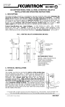
Installation Instructions:
1. If the ADB is to be installed in a semi-mortise, prepare door according to the dimensions shown in the profile drawing on front of label.
NOTE: If a door is fire labeled or of acoustical construction, semi-mortise preparation must be done by the door manufacturer or licensed machiner only.
2. Cut from end opposite actuating plunger only.
3. DO NOT cut off more than two (2) inches.
4. When cutting, be sure that the drop bar is flush with the case on the plunger side and that the gasketing insert projects at least 1/8”.
• For semi-mortise installation, cut ADB to door width.
• For surface mounted installation, cut ADB 1/8” less than the distance between the stops.
5. Adjust and trim the gasketing insert so that it projects at least 1/16” at each end of the drop bar and case.
6. For nylon brush seal ADB’s, use bolt cutters or diagonal cutting pliers that will pinch the strip to retain the bristles (as shown in Figure 1).
7. Crimp the ends of the brush strip and drop bar to prevent the nylon brush from sliding (as shown in Figure 2).
8. With the actuating plunger at the hinge side, fasten the ADB to the door bottom with the screws provided, these Type AB screws will accommodate
hollow metal and wood doors.
9. For surface mounted installation, the plunger contacts the stop (as shown in Figure 3).
10. For semi-mortise mounted installation, the plunger contacts the rabbet (as shown in Figure 4).
11. The underside edge of the ADB case should be installed flush with the bottom of the door.
12. For wood jambs, a #10 x 1/2” flat head screw is furnished for installation at the point where the plunger contacts the jamb to prevent indenting.
13. Screw the actuating plunger in or out as required until the gasketing insert just touches the sealing surface when the door is closed.
14. It is only necessary to lightly compress the insert against the sealing surface to provide a good seal.
15. Further adjustments may be required for uneven surfaces.
Figure 1
Figure 2
Figure 3 - Surface Mounted
Figure 4 - Semi-Mortise Mounted

End Plate Installation Instructions:
End Plate
1. The automatic door bottom must be correctly installed and adjusted in
accordance with the installation instructions furnished with this product
(see other side).
2. Be sure that the drop bar (part that contains the seal) does not project
beyond the end of the case when the actuation plunger is depressed (as
shown in Figure 7). If it does project beyond the case, it was improperly
trimmed in the field. This condition can be corrected by removing the unit
and trimming the excess.
NOTE: Under no condition should the insert project beyond the edge of
the case.
Figure 7 - Improper Drop Bar
This shows an improper drop
bar protruding from the end of
the case. The drop bar should be
flush at both ends.
Drop Bar
Figure 8 - Properly Installed End Plate
This shows a properly installed
end plate. Do not use power tool
to tighten this screw.
End Plate
Figure 5 - Plunger End Plate
Figure 6 - End Plate
3. Insert the No. 10 x 1/2” flat head screw into the central opening of the endplate and tighten with a small Phillips
screwdriver. Insert the end plate into the case at the lock edge side of the door. Power drivers are not suggested
as they may over-tighten the screw and possibly break the end plate (as shown in Figure 8).
4. Next insert the plunger end plate with the hexagon hole. This pushes straight in. It also serves to prevent the
plunger from rotating and changing adjustment (as shown in Figure 9 and Figure 10). If this end plate needs to
be removed for readjustment, it can be removed in two ways: (1) push the drop bar towards the hinge side of the
door and it will eject the end plate; (2) prying at the top of the end plate with a knife or other tool. Do not pry at
the bottom. This will cause it to break.
Figure 9
Plunger end plate prevents
the plunger adjustment from
rotating.
End Plate
Plunger
Plunger
Figure 10
Plunger end plate installed.
PLEASE READ THESE INSTRUCTIONS THOROUGHLY BEFORE ATTEMPTING TO INSTALL END PLATES.
IMPORTANT! These parts are made from glass filled nylon. They are very strong, but brittle. Do not attempt to twist or
bend them or they will break. This is not a problem if properly installed or removed.
/