Acson IM-WSS-0706-ACSON Installation guide
- Category
- Split-system air conditioners
- Type
- Installation guide

WATER COOLED SPLIT TYPE
AIR CONDITIONER
WATER COOLED
INSTALLATION MANUAL
Model: IM-WSS-0706-ACSON
Part Number: R08019028461

1
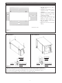
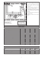
OUTLINE AND DIMENSIONS
1. WSS 10/15/20/25 A
2. WSS30/40/50/60 A
700.0
572.096.0
32.0
317.0
357.0
774.0
A
DC
60.0
B
280.0
61.5
70.0
Model 10/15 20/25
(WSS) A A
A 330.0 360.0
(13.0) (14.2)
B 55.0 55.0
(2.2) (2.2)
C 70.0 70.0
(2.8) (2.8)
D 61.5 61.5
(2.4) (2.4)
All dimensions in mm
Model (WSS) A B C D E F G H I J K L M N O
30A 780 152 556 72 380 418.5 844 385 320 130 61.5 94 80 60 62
(30.7) (6.0) 21.9) (2.8) (15.0) (16.5) (33.2) (15.2) (12.6) (5.1) (2.4) (3.7) (3.1) (2.4) (2.4)
40A 920 151 692 77 511 549.5 1020 440 450 130 61.5 102 100 80 75
(36.2) (5.9) (27.2) (3.0) (20.1) (21.6) (40.2) (17.3) (17.7) (5.1) (2.4) (4.0) (3.9) (3.1) (3.0)
50/60A 920 162 682 76 610 648.5 1020 504 550 130 61.5 107 100 80 75
(36.2) (6.4) (26.9) (3.0) (24.0) (25.5) (40.2) (19.8) (21.7) (5.1) (2.4) (4.2) (3.9) (3.1) (3.0)
A
C
B
D
E
F
H
G
ON M L
I
K
J
All dimensions in mm
Figure 2
Figure 1

2
INSTALLATION LOCATION
All dimensions in mm
Figure 3
WSS 10/15/20/25 A WSS 30/40/50/60 A
WASHER
HEX. NUT
VIBRATION ISOLATOR
HEX. NUT
THREADED ROD
WASHER
WASHER
HEX. NUT
VIBRATION ISOLATOR
HEX. NUT
THREADED ROD
WASHER
Figure 4
• This unit will be mounted on the ceiling by the support of four threaded rods. (Refer to Figure 4)
• Ensure that the supports are strong enough and properly anchored to withstand the weight of the unit.
• Use isolator rubber (natural rubber) with hardness of 35º for better noise and vibration control.
• Do not locate the drainage system at any point above the drain connection.
• The unit is designed for indoor
installation only.
• Installation work should be done by
authorized dealer or qualified
contractor.
• Install the unit at a suitable minimum
distance or shortest path to the
coupling fan coil unit.
• There should be sufficient space for
piping connection, service and
maintenance. (Refer to Figure 3)
• The area should be isolated from
vibration and noise.
• Ensure the area is free from water
leakage.
800
500
800
1200

3
! CAUTION
Please take note of the following important points when installing.
• Do not install the unit where leakage of flammable gas may occur.
If gas leaks and accumulates around the unit, it may cause fire ignition.
• Do not overcharge the unit.
This unit is factory pre-charged. Overcharge will cause over-current or
damage to the compressor.
• Ensure the rated voltage and phase of the unit corresponds to the unit name
plate before carrying out wiring work.
• The unit must be GROUNDED to prevent hazards due to insulation failures.
• Do not ground any electrical equipment to the water piping.
• Ensure all electrical wiring do not touch the refrigerant piping, compressor,
pump or any moving parts.
• Do not operate unit with wet hand(s). It will result in electrical shock.
• Ensure there is water supply into the unit at all times before operating.
• Do not attempt to so any service or maintenance when the unit is operating.
• Unauthorized modification of the unit is not allowed.
SAFETY PRECAUTIONS
! WARNING
• Installation and maintenance should
be performed by qualified persons
who are familiar with local code and
regulation, and experienced with this
type of appliance.
Figure 5
BALANCING VALVE
1
2
3
4
5
1: SHUT OFF VALVE
2: WATER OUT
3: WATER IN
4: Y-STRAINER
5: SHUT OFF VALVE
6: FLEXIBLE HOSE
ENSURE WATER VALVE ADAPTORS
ARE ALIGNED TO THE CENTER
WITHOUT TOUCHING
(min 2mm) THE RUBBER BUSH
WHEN MAKING
PIPING CONNECTION.
Figure 6
Figure 7
RUBBER BUSH
6
2
3
1
1: VACUUM PUMP
2: LIQUID VALVE
3: GAS VALVE (3-WAY)
HANDLE
Lo
HANDLE
Hi
(ALWAYS CLOSED)

4
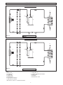
SCHEMATIC DIAGRAM
SCHEMATIC DIAGRAM
SCHEMATIC DIAGRAM
WSS 10/15/20/25 A
5
1
2
3
4
#
!
8
6
9
NOTE:
1. GAS PIPING 8: WATER OUTLET
2: FAN COIL UNIT 9: TUBE IN TUBE HEAT EXCHANGER
3: FAN MOTOR 10:WATER INLET
4: LIQUID PIPING 11:STRAINER
5: COMPRESSOR 12:COOLING CAP TUBE
6: HIGH PRESSURE SWITCH
7: LOW PRESSURE SWITCH
* FOR FIGURE 9, ITEM 11 & 12 ARE NOT AVAILABLE.
11
7
COOLING OPERATION
WSS 30/40/50/60 A
5
1
2
3
4
9
8
67
COOLING OPERATION
Figure 8
Figure 9
11
!

5
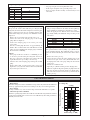
ELECTRICAL WIRING CONNECTION
WSS 10/15 A
WSS 20/25/30 A
PURPLE WHITE
BLUE BLUE
MAGNETIC
CONTACTOR
RED
RED
REDRED
BLUE
BLUE
BLACKBLACK
HP
LP
BLUE
RELAY
(O.R.)
PURPLE
PURPLE
BLACK
BLUE
BLUE
BLUE
GREEN/YELLOW
BLUE
RED
CM
S
RC
COMP N
( TO INDOOR UNIT)
OLP
PURPLE
BLUE
BLUE
BLACKBLACK
HP
LP
BLUE
BLUE
BLUE
RED
CM
S
RC
RELAY
(O.R.)
BLUE
GREEN/YELLOW
PURPLE
PURPLE
BLACK
BLUE
BLUE
COMP N
( TO INDOOR UNIT)
MAGNETIC
CONTACTOR
REDRED
REDRED
BLUE
Figure 10
Figure 11

6
PHYSICAL DATA
WSS 40/50/60 A
• Refer to the wiring diagram provided on
the unit when making electrical wiring
connection. (Refer to Figure 10, 11 & 12).
• Power supply is from fan coil unit
connection.
• All field wiring must comply with your
national or local wiring regulation.
• All terminal wiring must be firmly
connected. Improper connection can cause
electric shock, short circuit or fire
breakout.
• A circuit breaker must be provided for over
current protection.
• All safety precautions need to be strictly
adhere.
GREEN/YELLOW
BLUE
BLUE
RED
RED
RED
RED RED
HP
LP
WHITE WHITE
BLUE
BLUE
RED
BLUE
BLUE
BLUE
RELAY
A1 A2 A3 A4 N
RED
PP
NC
CDM
LNR ST
DT
ORANGE
ORANGE
COMPRESSOR
RED
WHITE
BLUE
RST
RED
WHITE
BLUE
CRANKCASE
HEATER
--- - FIELD SUPPLY WIRING
PP - PHASE PROTECTOR
HP - AUTO RESET HP SWITCH
LP - AUTO RESET LP SWITCH
NOTE:
1) WITH PHASE PROTECTOR
2) FOR LOCAL SPEC
3) FOR 380~415V/3PH/50Hz
4) WITH CRANKCASE HEATER
Model WSS10A WSS15A WSS20A WSS25A
Nominal Cooling Capacity kW 2.78 4.10 5.16 6.33
Unit Weight kg 35.4 39.4 39.5 40.5
Refrigerant Charge R22 kg 0.450 0.725 0.825 0.800
Compressor Rotary compressor
Refrigerant Circuit
Liquid valve connection inches 1/4 1/4 1/4 3/8
Gas valve connection inches 3/8 1/2 5/8 5/8
Service port connection (UNF-20) inches 7/16 7/16 7/16 7/16
Refrigerant - Water Heat Exchanger Tube in Tube
Water inlet (BSP) MALE inches 1/2 1/2 1/2 1/2
Water outlet (BSP) MALE inches 1/2 1/2 1/2 1/2
Nominal pressure drop kPa 18.5 24.5 30.9 49.7
Nominal flow rate m
3
/h 0.60 0.90 1.00 1.35
Drain Pipe Connection
Steel pipe inches 3/4 3/4 3/4 3/4
ELECTRICAL DATA
Model WSS10A WSS15A WSS20A WSS25A
Power Supply V/Ph/Hz 220 - 240 V / 1 Ph / 50 Hz
Nominal Power Input (Cooling) W 717 1103 1270 1658
Nominal Current (Cooling) A 3.3 5.3 5.8 7.6
Capacitor uF 25.0 uF 40.0 uF 45.0 uF 40.0 uF
Figure 12

7
RECOMMENDED CABLE SIZE
Model WSS10A WSS15A WSS20A WSS25A
Rated Voltage Range 220 - 240V / 1Ph / 50Hz
Recommended Fuse A15 15 20 20
Supply Cable Size mm
2
1.5 1.5 2.5 2.5
Number of Cables 3333
Interconnection Cable Size mm
2
1.5 1.5 2.5 2.5
Number of Cables 3333
REFRIGERANT PIPING WORK
1. Piping Length, Elevation and Bends
Model WSS10A WSS15A WSS20A WSS25A
Max. Length, L 12 12 15 15
Max. Elevation, H 5 5 5 5
Max. No. of bends 10 10 10 10
Liquid Valve Size 6.35mm 6.35mm 6.35mm 9.52mm
(1/4") (1/4") (1/4") (3/8")
Gas Valve Size 9.52mm 12.7mm 15.88mm 15.88mm
(3/8") (1/2") (5/8") (5/8")
• When piping length becomes too long, both
the capacity and compressor reliability drop.
• As the number of bends increases, system-
piping resistance to the refrigerant flow
increase thus lowering the capacity of the
unit and as a result the compressor may
become defective.
• Always choose the shortest path and follow
the recommendation as tabulated.
2. Water Piping and Fitting
• Install a 40-60 mesh strainer to ensure water quality is good.
• Water pipe materials recommended are black steel pipe and
copper pipe.
• All piping connections must be properly and firmly connected.
Do not over-tighten the connections.
• Users are recommended to install the pipes as shown in Figure
5 & 6.
• The piping need to be cleaned and flushed prior to operation.
• Air vents must be installed at the highest position while a
drainage system at the lowest position of the water circuit.
3. Refrigerant Piping
• Do not use contaminated, dented or used copper tubing.
• Do not use copper tubes with less than 0.8mm thickness.
• Cut the connection pipe with a pipe cutter.
• Remove burrs from cut edges of the pipes with remover. Hold
the end of the pipe downwards to prevent metal chips from
entering the pipe.
• Use proper torque wrench to tight the flare nuts. If the torque
strength is weak, gas leakage may occur. If it is too tight, the
flare nut may crack and it may be non-removable.
• Insulate the piping to prevent capacity losses and water.
4. Flare Work
HEAD PROJECTION DIMENSION
Diameter A(mm)
in mm Imperial Rigid
1/4 6.35 1.3 0.7
3/8 9.52 1.6 1.0
1/2 12.70 1.9 1.3
5/8 15.88 2.2 1.7
3/4 19.05 2.5 2.0
FLARE DIE
COPPER TUBE
COPPER TUBE
FLARE NUT
B
D
Diameter, D Flare End Diameter, B
in mm
1/4 6.35 9.1
3/8 9.52 13.2
1/2 12.70 16.6
5/8 15.88 19.7
3/4 19.05 24.0
• Head project dimension may
differ according to type of flare
tool.
• Flare section should be uniform
or even. Crack on the flare
section or burr on the flare edge
is not acceptable. Make new
flare tubing again to prevent
potential gas leak.
A

8
5. Tightening Torque
Diameter, D Torque (Nm)
in mm
1/4 6.35 18
3/8 9.52 42
1/2 12.70 55
5/8 15.88 65
3/4 19.05 78
• Use proper torque wrench to tight the flare nuts.
• If the torque strength is weak, gas leakage may occur.
• If it is too tight, the flare nut may crack and it may be non
removable.
VACUUMING AND CHARGING
1. Purging The Piping And The Indoor Unit
Except for the outdoor unit which is pre-charged with
refrigerant, the indoor unit and the refrigerant connection pipes
must be airpurged because the air containing moisture that
remains in the refrigerant cycle may cause malfunction of the
compressor.
• Remove the caps from the valve and the service port.
• Connect the center of the charging gauge to the vacuum
pump. (Refer to Figure 7)
• Connect the charging gauge to the service port of the
3-way valve.
• Start the vacuum pump. Evacuate for approximately 30
minutes. The evacuation time varies with different vacuum
pump capacity. Confirm that the charging gauge needle has
moved towards -760mmHg.
Caution:
• If the gauge needle does not move to -760mmHg, be sure
to check for gas leaks (using the refrigerant detector) at
flare type connection of the indoor and outdoor unit and
repair the leak before proceeding to the next step.
• Close the valve of the charging gauge and stop the vacuum
pump.
• On the outdoor unit, open the suction valve (3 way) and
liquid valve (2 way) (in anti-clockwise direction) with 4mm
key for hexagon sacked screw.
2. Additional Charge
• The pre-charged of R22 in the Water Cooled Split Type
unit is suitable for standard pipe of length up to 7.6m.
• When the piping is more than the above stated standard
pipe length, kindly add additional charge referring to the
table below.
Model Gram/Meter
WSS10A 30
WSS15A 30
WSS20A 30
WSS25A 30
3. Charge Operation
This operation must be done by using a gas cylinder and a
precise weighing machine. The additional charge is topped-
up into the outdoor unit using the suction valve via the service
port.
• Remove the service port cap.
• Connect the low pressure side of the charging gauge to the
suction service port center of the cylinder tank and close
the high pressure side of the gauge. Purge the air from the
service hose.
• Start the air conditioner unit.
• Open the gas cylinder and low pressure charging valve.
• When the required refrigerant quantity is pumped into the
unit, close the low pressure side and the gas cylinder valve.
• Disconnect the service hose form service port. Put back the
service port cap.
UNIT OPERATION LIMITS
1. Environment
This unit is designed for indoor installation and operation only. This unit also limited to
water loop application only as the heat exchanger can only cater for this application.
2. Power Supply
A voltage variation of +/– 10% of rated voltage stated in the unit label is acceptable.
3. Allowable Operation Conditions
Ensure the operating temperature and conditions are in allowable range. Extreme variations
in temperature, humidity and corrosive water or air will adversely affect unit performance,
reliability and service life.
Water Entering Temp. (
o
C)
45
30
13
STD
Cooling
15 19 24
Indoor Temp. (
o
C WB)
4. Cooling only

9
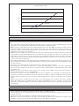
Graph pressure drop Vs flow rate
0.0
10.0
20.0
30.0
40.0
50.0
60.0
70.0
0.00 0.20 0.40 0.60 0.80 1.00 1.20 1.40 1.60 1.80
Flow rate, m
3
/hr
Pressure drop, kPa
WSS10A
WSS15/20/25A
6. Water Pressure Drop Graph
SYSTEM CLEANING AND FLUSHING
The water circulating loop system must be cleaned and flushed to remove all construction debris and dirt before operating the
units.
1. If the connection is equipped with water shut-off valve, either electric or pressure operated, the individual supply and return
pipes must be connected together first. This will prevent the introduction of dirt into the unit.
2. Fill the water loop system with your local water supply with all air vents open. After filling, close all air vents. The contractor
should start the main circulator pump with the pressure reducing valve open. Check all vents in sequence to bleed off any
trapped air, ensuring circulation through all components of the system. Power to the heat rejector unit should be off and the
supplementary heat control set at 27ºC (80ºF).
3. While the water is circulating, the contractor should check and repair any leaks in the piping. Drains at the lowest point(s) in the
system should be opened for initial flush and blow down. Make sure the local supply water valves are set to make up for the
required flow rate. Check the pressure gauge at the pump suction and manually adjust the make up to hold the same positive
steady pressure both before and after opening the drain valves. Flush should be continuously for two hours or longer if required
to obtain a clean and clear drain water.
4. Shut off all supplemental heater and circulator pump and open all drains and vents to complete drain down the system. Now, the
short-circuited water connection to the supply and return pipes should be removed and connected to the individual water inlet
and outlet of the unit.
Use proper tape to seal off at the valve connection. Do not use sealant at the valves connection.
5. Trisodium phosphate was formerly recommended as a cleaning agent during flushing. However, some of the local authorities
ban the usage of the phosphate into the sewage systems. The current recommendation is to simply flush longer with warm at
27ºC (80ºF) water.
6. Refill the water loop system with clean water. Test the water for acidity by using a litmus paper. Treat the water if required to
obtain the pH level between 7.5 to 8.5 (slightly alkaline).
7. Once the water system is ready, ensure at all times only clean water is supplied to the system. Dirty water will result in wide
degradation of performance and solids may clog valves, strainers, flow regulator, etc. Pump work will increase and may damage
the pumps. The heat exchanger may become clogged as well which will reduce the compressor service life or causes premature
failure.
8. Finally set the loop water controller heat rejection point to 29ºC (85ºF). Supply power to all motors and start the circulating
pumps. After full flow has been established through all components including heat rejectors (regardless of season) and air
vented and loop temperature stabilized, each of the air conditioner will be ready for check, test and start up, air balancing and
water balancing.
SERVICE AND MAINTENANCE
• Service and maintenance should be performed by authorized dealer or qualified contractor.
• Internal components can be accessed through two service panels (front and back). External control box for easy access of
electrical components.
• Regular checks on the water strainer are recommended. Clean the strainer if dirty or clogged.
• Maintenance a log data on measurement of volts, amps, and water temperature difference is recommended. A comparison of the
data during start-up and periodic data is useful as indicator of general condition of equipment.

10
Fault Cause/Check Point
Unit cannot start 1. Power supply plug disconnected.
2. Circuit breaker or fuse tripped / blown.
3. Wiring connection.
4. If fault persist, contact your installer.
Neither fan coil unit 1. The fuse may be blown or circuit breaker opened.
and compressor run 2. Check electrical circuit or motor winding for shorts or grounds. Investigate for possible over loading.
Replace fuse if necessary.
3. Check wiring connections. Wire may be loosening. Replace or tighten.
4. Control system may be faulty.
Compressor does 1. Check capacitor if available. Replace capacitor if faulty.
not operate 2. Check wiring connection. Wire may be loosening. Replace or tighten.
3. The high pressure switch may tripped due to:
a) No or insufficient water flows into and leaves heat exchanger. May be clogged.
b) Water entering temperature higher than the maximum operating conditions.
c) Not enough air flow into fan coil unit. May be due to dirty filter or block by object, cardboard and
etc (heating mode).
d) Fan coil motor failure (heating mode).
e) Unit over-charged. Release some of the refrigerant charge.
4. The compressor internal/external overload protection is opened. If the compressor body is extremely
hot, the overload will not reset until it cooled down.
5. The compressor winding may be grounded to the compressor shell. If so, replace the compressor.
Insufficient cooling 1. Check controller temperature setting.
2. Filter may be clogged. Check and clean the filter.
3. Check capillary tube for possible restriction of refrigerant flow. Replace capillary tube if proven so.
4. The reversing valve may be defective (valve position is not shifted properly), creating a bypass of
refrigerant. Check the reversing valve coil connection.
5. Check for restriction of air and water flow.
6. Refrigerant leakage. Check all piping bends and connection for leakage. Repair the leakage area
or replace with new piping.
7. Window or door wide open.
8. Unit may be under-sized.
Insufficient water 1. Valves are not opened fully.
flow through heat 2. Circulating water pump is faulty.
exchanger 3. Water pipes or strainers are clogged.
Noisy operation 1. Check for loose bolts or screws.
2. Make sure rubber isolators are used for installation.
3. Check for water balance to unit for proper water flow rate.
4. Check for tubing touching compressor or other surface. Readjust tubing by bending it slightly.
5. Fan (fan coil unit) knocking / hitting on its housing.
6. May be due to worn compressor bearing.
• Troubleshooting must be performed by authorized dealer or qualified contractor.
UNIT START UP AND OPERATION
TROUBLESHOOTING
1. Make sure all wiring connection is correct and power supply is compatible to the rated voltage.
2. Open all valves in full open position and start the circulating pump. Make sure there is water running through the water loop before operating
the unit.
3. Set to mode ‘cool’. Then set the temperature to the coolest. The unit has time delay which protects the compressor for short cycling. Wait for
a few minutes before check on the air discharge for cool air delivery.
4. Measure the temperature difference between entering and leaving water. Leaving water temperature should be higher than entering water
temperature.
Example: If water temperature difference in cooling mode is 5°C (9°F), the heating mode difference should be 3.3°C (6°F).
5. If without automatic flow control valves, target the cooling mode water temperature difference between 5°C (9°F) to 8°C (14.4°F). This can
be achieved by adjusting shut-off/balancing valve in the return piping to a suitable water flow rate to achieve the desire temperature difference.
6. Check for vibration refrigerant piping, fan wheels, etc.
Note:
• Water cooled split type unit is controlled by fan coil unit.
• The controller is located on the fan coil unit.

OYL MANUFACTURING COMPANY SDN. BHD.
JALAN PENGAPIT 15/19, P.O. BOX 7072, 40702 SHAH ALAM, SELANGOR DARUL EHSAN, MALAYSIA.
• In the event that there is any conflict in the interpretation of this manual and any translation of the same in any language,
the English version of this manual shall prevail.
• The manufacturer reserves the right to revise any of the specification and design contain herein at any time without prior
notification.
• En cas de désaccord sur l’interprétation de ce manuel ou une de ses traductions, la version anglaise fera autorité.
• Le fabriquant se réserve le droit de modifier à tout moment et sans préavis la conception et les caractéristiques techniques
des appareils présentés dans ce manuel.
• Im Falle einer widersprüchlichen Auslegung der vorliegenden Anleitung bzw. einer ihrer Übersetzungen gilt die Ausführung
in Englisch.
• Änderungen von Design und technischen Merkmalen der in dieser Anleitung beschriebenen Geräte bleiben dem Hersteller
jederzeit vorbehalten.
• Nel caso ci fossero conflitti nell’interpretazione di questo manuale o delle sue stesse traduzioni in altre lingue, la versione
in lingua inglese prevale.
• Il fabbricante mantiene il diritto di cambiare qualsiasi specificazione e disegno contenuti qui senza precedente notifica.
• En caso de conflicto en la interpretación de este manual, y en su traducción a cualquier idioma, prevalecerá la versión
inglesa.
• El fabricante se reserva el derecho a modificar cualquiera de las especificaciones y diseños contenidos en el presente
manual en cualquier momento y sin notificación previa.
• В случае противоречия перевода данного руководства с другими переводами одного и того же текста,
английский вариант рассматривается как приоритетный.
• Завод-изготовитель оставляет за собой право изменять характеристики и конструкцию в любое время
без предварительного уведомления.
-
 1
1
-
 2
2
-
 3
3
-
 4
4
-
 5
5
-
 6
6
-
 7
7
-
 8
8
-
 9
9
-
 10
10
-
 11
11
-
 12
12


Acson IM-WSS-0706-ACSON Installation guide
- Category
- Split-system air conditioners
- Type
- Installation guide
Ask a question and I''ll find the answer in the document
Finding information in a document is now easier with AI
Related papers
Other documents
-
Inter-Tech 88885125 Datasheet
-
Panasonic E9RKUA User manual
-
Haier AD09LS1ERA User manual
-
Toshiba RAS-M18EAV-E User manual
-
-
LG HU161HA User manual
-
-
-
Hitachi FXG1 Series Technical Catalogue
-
COMFORT-AIRE HZS060B1D00NNN Installation, Operation & Maintenance Manual