
ETC Installation Guide
Unison Echo
®
Preset Station
Echo Preset Station Page 1 of 8 Electronic Theatre Controls, Inc.
Corporate Headquarters
Middleton, Wisconsin, USA
Tel +608 831 4116
Service: (Americas) [email protected]
London, UK
Tel +44 (0)20 8896 1000
Service: (UK)
Rome, IT
Tel +39 (06) 32 111 683
Service: (UK) [email protected]
Holzkirchen, DE
Tel +49 (80 24) 47 00-0
Service: (DE) [email protected]
Hong Kong
Tel +852 2799 1220
Service: (Asia)
Web:
www.etcconnect.com
Copyright © 2016 ETC. All Rights Reserved.
Product information and specifications subject to change
.
ETC intends this document to be provided in its entirety.
7140M2110
Rev B
Released 2016-02
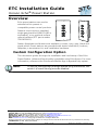
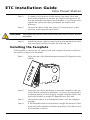
Overview
Echo preset stations are used to
activate built-in presets in
compatible power control products.
Stations mount using a standard
single-gang back box (RACO 690 or
equivalent), or an optional surface
mount backbox (ETC part number
7081A2004-1).
Station faceplates and buttons are available in cream, ivory, grey, black and
signal white. Preset stations are provided with station electronics, buttons,
faceplate, a termination kit, and installation hardware.
Custom Configuration Option
This document guides through the installation and local setup of the Echo
Preset Station. Advanced functionality is available using EchoAccess. For more
information, reference the EchoAccess Mobile App integrated help system.
Note:
To use the configuration settings applied using EchoAccess, DIP
switch 2 (Custom Config) must be enabled.

ETC Installation Guide
Echo Preset Station
Echo Preset Station Page 2 of 8 Electronic Theatre Controls, Inc.
Prepare for Installation
Preset stations connect to the EchoConnect station communication bus.
EchoConnect is a bidirectional protocol that uses one pair of wires (data+ and
data-) for both data and power. ETC recommends using Belden 8471 (or
approved equal) Class II wire. The total combined length of an EchoConnect
wire run (using Belden 8471, or equal) may not exceed 1,640 feet (500m).
Environmental
For indoor installation only - 0-50°C, 5-95% non-condensing humidity.
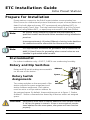
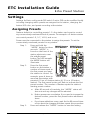
Rotary and Dip Switches
Rotary and DIP switch settings are accessible
on the rear of the station.
Rotary Switch
Assignments
Two rotary switches on the rear panel of the
station provide for space assignment and
station address assignment. Each station
must be set to a unique station address for
the assigned space. By default, these switches are set to Space 1, Station
Address 1. Station commands are shared by all devices within an assigned
space.
Note:
All control wiring should be installed and terminated by a
qualified installer and should follow standard wiring installation
practices.
Leave approximately 10 inches (254mm) of wiring in the back box
for connection and to allow slack for future service needs.
Note:
ETC requires that all stations be grounded. Pull an additional 14
AWG (1.5mm2) wire for grounding when control wires are not
installed in grounded metal conduit.
CAUTION:
Each station must have its station address set to a unique number
(1-16) for the space it controls. If two or more stations use the
same address for the same space, the system will not function
properly.
Address
Space
DIP
switches

ETC Installation Guide
Echo Preset Station
Echo Preset Station Page 3 of 8 Electronic Theatre Controls, Inc.
DIP Switch Settings
Functionality is set using DIP switches located just beneath the rotary and DIP
switches. The label on the rear of the station identifies these components and
functions.
Installation
Installation should follow all local codes and standard electrical practices.
The back box should be installed plum and square for best results. Ensure that
the back box is clean and free of obstructions and that all wiring is installed
correctly.
Echo Preset Stations ship with a termination kit for use with Belden 8471 (or
equivalent wire) and contains a power pigtail a ground wire pigtail, spacers,
and all required wire termination connectors for installation.
Switch # Use
1
Use Off - When this is set to Off, the “Off” function of the station
is not provided.
2
Custom Config - Must be set to On to use configuration settings
applied using EchoAccess. The default position is Off.
3
Disable IR Input - When On, the infrared input for this station will
be disabled.
4
Fade Time Disable - Applies a 0 second fade time to all station
actions for non-dim switched mode behavior (when dimming
features are not wanted).
5 Future development
6 Future development
7 Future development
8
Restore to Defaults at Boot - Setting this DIP switch On, then
cycling power to the station restores the station to factory defaults.
Reset the switch Off after power cycle.
Note:
NEC Class 2 product to be wired in accordance with NEC Article
725 and local jurisdiction requirements.

ETC Installation Guide
Echo Preset Station Page 4 of 8 Electronic Theatre Controls, Inc.
Connect the Wiring
Step 1: Pull all required wiring (data+,
data -) into the back box. As
needed, pull an additional ESD
ground wire (required only
when the station is not
installed in grounded metal
conduit).
Step 2: Connect station ESD ground
wire pigtail.
a: Strip 3/8” (9-10mm) of insulation from the ends of the
station ground wire pigtail, provided in the termination
kit, and the incoming ground wire.
b: Use one WAGO connector, provided in the termination
kit, to connect the station ESD ground pigtail and the
incoming ground. For stations using grounded metal
conduit, connect the ground pigtail to the metal backbox
ground location.
c: Install the ESD ground wire pigtail Faston connector to
the spade terminal on the station electronics.
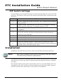
Step 3: Terminate and connect EchoConnect wires. EchoConnect is
topology free, you may install the wires in any combination of
bus, star, loop, or home-run.
a: Strip 3/8” (9-10mm) from the ends of each power pigtail
wire, provided in the termination kit, and the installed
control wires.
b: Use one WAGO connector, provided in the termination
kit, to connect the power pigtail and the installed control
wires. Open the terminal levers on the WAGO connector
and insert the installed (typically black) Belden 8471 wire
Note:
A ground connection (14 AWG) is required for any station not
installed with grounded metal conduit.
Ground
spade
Data
connector

ETC Installation Guide
Echo Preset Station
Echo Preset Station Page 5 of 8 Electronic Theatre Controls, Inc.
and the black lead from the power pigtail into the
terminals. Then close the levers.
c: Repeat for the installed (typically white) Belden 8471
power wires and the remaining white wire from the
power pigtail using a new WAGO connector.
d: Install the two pin connector from the power pigtail to
the mating receptacle on the station electronics.
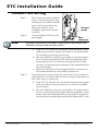
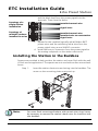
Installing the Station in the Backbox
Spacers are provided to help position the station and cover flush with the wall
in flush mount applications. The spacers are not used with surface mount back
boxes.
Step 1: Insert the station electronics and wiring into the backbox. The
arrow on the mounting plate must point up.
Note:
For some flush mount applications with certain trim rings it may
be necessary to remove the station’s back cover for insertion into
the backbox.
Topology of a
single station
installation
Topology of
multiple stations
installed in series
Installed control wire
Pigtail wire
Installed control wire
Installed wire to next station
Pigtail wire
1
3
2
4

ETC Installation Guide
Echo Preset Station
Echo Preset Station Page 6 of 8 Electronic Theatre Controls, Inc.
Step 2: If needed, fold sections of the spacer over each other and
press them together to achieve the required thickness to fill
the gap between the station and backbox. Cut off any excess
spacers and place the spacer between the station and
backbox.
Step 3: Secure the station with two screws. If using spacers, make
sure the screws pass through them.
Step 4: Install the button caps (included with the faceplate kit) so that
the clear light tunnels protrude through the caps.
Installing the Faceplate
The faceplate is secured to the station with two magnets that are located on
the bottom edge of the faceplate.
Step 1: Align the top of the faceplate approximately 20 degrees to the
station.
Step 2: Hook the top of the faceplate on the tabs located on the top
of the station electronics assembly. To ensure the faceplate is
hooked properly on the top hook, wiggle it slightly side to side
while the bottom is angled 20 degrees from the wall.
Step 3: Swing the bottom of the faceplate down until the magnets
engage.
Step 4: If the faceplate does not fully attach, wiggle the bottom of the
plate until the magnets are seated properly to the station and
the faceplate is secure.
CAUTION:
Overtightening of the mounting screws may result in poor button
activation.

ETC Installation Guide
Echo Preset Station
Echo Preset Station Page 7 of 8 Electronic Theatre Controls, Inc.
Settings
Settings for Basic config mode (DIP switch 2 set to Off) can be modified locally
including changing which presets are assigned to the station, changing the
button LED color, and preset recording at the station.
Assigning Presets
Stations default to controlling presets 1-5. Any station can be set to control
any consecutively numbered block of presets. For example: a 5-button station
can control presets 1-5, 3-7, 14-18, and so on.
Power must be connected to the station to assign the presets. To set the
consecutively numbered presets for any station:
Step 1: Press and hold the
“MODE” button for three
seconds. “MODE” is
found on the front of the
station electronics near
the middle preset
button.The LED beneath
the MODE button will
illuminate.
Step 2: Press the first preset
button on the station a
number of times equal to
the first preset you want
the station to control. For
example: press 6 times to
associate the station with
presets 6-10 on a 5-button station (6-15 on a 10-button
station). The first preset button will flash to indicate the first
preset number. The number of flashes equals the station’s
starting preset number.
a: After 90 seconds of inactivity, the “MODE” status will
time out and any changes will be aborted.
b: Button presses are cumulative. If you need to increase the
desired number, press the first preset button additional
times.
c: If you have added too many, wait for the 90 second time-
out to abort the changes and then repeat this procedure.
Step 3: Press and release the “MODE” button to save the setting.
MODE Button
on 5-button
MODE Button
on 10-button

ETC Installation Guide
Echo Preset Station
Echo Preset Station Page 8 of 8 Electronic Theatre Controls, Inc.
Changing Button LED Color
Stations default to illuminating preset buttons in green. To change the color of
the LEDs for any station:
Step 1: Press and hold the “MODE” button for five seconds. “MODE”
is found on the front of the station electronics near the middle
preset button.The LED beneath the MODE button will
illuminate and all of the preset buttons will display in their
current color.
Step 2: Press the first preset button to cycle through the available
colors until you find the desired one. After 90 seconds of
inactivity, the “MODE” status will time out and any changes
will be aborted.
Step 3: Press and release the “Mode” button. The selected color of
the preset buttons for that station will display.
Preset Record
To record a preset to a button on the Echo Preset Station:
Step 1: Set the desired lighting look in the space.
Step 2: Press and hold the preset button for three seconds. The preset
is recorded to the selected button. The button LED flashes four
times to confirm the record action.
Service
If you have any difficulties installing your system or with system startup please
contact ETC Technical Services at the office nearest you. ETC contact
information is located at the bottom of page 1.
-
 1
1
-
 2
2
-
 3
3
-
 4
4
-
 5
5
-
 6
6
-
 7
7
-
 8
8


Ask a question and I''ll find the answer in the document
Finding information in a document is now easier with AI
Related papers
-
ETC Echo Control Series Installation guide
-
ETC Unison Echo Installation guide
-
-
-
-
ETC 73050 Installation guide
-
-
-
-
Other documents
-
 Fire Alarm Max BG-10WP Outdoor Pull Station User manual
-
echoflex 8186M2130 Installation guide
-
EDWARDS MPSR Pull Station Installation guide
-
Leviton LEDFS-30W User manual
-
Aiphone IX-DVF-P Install Manual
-
Savant PWM-PENC3-00 Deployment Guide
-
Kenwood KDC-BT40U User manual
-
Aiphone IS-IPDVF-RP10 Operating instructions
-
 Acuity FRESCO Quick start guide
-

