Page is loading ...

AMPCS60
PREMIUM CEILING SPEAKER
INSTALLATION AND OPERATION MANUAL
SYDNEY
(NSW & ACT SALES)
149 Beaconsfield
Street Silverwater
NSW 2128
Private Bag 149
Silverwater NSW 1811
Phone: (02) 9647 1411
Fax: (02) 9648 3698
Email:
MELBOURNE
(VIC & TAS SALES)
22/277
Middleborough Road
Box Hill VIC 3128
PO Box 151 Blackburn
South VIC 3130
Phone: (03) 9890 7477
Fax: (03) 9890 7977
Email:
BRISBANE
(QLD SALES)
42 Commercial Road
Fortitude Valley
QLD 4006
PO Box 871 Fortitude
Valley QLD 4006
Phone: (07) 3852 1312
Fax: (07) 3252 1237
Email:
ADELAIDE
(SA & NT SALES)
31 Walsh Street
Thebarton
SA 5031
PO Box 157
Hindmarsh SA 5007
Phone: (08) 8352 4444
Fax: (08) 8352 4488
Email:
PERTH
(WA SALES)
299 Fitzgerald Street
West Perth WA 6005
PO Box 404
North Perth
WA 6906
Phone: (08) 9228 4222
Fax: (08) 9228 4233
Email:
AUCKLAND
(NZ SALES)
Unit B, 11 Piermark
Drive Albany 1331
New Zealand
PO Box 512
Albany 1331
Phone: (09) 415 9426
Fax: (09) 415 9864
Email:
AUSTRALIA AND NEW ZEALAND
www.australianmonitor.com.au
INTERNATIONAL SALES
149 Beaconsfield Street Silverwater NSW 2128 Australia
Private Bag 149 Silverwater NSW 1811
Phone: 61 2 9647 1411
Fax: 61 2 9648 3698
Email: international@audiotelex.com.au
EUROPE/ASIA/MIDDLE EAST
www.australianmonitor.com.au

1. Save the carton and packing material even if the equipment has
arrived in good condition. Should you ever need to ship the unit,
use only the original factory packing.
2. Read all documentation before operating your equipment.
Retain all documentation for future reference.
3. Follow all instructions printed on unit chassis for proper operation.
4. Do not spill water or other liquids into or on the unit, or operate the
unit while standing in liquid.
5. Make sure power outlets conform to the power requirements listed
on the back of the unit.
6. Do not use the unit if the electrical power cord is frayed or broken.
The power supply cords should be routed so that they are not likely
to be walked on or pinched by items placed upon or against them,
paying particular attention to cords and plugs, convenience
receptacles, and the point where they exit from the appliance.
7. Always operate the unit with the AC ground wire connected to the
electrical system ground. Precautions should be taken so that the
means of grounding of a piece of equipment is not defeated.
8. Mains voltage must be correct and the same as that printed on the
rear of the unit. Damage caused by connection to improper AC
voltage is not covered by any warranty.
9. Have gain controls on amplifiers turned down during power-up to
prevent speaker damage if there are high signal levels at the
inputs.
10. Power down & disconnect units from mains voltage before making
connections.
11. Never hold a power switch in the “ON” position if it won’t stay
there itself!
12. Do not use the unit near stoves, heat registers, radiators, or other
heat producing devices
13. Do not block fan intake or exhaust ports. Do not operate
equipment on a surface or in an environment which may impede
the normal flow of air around the unit, such as a bed, rug,
weathersheet, carpet, or completely enclosed rack. If the unit
is used in an extremely dusty or smoky environment, the unit
should be periodically “blown free” of foreign matter.
14. Do not remove the cover. Removing the cover will expose you to
potentially dangerous voltages. There are no user serviceable
parts inside.
15. Do not drive the inputs with a signal level greater than that
required to drive equipment to full output.
16. Do not connect the inputs / outputs of amplifiers or consoles to
any other voltage source, such as a battery, mains source, or
power supply, regardless of whether the amplifier or console is
turned on or off.
17. Do not run the output of any amplifier channel back into another
channel’s input. Do not parallel- or series-connect an amplifier
output with any other amplifier output.
Australian Monitor Inc is not responsible for damage to
loudspeakers for any reason.
18. Do not ground any red (“hot”) terminal. Never connect a “hot”
(red) output to ground or to another “hot” (red) output!
19. Non-use periods. The power cord of equipment should be unplugged
from the outlet when left unused for a long period of time.
20. Service Information Equipment should be serviced by qualified
service personnel when:
A. The power supply cord or the plug has been damaged.
B. Objects have fallen, or liquid has been spilled into the
equipment
C. The equipment has been exposed to rain
D. The equipment does not appear to operate normally,
or exhibits a marked change in performance
E. The equipment has been dropped, or the enclosure damaged.
INTRODUCTION AND CONTENTS
Thank you for choosing the Australian
Monitor AMPCS60 premium ceiling
speaker.
The AMPCS60 has been developed using
innovative design and materials to meet
the demanding constraints of high quality
foreground/background sound
reproduction from a ceiling-mounted
speaker. Featuring a sealed metal back box,
the 6.5" woofer gives superior bass
response to a conventional ceiling speaker.
The 3/4" titanium tweeter is horn-loaded
to maximize high-frequency coverage.
Rated at 60 watts, with 70/100V tappings
at 7.5, 15, 30 and 60 watts, the AMPCS60
also features a 16 ohm transformer bypass
setting.
Included mounting hardware give ease of
installation combined with safety.
FEATURES 2
INSTALLATION 3
SPECIFICATIONS 8
This symbol is intended to alert the user to the presence
of uninsulated “dangerous voltage” within the product’s
enclosure that may be of sufficient magnitude to
constitute a risk of electric shock to persons.
This symbol is intended to alert the user to the presence
of important operation and maintenance (servicing)
instructions in the literature accompanying the appliance.
To prevent electric shock do not use this (polarised) plug
with an extension cord, receptacle or other outlet unless
the blades can be fully inserted to prevent blade exposure.
To prevent electric shock, match wide blade of plug to
wide slot, fully insert.
Caution:
AUS, EUR, USA
Copyright 7 Nov 2005
Rev A: 7 Nov 2005
IMPORTANT SAFETY INFORMATION
THIS SAFETY INFORMATION IS OF A GENERAL NATURE AND MAY BE SUPERSEDED BY INSTRUCTIONS CONTAINED WITHIN THIS MANUAL

INSTALLATION
The AMPCS60 and supplied mounting hardware has been designed for easy installation
while maintaining a high standard of safety. The whole installation process can be completed
from below the ceiling, if necessary, although working from both sides of a ceiling tile is faster.
To ensure a reliable installation, please follow these steps carefully.
1. Preparation
Determine the correct mounting hardware for your particular ceiling construction
(see diagram 2).
The C-Bracket spreads the clamping force of the mounting tabs, and strengthens the edge
of the hole. The C-Bracket may be used without the tile rails.
The Tile Rails spread the weight of the speaker across the ceiling. If the ceiling tile should
fall out or break, the Tile Rails will catch onto the ceiling grid and prevent the speaker
from falling.
NOTE: Due to the wide response of the AMPCS60, the low frequency vibrations generated
may cause buzzing or rattling in some ceilings. Damping material under the Tile
Rails or the edges of the ceiling tiles may be required.
2. Cut hole
Determine the speaker position, taking into account any obstructions in the ceiling space.
Note that clearance of 185mm above the lower face of the ceiling is required.
Cutout diameter is 223mm. The C-Bracket can be used as a template.
AMPCS60 INSTALLATION & OPERATION MANUAL
PAGE 3
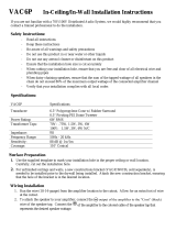
FEATURES
Tap Selector
Loudspeaker Driver
Attachment Screws
Steel Backcan
Secondary Support Tab
Rotating
Mounting
Tabs
Removable
Input
Connector
Perforated
Press-In Grille
Diagram 1
AMPCS60 INSTALLATION & OPERATION MANUAL
PAGE 2

INSTALLATION
4. Wiring
Remove the supplied 4-pole connector from the speaker, and terminate to speaker cable
(see diagram 3).
Loop-through terminals are provided (see diagram 4). When this wiring method is
used, you should be aware that when a speaker is not plugged in there is no path to
subsequent speakers.
An alternative is to wire incoming and outgoing cables in parallel. Pin 2 is +'ve and pin 3 is -'ve.
Diagram 4
1
2
3
4
1
2
3
4
1
2
3
4
+
-
+
-
To Subsequent
Speaker
Speaker 1 Speaker 2 Speaker 3
Power Amplifier
AMPCS60 INSTALLATION & OPERATION MANUAL
PAGE 5
INSTALLATION
3. Position mounting hardware
If working from below ceiling, mounting hardware can be disassembled, passed through
the hole, and then reassembled.
Tile Rails should be positioned over the ceiling grid, C-Bracket slides engaged, and then
locating screws tightened. See diagram 2.
Diagram 2
AMPCS60 INSTALLATION & OPERATION MANUAL
PAGE 4
CAUTION: Always use all supplied mounting hardware with ceiling tiles.
Diagram 3

INSTALLATION
AMPCS60 INSTALLATION & OPERATION MANUAL
PAGE 6
INSTALLATION
Diagram 5 Diagram 6
1
0
0
v
7
0
v
1
5
3
0
6
0
6
0
3
0
1
5
7
.
5
P.S
P.S
Diagram 7
AMPCS60 INSTALLATION & OPERATION MANUAL
PAGE 7
6. Select power
Using a flat-bladed screwdriver, rotate the Tap Selector
so the correct power setting is adjacent to the arrow. Note
that there are separate 70V and 100V scales, depending
on the amplifier being used (see diagram 7).
The transformer may also be by
passed by selecting the PS position.
It may be desirable to leave the grilles
off until commissioning is completed
if adjustments are likely to be needed.
7. Fit grille
Carefully insert the perforated grille into the speaker body and press in firmly.
To prevent the grille from vibrating loose, ensure that it is fully pressed in.
5. Install speaker
Insert pre-wired connector, ensuring correct polarity.
Attach secondary support to the tab, if required by local building regulations.
Lift speaker into hole and tighten the 4 mounting tabs using a screwdriver (see diagram 5,6).
Do not over-tighten.
CAUTION: To avoid distortion or equipment damage, carefully consider the
power ratings of both amplifiers and speakers.
Only 2 speakers at 60W will fully load a 120W amplifier, but note that each
will be producing more than 106dB direct Sound Pressure Level at the listener
when installed in a 3m ceiling! Dropping to the 15W tap allows 8 speakers
to be driven by the same amplifier, each producing 100dB SPL.
If 60W @ 70V is selected, but 100V line amplifier is connected, the speaker
will draw up to 120W and damage is likely.

SPECIFICATIONS
Model AMPCS60
Low-frequency driver 160mm diameter woofer
High-frequency driver 19mm diameter horn loaded tweeter
Power tappings/Impedance W (100V) W (70V) ohms
-6084
60 30 167
30 15 333
15 7.5 667
bypass 16
Frequency response 100Hz - 20kHz
Driver power 30Wrms 60Wpeak
Sensitivity 92dB (1W/1m)
Weight 3.3kg
Cutout hole diameter 223mm
AMPCS60 INSTALLATION & OPERATION MANUAL
PAGE 8
/