Page is loading ...

Info
Link
PVS5120
Portable
Water Samplers
RS-485 Options
• When sampling hydrocarbons, grease, oil, etc., regular cleaning of the meter-
ing chamber, volume control tube, liquid detect/conductivity rod, and intake
ow tubing is essential to continuous successful sampling.
• Placing the end of the intake tubing directly on sand and gravel beds can
result in unrepresentatively high sediment loads being collected. If a strainer
is not used, gravel and sand may lodge in and plug the intake tube, metering
chamber, and sampler distribution body (discrete sampler only).
• Connecting the battery cables improperly will cause the PVS5120 fuses to
blow in order to protect the PVS5120. Replace them with the same rated
fuses as the originals. (28314-5A, 28315-10A)
• Before deploying, check all connections, intake tubing, vacuum tubing, and
the meter chamber cover for proper tightness and seating to prevent air
leakage.
• Exercise proper lifting techniques when hefting this product.
• Damages caused by freezing conditions will not be covered by the warranty.
• When the PVS5120 is being stored for periods of time, disconnect the battery
to reduce discharge over time.
Caution!
!
Required Gear
• Sampler (top, control section, base with bottles)
• 7/8” wrench (adjusting rods)
• 9/16” wrench (adjusting rods)
• 5/32” Allen wrench (adjusting rods)
• Small Flat head screw driver (wiring to PVS5120)
• USB cable (connecting to VSC100)
• Control cable (connects datalogger to sampler)
• 12V Battery
• External power cable (only if using an external battery)
• Datalogger with its own power supply, protected in an enclosure if necessary
• MD485 and cable (SC12 serial cable)
• 3/8” Hose clamp to connect intake hose to the sampler
• Laptop Computer with Device Conguration Utility (DevCong 2.09 or higher)
• 1/4” nut driver (to tighten hose clamps)
• If using an external battery, make sure the external power cable (Fig. 1D) is
stripped and the correct leads are in place to connect to the battery. Connect
the external power cable to the front of the sampler (Fig 2).
• Connect the yellow caps around the fuse.
5. Turn on the sampler and set the 3-way switch on the control panel to the power
source being used (Fig. 2). If powered correctly, the green indicator light (Fig. 2) will
come on for several seconds, and then start blinking green once per second.
6. Connect the intake hose and tighten the hose clamp.
7. Put the sinker end of the intake hose into the water body to be sampled, ensuring at
least 3 inch depth.
8. Run the Autodeploy routine by pushing and holding the manual control button until
the sampler begins running (hold the button shown in Fig. 2 and 3 for approximately
5 seconds). The Autodeploy routine will set the purge and vacuum times based on
the length of the hose and the change in height between the sampler and the water
source. Wait for the sampler to stop before proceeeding to Step 9.
9. Remove the control section of the sampler and empty the sample just collected.
10. Push the Manual Control button ONCE (Figs. 2 and 3). This will “service the
Refer to Figure 1a.
1. Loosen the brass nut to set the volume control tube to the approximate volume re-
quired for collection. Align the base of the tube with the desired graduated marking
on the metering chamber. It is best to collect this volume at least once to make sure it
matches expectations. If necessary, adjust the tube up or down to obtain the desired
collection volume.
2. Set the height of the conductivity rod. The bottom of the conductivity rod must be
higher in the metering chamber than the volume control tube (at least 1/2”), but
below the bottom of the oat valve barrier.
3. Connect the positive lead to the top of the conductivity rod (yellow cap).
4. Connect the battery.
• If using an internal battery, place it in the mount and connect the red and black
leads to the matching terminals.
QUICK DEPLOY GUIDE
PVS5120C Shown.
PN 31279 1/16
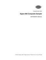
Figure 1A- PVS5120D
Introduction:
This guide provides the steps to set up and run a PVS5120 sampler using RS-485 and a Campbell Scientic datalogger in two common deployments: A) via Mod-
bus and B) via PakBus.
Figure 1B - USB Cable Figure 1C - Control Cable Figure 1D - Power Cable
Figure 2
Figure 3
1
Physical Deployment
2
Intake Hose Connection
Intake Hose
Float Valve Barrier
Top Handle
Enclosure
Sample Bottles
Retaining Plate
T-Bar
1L Base
Sinker (Optional Strainer)
Wiring
Control Panel
Nuts To Adjust Volume Control Tube
Liquid Detect / Conductivity Rod
Metering Chamber
Volume Control Tube
VSC100 Controller
Clasp
Folding Handles
500 mL Base
Bottle Notch Guide
Fuse
Battery
IMPORTANT NOTE: This Quick Deploy Guide is a general reference
guide to give the installer an overview of the steps required to make
this system operational. The Owner’s Manual is the denitive source for
detailed installation instructions and information.

sampler” and reset the sample count to 0.
11. a. Connect the USB cable (Fig. 1B) to the front of the sampler controller (VSC100)
and the other end to the laptop USB port (Fig. 4).
Wait for Windows to install the driver before
opening the software.
b. Open DevCong. Select the VSC100 Series under
the Sampler option as shown in Figure 5A. Select
the Communication Port option and nd the
correct COM port (Fig. 5B). Click Connect (Fig. 5C)
c. Click the Clock tab at the top. Next, click on Set
Clock. This will sync the sampler clock with the
computer clock.
12. It is now time to congure the rest of the sampler
settings. The sampler leaves the factory assuming
it will be controlled via SDI-12, have 24 bottles
in the base, and collect 1 sample per bottle. All of these general settings can be
easily changed. Proceed to Section 3, Conguring the MD485. Continue to Section
4, Scenario A: Modbus Control Via CR1000 or Section 5, Scenario B: Pakbus Control Via
CR1000.
1. Connect a serial cable to the RS-232 port on the MD485 and to the laptop.
2. Supply power (12 Vdc) to the MD485 by the power jack or through the +12 V line on the
CSIO connector.
3. Open Devcong. Click on peripheral (Figure 6A). Select MD485 (Figure 6B). Select com-
munication port (Figure 6C). Push the Program button on the MD485. Click Connect
(Figure 6D). The Program button is located to the right of the RS-485 connectors on
the modem’s front panel.
4. Click the MD485 tab. Select CS I/O and RS-485 in the Active Ports box (Figure 7A).
And select Transparent Communication in the Protocol box (Figure 7B).
5. Click the CS I/O tab. Set the CS I/O mode based on the datalogger used. In this exam-
ple, a CR1000 is used, so SDC Address 7 is chosen (Figure 8A).
6. Click the RS-485 tab. Set the Baud Rate to 38.4k (Figure 9A). Set the Parity to None
(Figure 9B). Set the character length to 8 bits (Figure 9C). Set the Stop Bits to 1 bit
(Figure 9D).
7. Click Apply.
1. Click the Sampler Settings tab (Figure 10).
A. Set the Control Type to Modbus
B. Set the Modbus Address. This is the address of the
sampler and will be referenced in the CRBasic program
running on the datalogger. Possible address choices are
1–127.
C. Set the Number of Sample Bottles. This can range from
1–24.
D. Set the Samples Per Bottle
E. The Never Full Operation is a special conguration and
should remain disabled for most users. See the manual
for an explanation of Never Full.
F. If the Autodeploy routine described in Section 2 has been
performed, the Purge Time will already be set.
G. Change this setting if a Water Present Sensor is to be to
installed. This sensor is wired to the sampler control
cable. See the manual for more information.
2. Click the Advanced Sampler Settings tab (Figure
11). If the Autodeploy routine has been run, many of
these settings will already be set.
A. Set Sample Chamber-Pressure Relief. If collecting
a sample volume > 450 mL or if the intake hose
is longer than 50 ft, This feature will need to be
enabled.
3. Click Apply. The option to save this conguration
to le is given. It is a good idea to always keep the
conguration le for future reference.
Modbus Coil Map
Modbus Coils Coil # Start
Start 00001 1
Service 00002 2
Auto Deploy 00003 3
1. Click the Sampler Settings tab (Figure 12).
A. Set the Control Type to Pakbus.
B. Set the Pakbus Address. This is the address of the sampler
and will be referenced in the CRBasic program running on
the datalogger.
C. Set the Number of Sample Bottles. This can range from
1–24.
D. Set the Samples per bottle
E. The Never Full Operation is a special conguration and
should remain disabled for most users. See the manual
for an explanation of Never Full.
F. If the Autodeploy routine described in Section 2 has been
performed, the Purge Time will already be set.
G. Change this setting if a Water Present Sensor is to be in-
stalled. This sensor is wired to the sampler control cable.
See the manual for more information.
2. Click the Advanced Sampler Settings tab (FIgure 11). If the Autodeploy routine has
been run, many of these settings will already be set.
A. Set Sample Chamber-Pressure Relief. If collecting a sample volume > 450 mL, or if
the intake hose is longer than 50 ft, this feature will need to be enabled.
3. Click Apply. The option to save this conguration is given. It is a good idea to always
keep the conguration le for future reference.
Wiring of the sampler cable to the datalogger and program values are the same for
Modbus and PakBus and are listed below. The only dierence will be the commands used
in the CRBasic program.
1. Connect the Control Cable (Fig. 1C) to the front of the PVS5120 (Fig. 2). Next, wire the
cable to the MD485.
Wire color Port on MD485
White RS-485 A-
Black RS-485 B+
Brown Resistive Ground
2. Example CRBasic programs available on the website show how to control a PVS5120 via
RS-485 with a CR1000. Other programs are available at the Campbell Scientic website.
There are multiple best practices for programming the Sampler. Refer to the manual for
this information. www.campbellsci.com/pvs5120d.
3. Connect to the datalogger. The following steps assume a knowledge of how to set up a
CR1000 and connect via a direct connection or remote connection. See the datalogger
manual for more detailed instructions on connecting to the datalogger.
A. From the LoggerNet Connect screen click on Collect Now to collect any data on the
datalogger.
B. From the Connect screen, click on the Send button. Browse to nd the CRBasic
program that controls the PVS5120 via either Modbus or PakBus. Click Open, and
then click Send.
C. Below is the register map or array values for the VSC100. These values will not
translate to Modbus/PakBus monitoring of a PVS5120 when it is being controlled via
Pulse or Time. See the manual for more information. Also these array values are not
aliased in the VSC100.
Modbus Register Map and PakBus Public Table
Reg Array
Start Value Name Description
1 1 Bottles Number of bottles in sampler.
3 2 SampPerBottle Number of samples to be put in each bottle(s)
5 3 NeverFull Determines if the sampler loops without stopping (Requires Human Service before
Sampler is full to prevent overow).
7 4 PurgeTime1 Purge Time 1 (Initial Purge Time) time in seconds the sampler hose is purged before
collecting sample.
9 5 LevelSetTime Time in seconds to evacuate sample chamber to desired sample volume.
11 6 DepositTime Time in seconds to hold Pinch Valve open to allow sample to be deposited in bottle.
13 7 PurgeTime2 Final purge time in seconds the sampler hose is evacuated after collecting sample.
15 8 UsePurgeTime2 A True/False variable which indicates if PurgeTime2 is set independently of
PurgeTime1 or is set to same value as PurgeTime1.
17 9 SetTimeOut True/False value to determing if the vacuum time will be 2xPurgeT1 or set
independently.
19 10 TimeOut Vacuum timeout in seconds to determine how long sampler should attempt to
collect a sample before triggering an error.
21 11 SamplerType The sampler type determined by the corresponding integer value: 0 = Pakbus, 1 =
Pulse, 2 = Modbus, 3 = SDI-12
23 12 Bottle Indicates in which bottle the last sample was deposited. Always one for Composite
sampler.
1
25 13 SampleCount Displays the number of samples deposited in to bottle. Always one for Never Full
option.
1
27 14 Response Displays any Response codes. 0 indicates no errors.
1
29 15 Batt Sampler battery voltage.
1
1
These values are READ ONLY status values returned from the sampler.
Numeric response code Denition
0 No error
1 All samples complete
2 Low start battery (V < 11.0 Vdc)
3 Low run battery (V < 10.5Vdc occurs after pumping has started)
4 Sampler vacuum timed out, no sample detected
5 Sample overow detected (only if an overow sensor is installed for stationary
samplers)
6 No sample liquid detected (only if water detect sensor is installed)
7 Arm Calibration error
8 Conductivity rod and Sample tube are shorted
Conguring the MD485
Scenario A: Modbus Control Via CR1000
Figure 5
Figure 4
Scenario B: PakBus Control Via CR1000
Connecting Sensors
Interacting with the CR1000
Figure 6
Figure 7
Figure 8
Figure 9
Figure 10
Figure 11
Figure 12
3
4
5
6
A
B
C
D
A
B
C
A
B
A
A
B
C
D
A
B
C
E
D
F
G
A
/