Page is loading ...

MIT-II/E - MIT-II/H
MIT/EP - MIT/HP
QUADROPAC DUP 500
Control panel
User Guide
300015090-001-L
EN

2
MIT-II - MIT/P - QUADROPAC DUP 500 14/04/2010 - 300015090-001-L
Contents
1 Used symbols . . . . . . . . . . . . . . . . . . . . . . . . . . . . . . . . . . . . . . . . . . . . . . . . . . . . . . . . . . . . . . . . . . . . . . . . . . .3
2 Important recommendations . . . . . . . . . . . . . . . . . . . . . . . . . . . . . . . . . . . . . . . . . . . . . . . . . . . . . . . . . . . . . . .3
3 Control panel . . . . . . . . . . . . . . . . . . . . . . . . . . . . . . . . . . . . . . . . . . . . . . . . . . . . . . . . . . . . . . . . . . . . . . . . . . . .4
3.1 Electromechanical components . . . . . . . . . . . . . . . . . . . . . . . . . . . . . . . . . . . . . . . . . . . . . . . . . . . . . . . . . . . . . . . . . . . . . . . . . . . . .4
3.2 Display . . . . . . . . . . . . . . . . . . . . . . . . . . . . . . . . . . . . . . . . . . . . . . . . . . . . . . . . . . . . . . . . . . . . . . . . . . . . . . . . . . . . . . . . . . . . . . . .5
3.3 Keys accessible when the flap is closed . . . . . . . . . . . . . . . . . . . . . . . . . . . . . . . . . . . . . . . . . . . . . . . . . . . . . . . . . . . . . . . . . . . . . .6
3.4 Keys accessible when the flap is open. . . . . . . . . . . . . . . . . . . . . . . . . . . . . . . . . . . . . . . . . . . . . . . . . . . . . . . . . . . . . . . . . . . . . . . .6
3.5 Operating mode . . . . . . . . . . . . . . . . . . . . . . . . . . . . . . . . . . . . . . . . . . . . . . . . . . . . . . . . . . . . . . . . . . . . . . . . . . . . . . . . . . . . . . . . .7
4 Heating and domestic hot water temperature setting . . . . . . . . . . . . . . . . . . . . . . . . . . . . . . . . . . . . . . . . . . .9
4.1 Heating temperature setting . . . . . . . . . . . . . . . . . . . . . . . . . . . . . . . . . . . . . . . . . . . . . . . . . . . . . . . . . . . . . . . . . . . . . . . . . . . . . . . .9
4.2 DHW set temperature. . . . . . . . . . . . . . . . . . . . . . . . . . . . . . . . . . . . . . . . . . . . . . . . . . . . . . . . . . . . . . . . . . . . . . . . . . . . . . . . . . . . .9
5 Programming . . . . . . . . . . . . . . . . . . . . . . . . . . . . . . . . . . . . . . . . . . . . . . . . . . . . . . . . . . . . . . . . . . . . . . . . . . .10
5.1 Selecting a programme . . . . . . . . . . . . . . . . . . . . . . . . . . . . . . . . . . . . . . . . . . . . . . . . . . . . . . . . . . . . . . . . . . . . . . . . . . . . . . . . . .10
5.2 Hot water programme. . . . . . . . . . . . . . . . . . . . . . . . . . . . . . . . . . . . . . . . . . . . . . . . . . . . . . . . . . . . . . . . . . . . . . . . . . . . . . . . . . . .10
5.3 Auxiliary programme. . . . . . . . . . . . . . . . . . . . . . . . . . . . . . . . . . . . . . . . . . . . . . . . . . . . . . . . . . . . . . . . . . . . . . . . . . . . . . . . . . . . .10
5.4 Customising the programmes. . . . . . . . . . . . . . . . . . . . . . . . . . . . . . . . . . . . . . . . . . . . . . . . . . . . . . . . . . . . . . . . . . . . . . . . . . . . . .10
5.5 Resetting the programmes . . . . . . . . . . . . . . . . . . . . . . . . . . . . . . . . . . . . . . . . . . . . . . . . . . . . . . . . . . . . . . . . . . . . . . . . . . . . . . . .10
6 "User" settings . . . . . . . . . . . . . . . . . . . . . . . . . . . . . . . . . . . . . . . . . . . . . . . . . . . . . . . . . . . . . . . . . . . . . . . . .11
6.1 Table of "User" setting . . . . . . . . . . . . . . . . . . . . . . . . . . . . . . . . . . . . . . . . . . . . . . . . . . . . . . . . . . . . . . . . . . . . . . . . . . . . . . . . . . .12
6.2 Customising the programmes. . . . . . . . . . . . . . . . . . . . . . . . . . . . . . . . . . . . . . . . . . . . . . . . . . . . . . . . . . . . . . . . . . . . . . . . . . . . . .15
6.3 Miscellaneous settings . . . . . . . . . . . . . . . . . . . . . . . . . . . . . . . . . . . . . . . . . . . . . . . . . . . . . . . . . . . . . . . . . . . . . . . . . . . . . . . . . . .16
6.4 Setting the time and the date - Summer time . . . . . . . . . . . . . . . . . . . . . . . . . . . . . . . . . . . . . . . . . . . . . . . . . . . . . . . . . . . . . . . . . .16
7 Message . . . . . . . . . . . . . . . . . . . . . . . . . . . . . . . . . . . . . . . . . . . . . . . . . . . . . . . . . . . . . . . . . . . . . . . . . . . . . . .16
8 Maintenance. . . . . . . . . . . . . . . . . . . . . . . . . . . . . . . . . . . . . . . . . . . . . . . . . . . . . . . . . . . . . . . . . . . . . . . . . . . .17
8.1 Maintenance contract . . . . . . . . . . . . . . . . . . . . . . . . . . . . . . . . . . . . . . . . . . . . . . . . . . . . . . . . . . . . . . . . . . . . . . . . . . . . . . . . . . . .17
8.2 Fault finding . . . . . . . . . . . . . . . . . . . . . . . . . . . . . . . . . . . . . . . . . . . . . . . . . . . . . . . . . . . . . . . . . . . . . . . . . . . . . . . . . . . . . . . . . . .17
9 Diagnosing breakdowns . . . . . . . . . . . . . . . . . . . . . . . . . . . . . . . . . . . . . . . . . . . . . . . . . . . . . . . . . . . . . . . . . .18

3
14/04/2010 - 300015090-001-L MIT-II - MIT/P - QUADROPAC DUP 500
Congratulations on choosing a De Dietrich product, a product of quality. We strongly recommend that you read the following instructions in
order to guarantee the optimal operation of your appliance. We are sure that you will not be disappointed and that it will satisfy all of your
expectations.
1 Used symbols
Caution danger
Risk of injury and damage to equipment. Attention must be
paid to the warnings on safety of persons and equipment
Specific information
Information must be kept in mind to maintain comfort
Z
Refer to another manual or other pages in this instruction
manual
DHW: Domestic hot water
MIT: Indoor module fitted with a Diematic 3 control panel
HP or PAC: Heat pump.
2 Important recommendations
For a proper operating of the boiler, follow carefully the
instructions.
Any intervention on the appliance and heating equipment
must be carried out by a qualified technician.
The manufacturer is not liable for any improper use of the
appliance or failure to maintain or install the unit correctly
(the user shall take care to ensure that the system is
installed by a qualified fitter).

4
MIT-II - MIT/P - QUADROPAC DUP 500 14/04/2010 - 300015090-001-L
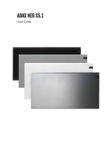
3 Control panel
3.1 Electromechanical components
1. Main ON/OFF switch
To take advantage of the pump cleaning function, do not switch
off the appliance in summer. Use the Summer mode for the
desired heating shutdown period.
Z
See: Operating mode.
If a remote control CDI 2 is connected, it will have no display
when the general switch is in the off position
.
2. Pressure gauge
* Depending on the model of the appliance, the pressure gauge
is manual (dial display) or automatic (pictogram display).
3. Alarm indicator
- Red indicator: The PAC is safe
- Green indicator: normal operation
- Red control light is flashing: Sensor fault
4. Reset button
2
13
0
bar
4
2*1
0 2 4 6 8 1012141618202224
A
2*
4
3
bar
C000142_00
SUNDAY
-04

5
14/04/2010 - 300015090-001-L MIT-II - MIT/P - QUADROPAC DUP 500
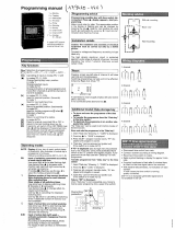
3.2 Display
0 2 4 6 8 1012141618202224
A
bar
3 4 5 6 7
91011
8
2
1
BC
SUNDAY
1 Text and numerical display
2 Graphic bar displaying the programme on circuit A or B (in
zone 9)
3 Light area: Nighttime period
4 Dark area: Daytime period
5 Flashing cursor showing the current time
6 Number display (current time, adjusted values, parameters,
etc.)
7 Active programme display, P1, P2, P3, P4
or
E: Summer mode activated - heating OFF
8 Flashing arrows when the
or
keys should be used to
adjust the displayed parameter
9 Circuit operation symbols
>
Opening the 3-way valve
=
Closing the 3-way valve
:
Displayed circuit pump on
A, B Name of the circuit displayed
10 Symbol displayed above the active operating mode
11 Symbols indicating that the following inputs/outputs are
active
ROE-II - ROE+ - SOLO - NAPO - ROI+ - ROE-H
D
PAC is operating in Hot or Cold mode
X
PAC is operating in Hot mode with additional electrical heating
at stage 1
Y
PAC is operating in Hot mode with additional electrical heating
at stage 2
Additional electrical heating operating, stage 1. PAC off
Additional electrical heating operating, stage 2. PAC off
DHW production pending with the thermodynamic unit
#
Forced "summer" condition
ROE+ TH
D
PAC is operating in Hot mode with 1 compressor
E
PAC is operating in Hot mode with 2 compressor
X
PAC is operating in Hot mode with 2 compressors and 1 back-
up provision
Y
PAC is operating in Hot mode with 2 compressors and 2 back-
up provision
Additional electrical heating operating, stage 1. PAC off
Additional electrical heating operating, stage 2. PAC off
DHW production pending with the thermodynamic unit
#
Forced "summer" condition
Water pressure display, user interface
Insufficient pressure: add water (0 - 0.5 bar)
U
Addition of water recommended (0.5 - 1 bar)
T
Pressure correct (1 - 2 bar)
Too much pressure (> 2 bar)

6
MIT-II - MIT/P - QUADROPAC DUP 500 14/04/2010 - 300015090-001-L
3.3 Keys accessible when the flap is closed
3.4 Keys accessible when the flap is open
024681012141618202224
A
C000142_02
SUNDAY
-04
Temperature setting keys
2%
Daytime temperature
2$
Nighttime temperature
2
Domestic hot water temperature
/
Is used to adjust the selected temperature
When one of these keys is pressed, the active time
programme corresponding to the circuit is displayed in the
graphic bar
Operating mode selection keys
AUTO
Heating according to the time programme
%
Forced operation at Daytime temperature
$
Forced operation at Nighttime temperature
.
Antifreeze mode
Tank load enabled mode
A
024681012141618202224
A
STANDARD
C000142_03
SUNDAY
-04
#
Manual "Summer" shutdown key
STANDARD
"Standard" programme key
Reset of all time programmes.
K
Fitter settings access key
Key for access to setting and measurements
J
Page scrolling
I
Line scrolling
H
Return to the previous line
Programming keys
%O
Input (per 1/2 hour) of the Daytime Temperature period
$P
Input (per 1/2 hour) of the Nighttime Temperature period
S
Return key
A.B
Circuit display selection key
PROG
Active heating programme selection key (P1, P2, P3 or
P4)

7
14/04/2010 - 300015090-001-L MIT-II - MIT/P - QUADROPAC DUP 500
3.5 Operating mode
Select the operating modes using the AUTO -
%
-
$
-
.
keys.
These keys simultaneously control all circuits connected.
To modify the operating mode (AUTO, Daytime
%
or Nighttime
$
)
for only one of the heating circuits, use the remote control
corresponding to this circuit.
An override applied to the remote control takes priority over the
override selected on the central regulator.
` AUTO key = Automatic mode
Heating according to the time programme.
Z
See: Programming.
` Key
%
= Daytime mode
The heating operates according to the Daytime temperature,
independently of the timed programmes.
` Key
$
= Night mode
The heating operates according to the Nighttime temperature,
independently of the timed programmes.
` Key
= Tank load enabled mode
Domestic hot water production is enabled, independently of the time
programme.
` Key
.
= Antifreeze mode
The heating is off but the installation is monitored and protected
against frost.
The antifreeze mode protects:
- The installation if the outside temperature is lower than 3°C
(factory setting).
- The room temperature if a remote control is connected and the
room temperature is lower than 6 °C (factory setting).
Antifreeze protection is guaranteed for each heating circuit,
regardless of the setting on the corresponding room
temperature sensor. The room temperature in "antifreeze"
mode is preset to +6 °C. This value can be modified if a room
sensor is fitted.
Z
See: Table of "User" setting.
` Key
#
(Located under the flap) = SUMMER mode / Cooling
Key
#
is used to cut off the heating and, if the corresponding
function is activated, to switch to Cooling mode.
Z
See menu #HEAT PUMP, parameter REFR.:
This function is independent of the "automatic heating shutdown"
function in summer when the outside temperature exceeds the
outside temperature for "heating shutdown".
When the heating is off during the "summer" mode, the pumps
are started up once a week for one minute in order to prevent
fouling.
The MIT interior hydraulic module operates in COOLING mode
only:
- During the
DAY
period on timed programmes
A
and
B
,
-
and
if the outside temperature is higher than the instruction
SUM/
WIN
+
SUM/WIN BAND
(Factory setting: 22 + 4 = 26 °C).
Do not use or modify this programme when operating with
the QUADROPAC domestic hot water tank.
0 2 4 6 8 1012141618202224
A
C000142_02
SUNDAY
-04
A
024681012141618202224
A
STANDARD
C000142_03
SUNDAY
-04

8
MIT-II - MIT/P - QUADROPAC DUP 500 14/04/2010 - 300015090-001-L
Brief touch Several brief touches 1 long touch (5 seconds)
AUTO key Depending on the situation:
- Cancellation of the Daytime or
Nighttime mode
- Confirmation of the antifreeze
setting (or after 2 minutes)
_
Cancels the message SHOW REM.
CTRL which signals the presence of an
override on a remote control.
The AUTO mode is forced on all
existing heating circuits.
Key
%
/
$
Temporary activation (Until midnight)
The arrow above the key flashes.
_
Permanent activation
The arrow above the key is steady.
Key
.
Temporary activation
Set the number of days' absence
(current day = 1) using keys
and
(up to 99 days).
The arrow above the key flashes.
Cancellation: The antifreeze mode is
cancelled when the number of
antifreeze days is reset to zero or when
the set time has elapsed.
Deferred temporary activation:
- First brief touch: Set the number of
days' absence (current day = 1) using
keys
and
(up to 99 days).
- Second brief touch: Set the start
month using keys
and
.
- Third brief touch: Set the start day
using keys
and
.
The arrow above the key flashes until
the start day and then becomes steady.
Cancellation: The antifreeze mode is
cancelled when the number of
antifreeze days is reset to zero or when
the set time has elapsed
.
Permanent activation
The arrow above the key is steady.
The permanent "antifreeze"
mode can also be selected
using the TELCOM 2 remote
voice monitoring module
delivered as an option.
Key
Temporary activation (Until midnight)
The arrow above the key flashes.
Second depression: Deactivation Permanent activation
The arrow above the key is steady.
Key
#
(Located
under the flap)
__First press: Permanent activation
The heating is off.
The symbol SU appears.
Second depression: Deactivation

9
14/04/2010 - 300015090-001-L MIT-II - MIT/P - QUADROPAC DUP 500
4 Heating and domestic hot water temperature
setting
4.1 Heating temperature setting
The comfort and reduced temperatures are set separately for each
circuit:
- Select the comfort temperature or the reduced temperature for the
desired circuit by successively pressing key
2%
or
2$
.
- Set the temperature using keys
and
.
The graphic bar displays the heating programme for the
displayed circuit for the current day.
End of setting: Press the AUTO key or after 2 minutes.
* Is displayed if the following 2 conditions are satisfied:
- at least one room sensor is connected on a circuit which is
configured in underfloor heating (
FL.HE.
),
- cooling mode on.
• In summer mode, when the room temperature measured by the
sensor is higher than the set point ROOM REFR.T., the cooling
mode starts up. The cooling mode shuts down when the room
temperature measured is lower than ROOM REFR.T. -0.5°C.
• In parallel, depending on the outside temperature, automatic
cooling remains on.
4.2 DHW set temperature
- Select the domestic hot water temperature using key
2
and
set the temperature using keys
or
.
If there is no domestic hot water sensor, pressing this key has
no effect.
- End of setting: Press the AUTO key or after 2 minutes.
If DHW consumption is high, increase the domestic hot water
set temperature to 60°C.
2%
Comfort temperature - Cooling
2$
Reduced temperature
2
Domestic hot water temperature
024681012141618202224
A
C000142_02
SUNDAY
-04
Temperature
2
Factory setting Adjustment range
%
DAY TEMP. A
20 °C
5 to 30 °C
In steps of 0.5°C
ROOM REFR.T. *
25 °C
22 to 30 °C
In steps of 0.5°C
$
NIGHT TEMP. A
16 °C
5 to 30 °C
In steps of 0.5°C
Temperature Adjustment range Factory setting
Domestic hot
water
2
10 to 80 °C
In steps of 5°C
55 °C

10
MIT-II - MIT/P - QUADROPAC DUP 500 14/04/2010 - 300015090-001-L
5 Programming
5.1 Selecting a programme
The DIEMATIC 3 control unit includes 4 heating programmes:
- 1 fixed programme P1, activated in the factory.
- 3 custom programmes P2, P3, P4 to adapt to the lifestyle of the
occupants.
Allocation of a programme to a circuit:
- Select the circuit using key A.B.
- Select the programme using the PROG key.
- The programme selected is active in automatic mode.
The programme for the current day can be displayed on the
graph bar using key
2%
or
2$
.
5.2 Hot water programme
The DIEMATIC 3 control unit includes a custom domestic hot water programme.
The programme for the current day can be displayed on the
graph bar using key
.
MIT
For correct operation, we recommend activating timed programmes
DHW and AUX at night to:
- Take advantatge of off-peak tariffs.
- Avoid having non-heating periods which are too long.
- Avoid switching from cold to hot operation several times a day
when the cooling mode is activated during the daytime .
QUADROPAC
Programme 2 hours of DHW loading before a large draw-off (shower,
bath, etc.).
5.3 Auxiliary programme
The DIEMATIC 3 control unit includes a custom programme on the auxiliary outlet.
Note: When you set parameter S.AUX: to AP. DHW, timed programme DHW is copied to timed programme AUX.Programme AUX can be
customised.
5.4 Customising the programmes
Z
See: 6.2 Customising the programmes (P2, P3 or P4).
5.5 Resetting the programmes
Press the STANDARD key for 5 seconds:
- All customised programmes are replaced with their factory setting.
- Programme P1 is assigned to all heating circuits.
Programme Day Daytime period
P1 Monday - Sunday 6:00 - 22:00
P2 (Factory setting) Monday - Sunday 4:00 - 21:00
P3 (Factory setting) Monday - Friday 5:00 - 8:00, 16:00 - 22:00
Saturday - Sunday 7:00 - 23:00
P4 (Factory setting) Monday - Friday 6:00 - 8:00, 11:00 - 13:30, 16:00 - 22:00
Saturday 6:00 - 23:00
Sunday 7:00 - 23:00
Programme Day Filling enabled
Tank (Factory setting) Monday - Sunday 2:00 - 6:00
Programme Day Filling enabled
AUX (Factory setting) Monday - Sunday 6:00 - 22:00

11
14/04/2010 - 300015090-001-L MIT-II - MIT/P - QUADROPAC DUP 500
6 "User" settings
When the flap is open, the keys are used to display measurements,
programme modifications and the settings of the various parameters.
The various settings and programmes are saved even when the
power supply is cut off.
A
0 2 4 6 8 1012141618202224
A
STANDARD
C000142_03
SUNDAY
-04
Key for access to setting and measurements
J
Page scrolling
I
Line scrolling
H
Back to the title or the previous line
Programming keys
%O
Input (per 1/2 hour) of the Daytime Temperature period (Dark
area)
$P
Input (per 1/2 hour) of the Nighttime Temperature period (Light
area)
S
Return key

12
MIT-II - MIT/P - QUADROPAC DUP 500 14/04/2010 - 300015090-001-L
6.1 Table of "User" setting
The different adjustable parameters are listed in their order of
appearance.
At the end of the intervention, the data is memorised after 2 minutes
or by pressing the AUTO key.
Display
ROE-II ROE-H ROE+ ROE+TH SOLO,
NAPO
ROI+
Parameter set
Factory
setting
Adjustme
nt range
#MEASURES Allows the values below to be read
TEMP.MIT x x x x x x Water temperature in the MIT-II module or
heating zone in the Quadro
--
HP FLOW TEMP. x x x Water temperature at the PAC outlet - -
SOURCE TEMP. x Refrigerant temperature at the heat pump source
end
--
COLD TEMP. x x Temperature of the PAC cold circuit - -
EVAPORATOR T. x Refrigerant temperature at the fin tube
exchanger outlet
--
OUTLET TEMP. B* x x x x x Water temperature in circuit B (Flow sensor) - -
WATER TEMP. * x x x x x Tank water temperature - -
ROOMTEMP. A* x x x x x Room temperature A - -
ROOMTEMP. B* x x x x x Room temperature B - -
OUTSIDE TEMP. x x x x x Outside temperature measured by the MIT-II
module
--
HP RETURN TEMP x x Return temperature - -
HP FLOW TEMP. x x Flow temperature - -
FLUID EVAP.T. x x Fin tube exchanger refrigerant temperature - -
FLUID COND.T. x x Refrigerant temperature at the heat exchanger - -
HOT GAS TEMP. x Refrigerant temperature at the compressor outlet - -
HP OUTSIDE T. x x x x Outside temperature measured by the PAC - -
HP FLOW TEMP. x Water temperature at the PAC outlet - -
HP RETURN TEMP x Return temperature - -
HP AIR IN T. x Outside temperature at the heat pump - -
EVAPORATOR T. x Refrigerant temperature at the fin tube
exchanger outlet
--
HOT GAS TEMP. x Compressor outlet temperature - -
PRESSION(BAR) x x x x x x Water pressure display - -
NB IMP.COMP. x x x x Number of PAC start-ups - -
NB IMP.COMP.1 x Number of start-ups on compressor 1 - -
RUNTIME COMP. x x x x x x Number of PAC operating hours
Number of hours' operation of compressor 1
--
NB IMP.COMP.2 x Number of start-ups on compressor 2 - -
RUNTIME.COMP.2 x Number of hours' operation of compressor 2 - -
CTRL x x x x x x Information reserved for the technician (Diematic
programme version)
--
* The line or title is only displayed for the options, circuits or sensors actually connected
.

13
14/04/2010 - 300015090-001-L MIT-II - MIT/P - QUADROPAC DUP 500
#PROG. CIRC.A * x x x x x x Heating programme for circuit A if used
Z
See also:
Customising the programmes.
--
PROG EVERY DAY P2 x x x x x x Used to programme every day of the week
simultaneously.
Each day can subsequently be individually
modified.
PROG MONDAY P2
PROG TUESDAY P2
PROG WEDNESDAY
P2
PROG THURSDAY P2
PROG FRIDAY P2
PROG SATURDAY P2
PROG SUNDAY P2
xxx x xx
PROG EVERY DAY P3 x x x x x x Used to programme every day of the week
simultaneously.
Each day can subsequently be individually
modified.
PROG MONDAY P3
PROG TUESDAY P3
PROG WEDNESDAY
P3
PROG THURSDAY P3
PROG FRIDAY P3
PROG SATURDAY P3
PROG SUNDAY P3
xxx x xx
PROG EVERY DAY P4 x x x x x x Used to programme every day of the week
simultaneously.
Each day can subsequently be individually
modified.
PROG MONDAY P4
PROG TUESDAY P4
PROG WEDNESDAY
P4
PROG THURSDAY P4
PROG FRIDAY P4
PROG SATURDAY P4
PROG SUNDAY P4
xxx x xx
#PROG. CIRC.B * x x x x x x Heating programme for circuit B if used
Lines as circuit A
#PROG. AUXIL x x x x x x Auxiliary contact programming
Lines as circuit A
#PROG. DHW*
x x x x x x DHW tank programming (if the domestic hot
water sensor is connected)
Display
ROE-II ROE-H ROE+ ROE+TH SOLO,
NAPO
ROI+
Parameter set
Factory
setting
Adjustme
nt range
* The line or title is only displayed for the options, circuits or sensors actually connected.

14
MIT-II - MIT/P - QUADROPAC DUP 500 14/04/2010 - 300015090-001-L
#SETTING x x x x x x The parameters are set using keys
or
.
Z
See also: Miscellaneous settings.
--
CONTRAST DISP. x x x x x x Adjusting the display contrast - -
BACK LIGHT xxx x xxON: The lighting is permanent if the circuit is in
Daytime period
. If the circuit displayed is in a
Night period, the backlighting is ECO.
ON ON, ECO
or OFF
ECO: If the circuit displayed is in Nighttime
period, the lighting is on for 2 minutes if a key on
the keyboard is pressed.
OFF: The display is never lit
SUM/WIN x x x x x x Summer/winter setting 22 °C 15 to
30 °C -
OFF
CALIBR. OUT x x x x x x Outside sensor calibration 0.0 -5.0 to
+5.0 K
CALIBR. ROOM A * x x x x x x Calibration of the room sensor on circuit A 0.0 -5.0 to
+5.0 K
OFFSET ROOM A * x x x x x x Room offset on circuit A 0.0 -5.0 to
+5.0 K
OFFSET ROOM B * x x x x x x Room offset on circuit B 0.0 -5.0 to
+5.0 K
ANTIFR. ROOM A * x x x x x x Room temperature antifreeze activation on circuit
A
6 °C 0.5 to
20 °C
CALIBR. ROOM B * x x x x x x Calibration of the room temperature sensor on
circuit B
0.0 -5.0 to
+5.0 K
ANTIFR. ROOM B * x x x x x x Room temperature at which the antifreeze mode
is activated on circuit B
6 °C 0.5 to
20 °C
#TIME . DAY x x x x x x The parameters are set using keys
or
.
Z
See also: Setting the time and the date
- Summer time.
--
HOURS xxx x xx
MINUTE xxx x xx
DAY xxx x xx
MONTH xxx x xx
DATE xxx x xx
YEAR xxx x xx
SUM. TIME: xxx x xxAUTO: automatic switch to summer time on the
last Sunday in March and back to winter time on
the last Sunday in October.
MANU: for countries where the time change is
done on other dates or is not in use.
AUTO AUTO or
MANU
Display
ROE-II ROE-H ROE+ ROE+TH SOLO,
NAPO
ROI+
Parameter set
Factory
setting
Adjustme
nt range
* The line or title is only displayed for the options, circuits or sensors actually connected.

15
14/04/2010 - 300015090-001-L MIT-II - MIT/P - QUADROPAC DUP 500
6.2 Customising the programmes
Write the customized programmes in the tables below, then save
them as follows:
1. Open the cover to access to the setting and programme keys.
2. Press key
J
to select the paragraph (#PROG. CIRC.A -
#PROG. CIRC.B - #PROG. AUXIL - #PROG. DHW)
3. Select successive lines using key
I
.
The programming selected for line PROG EVERY DAY is
automatically copied to the other lines but can still be
individually modified for each day.
4. Use key
%O
to define the daytime periods (per 1/2 hour) (dark
areas on the graphic display).
Use key
$P
to define the Nighttime periods (per 1/2 hour)
(dark areas on the graphic display).
Use the return key
S
if you make a mistake.
5. Proceed similarly for each connected circuit, if necessary.
6. When programming is completed, press key AUTO. Otherwise,
the programme will be automatically saved after 2 minutes.
To reset to the factory settings, press the key STANDARD for
5 seconds.
#PROG. CIRC.A
#PROG. CIRC.B
#PROG. AUXIL
#PROG. DHW: Domestic hot water
Day Daytime period
Monday
Tuesday
Wednesday
Thursday
Friday
Saturday
Sunday
Day Daytime period
Monday
Tuesday
Wednesday
Thursday
Friday
Saturday
Sunday
Day Daytime period
Monday
Tuesday
Wednesday
Thursday
Friday
Saturday
Sunday
Day Daytime period
Monday
Tuesday
Wednesday
Thursday
Friday
Saturday
Sunday

16
MIT-II - MIT/P - QUADROPAC DUP 500 14/04/2010 - 300015090-001-L
6.3 Miscellaneous settings
1. Use the
J
key to select the paragraph #SETTING.
2. Display the desired parameter using key
I
.
3. Set the value of the parameter by pressing buttons
and
:
` SUM/WIN: Automatic heating shutdown instruction.
Used to set the outside temperature above which heating will be
shut down.
- The symbol
SU
appears.
If this parameter is set to NO, the heating is never shut down
automatically.
The cooling mode is activated when the following conditions are
satisfied:
- Parameter
REFR.:
is set to
ON
- Outside temperature > SUM/WIN instruction +
SUM/WIN BAND
- The circuit is configured as underfloor heating or convector fan.
Z
See: Technical and installation instructions for MIT.
` CALIBR. OUT: Outside sensor calibration
Used to correct the outside temperature.
For example
:
Outside temperature measured = 10 °C
Temperature displayed = 11 °C
Set parameter CALIBR. OUT to -1.
Calibration only becomes effective after a few dozen seconds,
and the display is corrected only after this time.
` ANTIFR. ROOM...: Room antifreeze
Setting the minimum room temperature which is maintained in
the antifreeze mode for each circuit.
This temperature is only checked if a room sensor is connected.
Without a room sensor, this parameter is not displayed and the
set temperature is 6 °C (not adjustable).
` CALIBR. ROOM...: Room sensor calibration
Used to correct the room temperature display.
For example
:
Room temperature measured = 20 °C
Temperature displayed = 19 °C
Set parameter CALIBR. ROOM... to +1.
When a remote control is connected, this setting must be made
at least 2 hours after the power is turned on, to enable the room
temperature to stabilise.
` AMB OFFSET...: Room offset - Without room sensor
Is used to set a room offset.
For example:
Set room temperature = 20 °C
Measured temperature = 19 °C
Set parameter AMB OFFSET... to +1.
The setting must be made after the temperatures have
stabilised.
6.4 Setting the time and the date - Summer time
1. Press the
J
key to select the #TIME . DAY menu
2. Display the desired parameter using key
I
.
3. Set the value of the parameter by pressing buttons
and
:
HOURS
MINUTE
DAY
MONTH
DATE
YEAR
SUM. TIME: AUTO (Factory setting) - MANU
The control unit is programmed to switch automatically to
summer time on the last Sunday in March and back to winter
time on the last Sunday in October.
When the setting is on "manual", the automatic change does not
take place.
7 Message
Message Probable causes Action
SHOW REM. CTRL The message SHOW REM. CTRL signals the presence of an
override on a remote control
To cancel the overrides on all remote controls, press the AUTO
key for 5 seconds.

17
14/04/2010 - 300015090-001-L MIT-II - MIT/P - QUADROPAC DUP 500
8 Maintenance
The installation and maintenance of the appliance must be
carried out by a qualified professional in compliance with
the statutory texts of the codes of conduct in force.
Before working on the appliance, ensure that it is switched
off and safe.
Check the discharge on the compressor condenser for
single phase voltages.
Before working on the cooling circuit, switch off the
appliance and wait a few minutes. Some equipment such
as the compressor and the pipes can reach temperatures
higher than 100°C and high pressures, which may cause
serious burns.
Maintenance operations are important for the following reasons:
- To guarantee optimum performance
- To extend the life of the equipment
- To provide an installation which offers the customer optimum
comfort over time
Take a reading of the installation's operation at each periodic service.
Refer to this reading in the maintenance log and compare it with the
commissioning data. Signal any anomalies.
8.1 Maintenance contract
We recommend taking out a maintenance contract.
Servicing frequency
: At least once a year
Schedule a service in cold periods to check the following points:
- Operation of the defrosting process
- Setting of the thermostats and safety devices
- Thermal output by measuring the temperature difference between
the flow and the return
8.1.1 Operations to be done at each service
Preventive monitoring
- Check whether the pump stopped after a safety shutdown (Error
warning light illuminated)
- Dust and clean the external unit on the PAC
Do not pour water on it, use a rag or a sponge.
- Check the run-off in the condensates vats.
- Clean the condensates vats.
- Check the performance of the heat pump
: Temperature control.
- Carry out a visual and aural check on the entire system(normal
noises, panel detached, lagging, traces of water,...)
- Regularly check the concentration of the antifreeze fluid.
Maintenance
- Check for leaks on components which guarantee the containment
of refrigerant.
- Check the electrical connections.
- Regulator function check.
- Change all parts and cables judged to be defective.
- Check all screws and nuts (cover, support, etc.)
- Change damaged sections of lagging.
- Paint the damaged parts.
8.2 Fault finding
All work on the cooling circuit must be done by a qualified
professional, according to prevailing codes of practice and safety in
the profession (recovery of the refrigerant, brazing under nitrogen,
etc.)
All brazing work must be done by qualified brazers.
This appliance is fitted with pressurised equipment, including the
refrigeration pipes.
Use only original parts to replace a defective refrigeration
component.
Leak detection - Pressurised tests
:
- Never use oxygen or dehumidified air, danger of fire or explosion.
- Use dehydrated nitrogen or a mixture of nitrogen and refrigerant
indicated on the rating plate.

18
MIT-II - MIT/P - QUADROPAC DUP 500 14/04/2010 - 300015090-001-L
9 Diagnosing breakdowns
Display ROE-II
ROE-H
ROE+
ROE+TH
SOLO
NAPO
ROI+ Installation malfunction/HP or
PAC
Meaning / Cause (listed in order of likelihood)
No display xxx
- Check the electricity supply
- Check that the fuses are in good working condition
HP COM.FAIL xxx
Communication error with the
PAC.
ROE+: When the appliance is switched on, the
end-of-defrosting pressure switch must be
open.
NAPO: The primary flow switch must be
closed when the appliance is switched on.
Code resistance value:
ROE+: 68 kΩ
SOLO: 18 kΩ
- Thermodynamic unit off.
- Parameter HP in the #HEAT PUMP menu incorrectly
configured.
- BUS wiring problem between the MIT and the
thermodynamic unit (colours, polarities)
- MIT flat cable faulty
- Comunication pcb defective.
MANOMETRE FAIL xxx
Fault on the water pressure
sensor
- Wiring problem
- The manometer is defective
- Sensor pcb defective
FAIL. MIT S. xxx
MIT sensor fault
OUTSI. S.FAIL. xxx
Fault external sensor
OUTL S.B FAIL. xxx
Sensor fault flow circuit B
ROOM S.A FAIL. xxx
Fault room temperature sensor
A
- Wiring problem between the MIT module and the
remote control.
- Remote control defective.
- Sensor pcb defective.
ROOM S.B FAIL. xxx
Fault room temperature sensor
B
- Wiring problem between the MIT module and the
remote control.
- Remote control defective.
- Sensor pcb defective.
DHW S. FAILURE xxx
Domestic hot water outlet
sensor fault
FAIL. SOURCE S. xx
Fault on the source sensor
(SOLO / NAPO) or the outside
sensor (ROE+)
FAIL. PAC FLOW S. xx
Fault on the PAC flow sensor
COLD S.FAIL xx
Fault on the cold sensor
COLD CIRC.FAIL x
Fault on the cold circuit - A H.PRES. FAIL., HOT GAS FAIL. or L.PRES. FAIL
fault has occurred previously.
For more information, display the #DEF. HISTORY
menu.
- To eradicate this fault, switch off the control panel and
turn it back on.
When a fault is displayed followed by AUTO, this disappears automatically after a few minutes. When the fault displayed is followed by
MANU, it is necessary to reset the HP using the reset button (See section 3.1).

19
14/04/2010 - 300015090-001-L MIT-II - MIT/P - QUADROPAC DUP 500
H.PRES. FAIL. xx
High Pressure fault
Installation malfunction
The PAC has been deactivated
after reaching the high pressure
limit
- Heating water flow rate too low
- Heating circulating pump defective
- Differential valve incorrectly set or incorrectly
dimensioned
- Air in the heating circuit
- Nonreturn valve in the collector open or faulty
- HP pressure switch defective
- Condensor blocked
- Regulator faulty
HOT GAS FAIL. x
Hot gas fault The temperature between the primary and the PAC
outlet is too high. (For example: -20°C outside - 50°C at
PAC outlet)
- Heating water flow rate too low
- Heating circulating pump defective
- Differential valve incorrectly set or incorrectly
dimensioned
- Air in the heating circuit
- Nonreturn valve in the collector open or faulty
- HP pressure switch defective
- Condensor blocked
- Regulator faulty
L.PRES. FAIL xx
Low Pressure fault
PAC malfunction
The PAC has been deactivated
after reaching the high pressure
limit
- System temperature too low
- Evaporator on PAC air/water frozen
- Heat source production or collector on PAC under-
dimensioned
- Leak in refrigerant circuit
- LP pressure switch defective
-Filter blocked
- Regulator faulty
- Glycol water concentration too weak
- Evaporator on PAC blocked
MOT.PROT.FAIL xx
Motor/compressor protection
PAC malfunction
Compressor fault
- defective
- Progressive starter faulty
-Filter blocked
- Electricity consumption too high
- Glycol water concentration too weak (< 25 %)
- Evaporator rusty
FLOW FAIL. xx
Flow rate fault (Only with hot
water PACs and heating with 1
compressor)
Installation malfunction
- On NAPO PAC
: Flow rate on well too low
-Filter blocked
- Absorption well and supply well inverted
- Evaporator on PAC blocked
COMP.FAIL. x
Fault level: temporary - Compressor rotation
HP OUT LIMIT x
Under the lower operating limit
Installation malfunction
- Antifreeze protection 2 time in 2 hours
OUT LIMIT 1 x
Under the lower operating limit -
OUT LIMIT 3 x
Above the upper operating limit -
FAIL. H.P PAC x
Fault level: Permanent /
temporary
- HP or fin tube battery sensor short circuited
Display ROE-II
ROE-H
ROE+
ROE+TH
SOLO
NAPO
ROI+ Installation malfunction/HP or
PAC
Meaning / Cause (listed in order of likelihood)
When a fault is displayed followed by AUTO, this disappears automatically after a few minutes. When the fault displayed is followed by
MANU, it is necessary to reset the HP using the reset button (See section 3.1).

20
MIT-II - MIT/P - QUADROPAC DUP 500 14/04/2010 - 300015090-001-L
FAIL. PAC V4V xx
4-way valve fault
PAC malfunction
Fault level: temporary
- 4-way valve blocked open or closed
- Reversal of the heating flow and return
- Lack of refrigerant
- Regulator faulty
FAIL. PAC PUMP x
Fault level: Permanent /
temporary
-No water
- Circulating pump breakdown
FAIL.EXT.S.PAC x
Fault level: permanent in hot
mode / temporary in cold mode
- Opening or short circuit on the outside temperature
sensor
FAIL.RET.S.PAC xx
Fault level: Permanent - Opening or short circuit on the water inlet temperature
sensor
FAIL. PAC FLOW S. xx
Fault level:Permanent - Opening or short circuit on the water outlet
temperature sensor
FAIL.BAT.S.PAC x
Fault level:Permanent - Opening or short circuit at the fin tube exchanger
refrigerant temperature sensor
FAIL.EXCH.S.PAC x
Fault level: permanent in cold
mode / temporary in hot mode
- Opening or short circuit of the refrigerant temperature
sensor at the heat exchanger inlet
HGAS S.HP FAIL x
Fault level:Permanent - Opening or short circuit of the refrigerant temperature
sensor at the compressor outlet
FLOW FAIL. 6 x
Fault level:Permanent /
temporary
- Exchanger frozen
FLOW FAIL. 7 x
Fault level:Permanent /
temporary
- Exchanger frozen
FLOW FAIL. 8 x
Fault level: temporary - Exchanger frozen
FAIL.EEPROM CPU x
Error EEPROM CPU - Switch off PAC and start up again
- Change the micro-connect board
FAIL. UNKNOWN x
Fault unknown - Switch off PAC and start up again
- Change the micro-connect board
MC COM.FAIL xx
Communication fault Boiler
Module
BIOS FAIL. x
Wrong Carel box - Replace the box
CONFIG.FAIL. x
Wrong coding resistor / cold
sensor combination
- Check the wiring and the cold sensor
SHUNT/CA FAIL. x
If the contact is open and there
is a communication with the
control panel, the PAC stops
(except ROE-H)
COND. ANTI. F. x
The PAC flow temperature is too
low
- Check that the back-ups are working
DEFROST FAIL. x
-
AIR IN S.FAIL x
- Opening of or short circuit on the air inlet temperature
sensor
HGAS S.FAIL x
- Opening of or short circuit on the hot gas temperature
sensor
EVA.S.HP FAIL x
- Opening of or short circuit on the evaporator
temperature sensor
COND.S.HP FAIL x
-
HP FAIL.: ... x
Fault number if this is not
included in the list
-
Display ROE-II
ROE-H
ROE+
ROE+TH
SOLO
NAPO
ROI+ Installation malfunction/HP or
PAC
Meaning / Cause (listed in order of likelihood)
When a fault is displayed followed by AUTO, this disappears automatically after a few minutes. When the fault displayed is followed by
MANU, it is necessary to reset the HP using the reset button (See section 3.1).
/