Page is loading ...

REFERENCE
405
Power Amplifier
OWNERS MANUAL
AND
INSTALLATION GUIDE
SOUNDSTREAM@
T
E
C
H
N 0 L
0
G
I E
S

CONGRATULATIONS
You now own the REFERENCE405 Amplifier, the product of an
uncompromising design and engineering philosophy. Your Soundstream
REFERENCE amplifier will outperform any other amplifier in the world.
To maximize the performance of your system, we recommend that you
thoroughly acquaint yourself with its capabilities and features. Please retain
this manual and your sales and installation receipts for future reference.
Soundstream amplifiers are the result of American craftsmanship and the
highest quality control standards, and when properly installed, should provide
you with many years of listening pleasure. Should your amplifier ever need
service or replacement due to theft, please record the following information,
which will help protect your investment.
Model and Serial
#
Dealer’s Name
Date of Purchase
Installation Shop
Installation Date
CAUTION!
Prolonged listening at high levels may result in hearing loss.
Even though your
new Soundstream REFERENCE amplifier sounds better than anything you’ve
ever heard, exercise caution to prevent hearing damage.
DESIGN FEATURES
Uncompromising Design and Construction including mil-spec glass
epoxy circuit boards and high current custom gold-plated solid brass
connections that will accept up to 4 gauge power/ground wire.
High Power/High Current Capability (Subwoofer channel)
-
Soundstream’s exclusive circuit which permits customization of your
amplifier to its particular application--high current, low impedance loads
(multiple subwoofer, 1 ohm or less) or high power, higher impedance loads
(greater than
1
ohm).
ChassisinkTM
Darlington Power Array
-
Soundstream’s “over-building” of
the output section incorporates several output transistors instead of a few
to deliver more power, faster. The transistors are directly sandwiched
l-
between the circuit board and the heatsink in a design called
ChassisinkTM
to ensure cool, efficient amplifier operation.
0
Staggered Asymmetrical Electronic Crossover
-
Continuously variable
crossover with 24 dBloctave low pass and 12 dB/octave high pass.
PowerGrid
Power Supply Design
-
All power supply components are
located near one another, connected by thick, wide PCB traces, which
ensures rapid high current delivery. The entire power supply section is
isolated on one side of the circuit board while the audio stage is located on
the other, guaranteeing minimal noise.
Ultra-Low ESR Capacitance Bank
-
Multiple small input power capacitors
are used to provide a lower ESR (Equivalent Series Resistance), which
means the capacitors are able to provide more current, faster.
Smart Thermal Rollback Power Supply
-
Most amplifiers shut off when
they get too hot. In the unlikely event the REFERENCE405 reaches
85OC,
it will roll back average power output capability (without affecting the
dynamics) until the amp cools off, when full capability is restored. If
overheating should continue, a second thermal sensing protection circuit
will shut off the amplifier if the heatsink reaches
95OC.
Unregulated Power Supply
-
4 ohm power ratings are measured at 12
volts, which means substantially greater output in the real world when the
vehicle is running, where voltages range from 13.2 to 14.4 volts. Dynamic
capability of the loosely regulated power supply is much greater than that
of a tightly regulated power supply.
Fault Monitor LED on the front panel notifies you of blown power supply
fuses.
112 Ohm Drive Ability
-
The REFERENCE405 subwoofer channel is
designed to drive nearly any load--all the way down to a
l/2
Ohm load!
Five Dual Discrete Class A Drive Stages
-
Over six times the drive
current of most amps, which maintains performance into low impedance
loads.
Drive Delay
TM
Muted Turn-on/off Circuit
-
A unique circuit which
completely eliminates any amplifier-related turn-on/off noises.
Flexible Input Sensitivity accepts input voltages from 100
mV
to 2.5 V,
which permits maximum output from amplifier with virtually any source unit.
Balanced Input Design for added immunity to noise caused by component
and vehicle electrical system interaction.
2

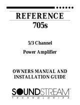
SYSlEMDIAGRAVI#
1
SYSTEM
DlAGRAM#
2
Channels of input: 4
Bridged
Channels: none
Subwoofer
Channel Impedance: 2 ohms
High
l%wr/l-iigh
Current
Ming:
High
I%WI
SOUNDSTRE4M”
C H N 0
L
0
0
I E 8
i&t+
Fmel
Connections
REFERENCE 405
24
d3Dct
Battom
Panel
Stich
Settings
HGH
FWR~]
HGH CUXENT
cIwwaS3&4
CI-wwELs1&2
SUClUWEL
SlEm
J1
rmfa
B\rppGs
[-a
HGH
PPGS
CH3&4J]CH
l&2
Irsur
6Yw6s
[-a
LOWS5
SLBCI-I
ra
CH
1.2.3or4
IWUT
M4N
FUSES
HGHP&S:
12dt3rocl
ldIGw%S:
12cf$oct
~c)vkS.S.
24
dB0d
I
I
ml
MONO:
lNWTFFKCMCH4
MY’0
IbJUlFROMCH2
cRCH2
Channels of input: 2
Bridged Channels: none
Subwofer
Channel Impedance: 4 ohms
High
Powrmigh
Current Setting: High Power
FLEE
-
-
-
SAELLIES
S&JELLIES
1
I-
t
-
I/
0
L
0
0
I
E
s
Et
XI
&mec#ons
REFERENCE 405
-ER
I\
t-E/ouNl
/
Bottom
Panel
hitch
Settings
ClWWELS3
&4
cII+wwS1&2
SUBCWVML
STEEO
I]
rvmJ0
I
sfERmJ~hmo
EiwYtxi
r.1
Law&
fM=XS
[-a
HGH
PKS
BVXS
ra
HGH
MS
SU3CH
ra
CH
1.2.30~4
CH3&4[aCH1&2
INRJl
l-m-w%S
12d3/mt
HWB:
12cfKkt
LWPGS:
24dBKkt
m
I
I
M3No: IfW_JlFFRC%lCH4
MCNO
lNWFRC%lC+l2
CI?CH2
MAN FUSES

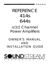
SYSTEM
DlAGRAM#
3
/
SYSTE
M
DIAGRAM#
4
Channels of input:
6
EMdged
Channels: none
Subwofer Channel Impedance: 2 ohms
High
Power/High
Current Setting: High
her
*Using
outboard “dual amp
balancer”
to remotely
adjust
subwoofer
level.
Channels of input: 2
EMdged
Channels: 1
&
2,3
&
4
Subwofer Channel Impedance:
<
1 ohm
High
Power/l-iigh
Current Setting: High Current
SOUNDSTREAM.
t
P
c
H
N 0 L 0
0
I
E
s
Front
Pcnel
Connedions
REFERENCE 405
SOUNDSTREA’vl”
0
0
I
E
s
Et
&I
cuo&tim
REFERENCE 405
-
+
Lit&
WELLllES
I
12
dBDct
TO+ l2V
04TlER/
I/-
WELLES
12cfMM
I
12dBKkf
f-l
WEI
+
I\
HEPD
UNIl
/
24
dsloct
24 dBPct
I
HEAD
UW
I
Bottom
panel
shitch
settings
Bottom
Pcnel
Wtch
Settings
.SUBCWNNEL
HGHDWR~~
HGtCUrZREN’r
sl.8 cw+NEL
hws!Ii
I_
LawKS
SUICH~~
CH1.2.3cx4
INfUl
M4N FUSES
LCMRPGS:
24dfiQct
I
SLBcHpN\EL
HGH
FO’MR
HGtlCmM
Ct+WELS1&2
CHPNNL.53
&4
czl-tmNELs3&4
cHpNNLs1&2
SLBCMEL
smEo~,Mmo
Bmss
(~HGHPAS
CH38t4D]CHl&2
IW
STERO
m-1
MONO
STEFEo~jhm
BWBS
(
LOvmxs
BYPPGS
1-a
HGH
PPGS
BYP%S~~HGtiPpGs
SUBCti
I1
CH1.2.3orP
CH3&4~~CHl&2
INUT
INfwl
HlGwm:
12aDct
tiGt-PpGs~
12cfKkt
LCMW6S
24dE@cI
I
1
r5l
M3NO:
INRJT
FFROM
C+i
4
MC+0 lNUTFRCtvlCJi2
oRCH2
5

INSTALLATION
1. PLAN THE INSTALLATION
Before you go any further with the installation of the amplifier, map out the system
and the necessary wiring. Your work will be simplified if you have a plan of
attack. Consider all electrical requirements, as well as physical, such as amplifier
ventilation and availability of space.
2. SELECT OPERATING MODES (on underside)
The configuration switches are accessible by removing the plugs on the
underside of the amplifier. They allow you to determine the operating
configuration of the amplifier, including:
0
5 or 3 channels of input (via bridging)
0
normal (High Power) or low impedance (High Current) operation with the
subwoofer channel
0
number of channels of input to drive the amplifier
0
crossover activation for the subwoofer, front, and rear channels
A. Stereo/Bridged Mono (see System Diagrams
#1
-
4)
Each pair of the 4 channels rated at 25 watts each (12 volts) can be bridged
mono.
If running either pair of channels in mono, be sure to set the switch for the
appropriate pair to “mono.”
CONNECTION DIAGRAMS
BRIDGED MONO
+
L
-
-
R +
STEREO
+ L
-
-
R +
r/m
r\
m
,m
B
.
a
Crossover Settings
Each pair of the 4 channels rated at 25 watts each (12 volts) can be set to
operate either full range or high pass. To use the built-in high pass
crossover, select high pass. If you are using the mono channel full range or
with an external crossover, select bypass.
0
The mono channel can be set to operate either full range or low pass. To
use the low pass crossover, select low pass; to operate the channel up to
400 Hz (for use with an external crossover), select bypass.
C. High Power/High Current (mono channel)
The mono channel can be set to operate in either high power or high current
mode. Select the mode of operation as follows:
1 Ohm or higher
High Power
less than 1 Ohm
High Current
The REFERENCE405 subwoofer channel is designed to drive extremely low
impedances. Be sure that the High Power/High Current switch is in the
appropriate setting for best performance and maximum reliability.
D. Inputs (see System Diagrams
#I
-
4)
All five channels of the REFERENCE405 can be driven with
2,4,
or 6 channels of
input.
If your head unit has one or two pairs of outputs, you can drive all 5
channels of the amplifier.
Channels of Input
# of channels of
imut
I
Switch setting for each set of channels
I
3&4
I
Subwoofer
2
1
l&2
I
1, 2, 3 or
4
4
3&4
1,
2, 3
or
4
6
3&4
SUB CH
NOTE: Channels
I
&
2 are not listed. These channels must a/ways receive input
in order for operation of all 5 channels.
3. LOCATION OF THE AMPLIFIER
When mounting the amplifier, it should be securely mounted to either a panel in
the vehicle or an amp board or rack that is securely mounted to the vehicle. The
mounting location should be either in the passenger compartment or in the trunk
of the vehicle, away from moisture, stray or moving objects, and major electrical
components (electric motors, fuel pumps, etc.). To provide adequate ventilation,
mount the amplifier so there are at least 2 inches of freely circulating air above
and to the sides of it.
4. MOUNTING OF THE AMPLIFIER
1. Using the amplifier as a template, mark the mounting surface.
2. Remove the amplifier and drill the holes.
3. Mount the amplifier to the surface using the provided hardware.

~
5. WIRING
The only tool needed to make wire terminations at the amplifier will be a flat
blade-type screwdriver and either wire strippers or a knife. When baring wires for
connection to the amplifier, remove approximately
98”
of the insulation, insert
into the terminal block, and tighten the screw. Determine from the chart below
the minimum gauge power and ground wire for your application.
up to 5’ up to 10’
greater than
IO’
Soundstream Power40
Soundstream
Soundstream
or Power80 Power40 or Power80
Power40
(4 or 8 ga.) (4 or 8 ga.)
(4
gas)
Wiring Tips
0
Use grommets when running cables through any metal or sharp plastic
to prevent accidental shorting or shearing.
0
Be certain that the cables don’t interfere with normal operation of the
vehicle.
0
Choose the location of the audio cables carefully to prevent interference
with the vehicle’s high current circuits and vehicle management systems
(engine computers, relays, etc.).
1.
Carefully run the audio and remote turn-on cables to the amplifier.
2.
Connect the speakers as shown in “Selecting Operating Modes” in section
2. Use at least a 16 gauge speaker wire, preferably a flexible multi-strand
cable, such as Soundstream Speaker 160 or Speaker 120.
3.
Carefully run the positive power cable from the battery to a fuse or a
circuit breaker and then to the amplifier. Connect the lead to the battery
via either a fuse or circuit breaker within 18 inches of the battery. The fuse
or circuit breaker value should be 40 to 50 amps. Leave the fuse out or the
circuit breaker off until the installation is
othencvise
finished. If the circuit
breaker cannot be shut off manually, do not make the final power connection
until the installation is finished.
4.
Run a ground cable for the amplifier and securely connect it to a solid
chassis ground on the vehicle. The ground cable should be the same gauge
as the power cable.
5.
Double check each and every connection.
amplifier power LED is on and the source unit is playing, you should have
sound coming from the speakers.
6. LEVEL SETTING
The input levels are adjusted by means of the input level controls located
between the RCA inputs and the speaker outputs. When the amplifier is
operated in the mono/bridged mode, only the right channel input is active.
1.
Turn the amp’s input level controls to minimum position (fully counter-
clockwise).
2.
Set source unit volume to approximately 314 of full volume.
3.
While playing dynamic source material, slowly increase the amplifier’s
input level(s) until a near maximum undistorted level is heard in the
system.
NOTE:
The best Signal to Noise ratio is achieved when the amplifier
I
input gains are set between 500 mV and 2.5 V.
7. CROSSOVER ADJUSTMENTS
The REFERENCE405 incorporates a continuously variable staggered
asymmetrical electronic crossover. The high and low pass portions of the
crossover can be adjusted independent of one another. Follow the below
procedure to adjust the crossover:
1.
Make certain the crossover is activated (see Section
ZB,
Select
Operating Modes).
2.
Set crossover frequency adjustments to the 12 o’clock position.
3.
While listening to music, adjust the high pass frequency dial for the high
pass. Select a frequency high enough to prevent damage to the
speakers, yet low enough that you are able to retain midbass in the front
speakers.
4.
Adjust the subwoofer frequency control in the same way as the high
pass. This time, listen to bass. You should find a setting that will give
you a solid sound with minimum “boom” from resonating frequencies.
Note; Many times, the best results are achieved with the high pass
frequencies set higher than the low pass. This “staggered” setting
compensates for much of the midbass resonance inherent in the automobile
environment.
You may find it necessary to readjust the crossover after listening to the
system.
The correct settings are a combination of the capabilities of the
equipment and your listening preferences.
6.
Reconnect the fuse or circuit breaker. Power up the system and look at
the green and red
LEDs,
depending on the configuration, one should be lit.
The may be a 2
-
3 second delay from the time that the source unit is turned
on to the time that the LED on the amp turns on, which is normal. Once the
10

8. PROTECTION CIRCUITS
Your REFERENCE405 amplifier is protected against both overheating and short
circuits by means of the following circuits:
0
Main power supply fuses (2 at 20 amps each)
0
Smart Power Supply Thermal Rollback activating at
85OC.
0
A fail-safe thermal protection circuit activating at
95OC.
0
Speaker over-current protection relays (on the 4 x 25 watt channels).
Your amplifier also incorporates an innovative Fault Diagnosis system that
identifies a blown power supply fuse.
0
If you experience blown main power fuses, DO NOT increase values beyond
20 amp (each) fuses.
9. TROUBLESHOOTING
PROBLEM
No sound and
LEDs
are not lit
Fault LED
is lit
Repeatedly
blown amp fuse,
frequent activation of Smart
Power Supply Circuit or
speaker protection circuit
breakers
no sound from subwoofer
channel with 2 or 4 channels of
input
no sound from channels
3
&
4 with 2 channels of input
CAUSE
0
no power or ground at
amp
0
no remote turn-on signal
0
blown fuse near battery
0
amp power supply fuse is
blown
0
check speaker
configuration, amp may be
in “High Power” mode, put
amp into “High Current”
mode if speaker load is
less than 2 Ohms (see
Section 2, Selecting
Operating Modes)
0
speaker or leads may be
shorted
0
verify adequate amplifier
ventilation
0
check input settings on
bottom of amplifier--switch
should be set at inputs
“I,
2, 3 or 4” unless using
external inputs
l
check input settings on
bottom of amplifier--switch
should be set at inputs “1
&
2”
10. SERVICE
Your Soundstream amplifier is protected by a limited warranty. Please read the
enclosed warranty card.
11.
SPECIFICATIONS
POWER OUTPUT
25 watts x 4 plus 100 watts x 1 (4 ohms, 12
V)
50 watts x 1 (4 ohms, 12 V, High
Current)
40 watts x 4 plus 120 watts x 1 (4 ohms, 14.4
V)
200 watts x 1 (2 ohms)
>240
watts x 1 (1 or
l/2
ohm)
0
THD:
~0.1%
0
Signal to Noise:
>lOO
dB
0
Frequency Response: 20 Hz to 20
kHz
+/-
0.5
dB
(dedicated sub channel): 20 Hz to 400 Hz
+/-
0.5
dB
0
Bandwidth: 15 Hz to 50
kHz
(dedicated sub channel): 15 Hz to 1
kHz
0
Stereo Separation:
>90
dB
0
Damping:
>200
0
Input Sensitivity: 100
mV
-
2.5 V
a
Input Impedance: 12 k ohms
Crossover Specifications:
0
High Pass: 12 dB/octave, Continuously Variable
from 60
-
240 Hz (front
&
rear)
0
Low Pass: 24 dB/octave, Continuously Variable
from 30
-
120 Hz
Dimensions: 16” W x
9-l/2”
D x
2-l/4”
H
11
12

SPEAKER WIRING CONFIGURATIONS
Two4OhmSpeakers
InFaralld=2Ohms
Tw4ohmspeakers
InSeties=8Ohm
Four 4 Ohm Speakers
In
Furallel
=
1
Ohm
SOUNDSTREAM TECHNOLOGIES
120 Blue Ravine Road l Folsom
.
California 95630 USA
tel 916.351
.I288
fax 916.351.0414
ver2.07a
13
/