Page is loading ...

Servitec Mini
10.10.2022-Rev. C
GB
Operating manual
Original operating manual

Notes on the operating manual
2
— English Servitec Mini —
10.10.2022-Rev. C
English
Contents
1 Notes on the operating manual .................................................................... 4
2 Liability and guarantee ................................................................................. 4
3 Safety.............................................................................................................. 5
3.1 Personnel requirements .................................................................................. 5
3.2 Personal protective equipment ...................................................................... 6
3.3 Intended use ...................................................................................................... 6
3.4 Inadmissible operating conditions ................................................................ 6
3.5 Residual risks ..................................................................................................... 7
4 Description of the device............................................................................... 8
4.1 Overview ............................................................................................................ 8
4.2 Identification ..................................................................................................... 8
4.3 Function ............................................................................................................. 9
4.4 Scope of delivery ............................................................................................... 9
4.5 Optional equipment and accessories ............................................................ 10
5 Technical data ................................................................................................ 10
6 Installation ..................................................................................................... 11
6.1 Incoming inspection ......................................................................................... 12
6.2 Preparatory work .............................................................................................. 12
6.3 Connection......................................................................................................... 13
6.4 Execution............................................................................................................ 13
6.4.1 Installation of the isolation valves .............................................. 14
6.4.2 Wall mounting ............................................................................... 15
6.4.3 Hydraulic connection .................................................................... 16
7 Commissioning .............................................................................................. 17
7.1 Requirements for initial commissioning ....................................................... 17
7.2 Adjusting the filling pressure of the system ................................................. 17
7.3 Commissioning ................................................................................................. 18
7.4 Installation and commissioning certificate ................................................... 18

Notes on the operat
ing manual
Servitec Mini —
10.10.2022-Rev. C
English — 3
8 Operation ....................................................................................................... 19
8.1 Automatic mode ............................................................................................... 19
8.2 Stop mode .......................................................................................................... 19
8.3 Restarting ........................................................................................................... 19
9 Controller ....................................................................................................... 20
9.1 Operator panel .................................................................................................. 20
9.2 Messages ............................................................................................................ 21
9.3 Reset ................................................................................................................... 22
10 Maintenance .................................................................................................. 22
10.1 Maintenance schedule ..................................................................................... 23
10.2 Cleaning ............................................................................................................. 24
11 Disassembly ................................................................................................... 25
12 Disposal .......................................................................................................... 26
13 Annex ............................................................................................................. 27
13.1 Reflex Customer Service .................................................................................. 27
13.2 Conformity and standards ............................................................................... 27
13.3 Guarantee .......................................................................................................... 27
Servitec Mini
10.10.2022-Rev. C

Notes on the operating manual
4
— English Servitec Mini —
10.10.2022-Rev. C
1 Notes on the operating manual
This operating manual is an important aid for ensuring the safe and reliable functioning of the device.
Reflex Winkelmann GmbH accepts no liability for any damage resulting from failure to observe the
information in this operating manual. In addition to the requirements set out in this operating
manual, national statutory regulations and provisions in the country of installation must also be
complied with (concerning accident prevention, environment protection, safe and professional work
practices, etc.).
Notice!
Every person installing this equipment or performing any other work at the equipment is
required to carefully read
this operating manual prior to commencing work and to comply
with its instructions. The manual is to be provided to the product operator and must be
stored near the product for access at any time.
2 Liability and guarantee
The device has been built according to the state of the art and recognised safety rules. Nevertheless,
its use can pose a risk to life and limb of personnel or third persons as well as cause damage to the
system or other property.
It is not permitted to make any modifications at the device, such as to the hydraulic system or the
circuitry.
The manufacturer shall not be liable nor shall any warranty be honoured if the cause of any claim
results from one or more of the following causes:
• Improper use of the device.
• Unprofessional commissioning, operation, service, maintenance, repair or installation of the
device.
• Failure to observe the safety information in this operating manual.
• Operation of the device with defective or improperly installed safety/protective equipment.
• Opening the housing of the electrical controller.
• Failure to perform maintenance and inspection work according to schedule.
• Use of unapproved spare parts or accessories.
Prerequisite for any warranty claims is the professional installation and commissioning of the device.
Note!
Arrange for specialist personnel to carry out commissioning and annual maintenance.

Safety
Servitec Mini —
10.10.2022-Rev. C
English — 5
3 Safety
The following symbols and signal words are used in this operating manual.
DANGER
Danger of death and/or serious damage to health
• The sign, in combination with the signal word 'Danger', indicates imminent danger; failure to
observe the safety information will result in death or severe (irreversible) injuries.
WARNING
Serious damage to health
• The sign, in combination with the signal word 'Warning', indicates imminent danger; failure
to observe the safety information can result in death or severe (irreversible) injuries.
CAUTION
Damage to health
• The sign, in combination with the signal word 'Caution', indicates danger; failure to observe
the safety information can result in minor (reversible) injuries.
ATTENTION
Damage to property
• The sign, in combination with the signal word 'Attention', indicates a situation where damage
to the product itself or objects within its vicinity can occur.
Note!
This symbol, in combination with the signal word 'Note', indicates useful tips and
recommendations for efficient handling of the product.
3.1 Personnel requirements
Only specialist personnel or specifically trained personnel may install and operate the equipment.
The electric connections and the wiring of the device must be executed by a specialist in accordance
with all applicable national and local regulations.

Safety
6
— English Servitec Mini —
10.10.2022-Rev. C
3.2 Personal protective equipment
Use the prescribed personal protective equipment as required (e.g. ear protection, eye protection,
safety shoes, helmet, protective clothing, protective gloves) when working at the system in which the
device is installed.
Information on personal protective equipment requirements is set out in the relevant national
regulations of the respective country of operation.
3.3 Intended use
The device is used in facility systems for stationary heating and cooling circuits. The devices may be
used only in systems that are sealed against corrosion and with the following water types:
• Non-corrosive.
• Chemically non-aggressive.
• Non-toxic.
Minimise the entry of atmospheric oxygen throughout the facility system and into the make-up water.
Note!
Ensure the quality of the make
-up water as specified by national regulations.
•
For example, VDI 2035 or SIA 384-1.
3.4 Inadmissible operating conditions
The device is not suitable for the following applications:
• Outdoor operation.
• For use with mineral oils.
• For use with flammable media.
• For use with distilled water.
• For use with fully desalinated water.
Note!
It is not permitted to make any modifications to the hydraulics or the circuitry.

Safety
Servitec Mini —
10.10.2022-Rev. C
English — 7
3.5 Residual risks
The device has been manufactured using state-of-the-art technology. Despite this, residual risks
cannot be excluded.
WARNING
Risk of fire due to open ignition sources
The device housing is made of combustible material and is heat-sensitive.
• Avoid heat and ignition sources (flames or sparks).
CAUTION
Risk of burns on hot surfaces
Hot surfaces in heating systems can cause burns to the skin.
• Wear protective gloves.
• Please place appropriate warning signs in the vicinity of the device.
CAUTION
Risk of injury due to pressurised liquid
If installation, removal or maintenance work is not carried out correctly, there is a risk of burns and
other injuries at the connection points, if pressurised hot water or hot steam suddenly escapes.
• Ensure proper installation, removal or maintenance work.
• Ensure that the system is de-pressurised before performing installation, removal or
maintenance work at the connection points.
CAUTION
Risk of injury due to heavy device weight
The device weight may cause physical injury or accidents.
• If necessary, work with a second person during assembly or disassembly.
ATTENTION
Device damage during transport
If the device is not transported correctly, it may be damaged.
• Use suitable covers to protect the connections against damage.

Description o
f the device
8
— English Servitec Mini —
10.10.2022-Rev. C
4 Description of the device
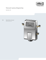
The Servitec Mini is a water degassing system for use in small systems of up to 1 m3 system volume.
4.1 Overview
1 Venting grille
2 Hinge for folding up
3 Controller
4 Gas-rich water inlet
5 Dirt trap
6 Degassed water outlet
7 Folds up in the direction of the arrow
4.2 Identification
The nameplate provides information on manufacturer, year of manufacture, part number and
technical data. The nameplate is located on the rear side of the controller inside the system.
Information on the type plate
Meaning
Type Device name
Serial No. Serial number
min. / max. allowable pressure P Minimum/maximum permissible pressure
min. / max. continuous operating temperature Minimum/maximum continuous operation
temperature
Year built Year of manufacture

Description of the device
Servitec Mini —
10.10.2022-Rev. C
English — 9
4.3 Function
1 Vacuum is drawn 3 Discharge
2 Injection 4 Idling time
The Reflex Servitec Mini can degas the system water in a spray tube. Gas-rich water is sprayed into the
spray tube via a nozzle. A pump sucks the water out of the spray tube and transports it into the
system. The system is set up so that the pump draws more water from the pipe that can flow through
the nozzle. The result is a vacuum in the spray tube, that causes the degassing effect. When the pump
switches off, water flows into the spray tube and pushes the driven out gas to the outside via a special
valve.
4.4 Scope of delivery
The scope of delivery is described in the shipping document for the initial shipment and the content is
shown on the packaging.
Immediately after receipt of the goods, please check the shipment for completeness and damage.
Please notify us immediately of any transport damage.
Basic degassing equipment:
• Device
• 2 ball valves for the degassing connections
• Operating manual
• Drilling template and set of screws for wall mounting

Technical data
10
— English Servitec Mini —
10.10.2022-Rev. C
4.5 Optional equipment and accessories
The following optional equipment and accessories are available for use with this device:
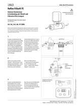
• Fillcontrol Plus Compact with external pressure sensor for make-up with water.
• Fillsoft/Fillsoft zero for softening/desalinating the make-up water from the potable water
system.
Note!
Separate operating manuals are supplied with accessories.
Note!
Connection to the heating or chilled water system must be performed externally.
5 Technical data
Permissible flow temperature: 60 °C
Permissible ambient temperature: 0 °C - 45 °C
Permissible operating overpressure: 4.0 bar
Degree of discharge, dissolved gases: ≤ 90 %
Degree of discharge, free gases: 100 %
Degree of protection: IP 54
Electrical power: 60 W
Electrical supply: 230 V; 50 Hz
Electrical current consumption: 0.3 A
Electrical voltage control unit: 230 V
Sound pressure level: 55 dB
Weight: 5.6 kg
Height: 420 mm
Width: 295 mm
Depth: 220 mm
Connection: 1/2 "
System volume: 1 m³
Operating pressure: 0.5 - 2.5 bar
Permissible operating overpressure: 4 bar
Max. permissible operating temperature: 60 °C

Installation
Servitec Mini —
10.10.2022-Rev. C
English — 11
6 Installation
DANGER
Risk of serious injury or death due to electric shock.
If live parts are touched, there is risk of life-threatening injuries.
• Ensure that the supply cable to the device is disconnected and secured against being
switched back on.
• Ensure that the system is secured and cannot be reactivated by other persons.
• Ensure that installation work for the electric connection of the device is carried out by an
electrician, and in compliance with electrical locally applicable electrical engineering
regulations.
CAUTION
Risk of injury due to pressurised liquid
If installation, removal or maintenance work is not carried out correctly, there is a risk of burns and
other injuries at the connection points, if pressurised hot water or hot steam suddenly escapes.
• Ensure proper installation, removal or maintenance work.
• Ensure that the system is de-pressurised before performing installation, removal or
maintenance work at the connection points.
CAUTION
Risk of burns on hot surfaces
Hot surfaces in heating systems can cause burns to the skin.
• Wear protective gloves.
• Please place appropriate warning signs in the vicinity of the device.
CAUTION
Risk of injury due to falls or bumps
Bruising from falls or bumps on system components during installation.
• Wear personal protective equipment (helmet, protective clothing, gloves, safety boots).
Note!
Confirm that
installation and start-up have been carried out correctly using the installation
and commissioning certificate. This action is a prerequisite for the making of warranty
claims.
–
Have the Reflex Customer Service carry out commissioning and the annual
maintenance.

Installation
12
— English Servitec Mini —
10.10.2022-Rev. C
6.1 Incoming inspection
Prior to shipping, this device was carefully inspected and packed. Damages during transport cannot be
excluded.
Proceed as follows:
1. Upon receipt of the goods, check the shipment for
• completeness and
• possible transport damage.
2. Document any damage.
3. Contact the forwarding agent to register your complaint.
6.2 Preparatory work
Condition of the delivered device:
• Check all screw connections of the device for tight seating. Tighten the screws as necessary.
Preparing the connection of the device to the plant system:
• Barrier-free access to the plant system.
• Level and solid installation surface for the device.
• Frost-free, well-ventilated room.
– Room temperature > 0 - 45 °C.
• Electric connection.
– 230 V~, 50 Hz, 16 A with upstream ELCB (tripping current: 0.03 A).

Installation
Servitec Mini —
10.10.2022-Rev. C
English — 13
6.3 Connection
Basic system variant Servitec Mini
1 Servitec Mini
2 Gas-rich water
3 Degassed water
• Connection 2 x DN 15
• Max. pipe length 5m
Note!
Shut
-off valves must be used at the connection point to the pipe network.
Note!
We recommend connection to the existing pipe network using a flexible hose connection
(especially in buildings with high noise abatement requirements).
6.4 Execution
Note!
The screw connections at the device may loosen when the device is moved to another
location.
–
Prior to using the device check the screw connections for proper seating and sealing.
Note!
Avoid leaks at the connections.
–
When connecting the device to the facility system, ensure that the connections for
degassing and make-up are not twisted.

Installation
14
— English Servitec Mini —
10.10.2022-Rev. C
Proceed as follows:
• Connect the device on the return side of the system.
– In this manner, you ensure that the device is operated within the permissible pressure and
temperature ranges.
• In the case of a system with return flow admixture or a hydraulic switching point, connect the
device upstream of the switching point.
– In doing so, you guarantee water degassing in the "V" main volume flow at temperatures
≤ 60 °C.
CAUTION – damage due to improper connection! Bear in mind that the device may be subject to
additional loads through the connection of piping or hose connections to the system. Ensure that all
connections to the system are free from stresses. If necessary, provide support structures for the pipes.
CAUTION – Damage to property caused by leaks! Leaks in the connection pipes to the device can cause
damage to property within the system. Use only connection pipes with adequate resistance against
the system temperature.
Proceed as follows:
1 Mount the device on the wall, see chapter 6.4.3 "Hydraulic connection" on page 16 .
2 Complete the water side connections from the device to the system, .
Note!
When connecting, ensure the valves and supply element options of the connecting pipes
can be operated.
6.4.1 Installation of the isolation valves
1 Isolation valve with filter insert
2 Isolation valve
3 Connection pipe
The connection pipes (3, blue) are pre-
assembled in the factory. The shut-off valves (1)
and (2) are fitted to the device on-site prior to
wall mounting.

Installation
Servitec Mini —
10.10.2022-Rev. C
English — 15
6.4.2 Wall mounting
ATTENTION
Damage due to sound and noise transfer to building parts
• Do not install the device on false or stud walls that could act as a sound box or resonating
body.
1 Drilling template
2 Set of screws
Use the holes provided at the rear of the
housing to attach the device at the wall.
Dependent on the wall properties, the fastening
materials must be checked and if necessary
adapted prior to installation.
Note!
Use the enclosed drilling template and set of screws for wall mounting.
1
. Attach the drilling template to the wall with sticky tape.
2
. Drill the holes for attaching the device
3
. Remove the drilling template.
4
Hang the device on the wall.

Installation
16
— English Servitec Mini —
10.10.2022-Rev. C
6.4.3 Hydraulic connection
Install the 'DC' degassing pipes as shown below:
Comply with the following points:
• Prevent overloading of the dirt trap in the device resulting from coarse dirt.
• Install the gas-rich degassing line upstream of the gas-poor degassing line (when viewed in the
system flow direction).
• Preferably install on the return side of the system.
– The water temperature must be in the range of 0 °C – 60 °C to ensure sufficient degassing
capacity.

Commissioning
Servitec Mini —
10.10.2022-Rev. C
English — 17
7 Commissioning
Note!
Arrange for specialist personnel to carry out commissioning and annual maintenance.
7.1 Requirements for initial commissioning
The device will be ready for commissioning when the tasks described in the "Installation" chapter have
been completed.
• The device is securely mounted.
• The connections of the device to the system have been created and plant system pressure
maintenance is operational.
– One degassing pipe to the plant system (device outlet).
– One degassing pipe from the plant system (device inlet).
• If required, the connection pipes of the device have been purged and cleaned of welding residue
and dirt prior to commissioning.
• The plant system is filled with water and the majority of the gas has been vented.
– Circulation through the entire plant system is thus ensured.
7.2 Adjusting the filling pressure of the system
Before the Servitec Mini is commissioned, the system must be filled. The volume of the Servitec Mini
must be allowed for in the system. Proceed as follows:
1 Open the device ball valves.
– Water flows in and air escapes via the degassing valve.
2 Determine the filling pressure for the system:
– Filling pressure “pF”: pF[bar] = p0 + 0.3 bar
– Prepressure “pF”: pF[bar] = pstat + 0.2 bar
– Static pressure “pstat”: pstat [bar] = Height [metre] / 10
3 Check the filling pressure of the system.
4 Fill the system with water.
– Until the necessary filling pressure is reached.

Commissioning
18
— English Servitec Mini —
10.10.2022-Rev. C
7.3 Commissioning
Link the device to the voltage supply:
1 Connect the device plug-in contact to the voltage supply.
2 Press “Auto” on the controller's operator panel.
Note!
The system pressure is automatically measured by the integrated pressure sensor.
•
During commissioning the Servitec Mini always measures the actual system pressure
and generates a message if the pressure is less than the target system pressure by
more than 0.3 bar.
•
If the system pressure is less than 0.5 bar, a low water error is triggered. Increase the
system pressure accordingly.
Note!
We recommend rechecking of the pressure maintenance target value (system pressure) 2
weeks after commissioning of the Servitec Mini and if necessary, replenishing of the
system.
7.4 Installation and commissioning certificate
Note!
The
installation and commissioning certificate can be found at the end of the operating
manual.

Operation
Servitec Mini —
10.10.2022-Rev. C
English — 19
8 Operation
8.1 Automatic mode
Automatic mode includes the two operating modes continuous degassing and interval degassing.
Note!
The starting time of the
degassing processes is specified based on the time at the very first
start.
To reset and for new setting of the start time, see chapter
9.3 "Reset" on page 22 .
Continuous degassing
This mode is started during first commissioning by pressing the Auto button. Multiple degassing
cycles without pause times are carried out over a fixed period of several hours during the day. The
daily start time is set based on the time of the initial commissioning.
Interval degassing
This mode comprises repeating intervals. There is a pause time between the intervals. Once
continuous degassing has completed, interval degassing starts automatically.
8.2 Stop mode
On the controller, press ‘Stop’ to activate stop mode. The Auto LED of the control panel goes out, the
Stop LED lights up.
Except for the display of information, the device is non-functional in Stop mode. Function monitoring
is stopped. The vacuum pump is switched off.
Note!
The system triggers
an error message if Stop mode is activated for more than 4 hours.
8.3 Restarting
Note!
Recommissioning after a long shut
-down takes place by pressing the ‘Auto’ button.

Controller
20
— English Servitec Mini —
10.10.2022-Rev. C
9 Controller
9.1 Operator panel
1 Degassing LED
• Lights up green during the injection
function, .
2 Water level LED
• Lights up red if a warning exists
3 Pump LED
• Lights up green during operation
4 Stop button/LED
• For stop mode
• Lights up yellow
5 Auto button/LED
• For continuous operation
• Acknowledge error messages
• Lights up green
6 Error LED
• Lights up red if an error exists
/