Asus PRIME H270-PLUS User manual
- Category
- Motherboards
- Type
- User manual
This manual is also suitable for

Motherboard
PRIME H270-PLUS

ii
E12007
First Edition
September 2016
Copyright © 2016 ASUSTeK COMPUTER INC. All Rights Reserved.
No part of this manual, including the products and software described in it, may be reproduced,
transmitted, transcribed, stored in a retrieval system, or translated into any language in any form or by any
means, except documentation kept by the purchaser for backup purposes, without the express written
permission of ASUSTeK COMPUTER INC. (“ASUS”).
Product warranty or service will not be extended if: (1) the product is repaired, modied or altered, unless
such repair, modication of alteration is authorized in writing by ASUS; or (2) the serial number of the
product is defaced or missing.
ASUS PROVIDES THIS MANUAL “AS IS” WITHOUT WARRANTY OF ANY KIND, EITHER EXPRESS
OR IMPLIED, INCLUDING BUT NOT LIMITED TO THE IMPLIED WARRANTIES OR CONDITIONS OF
MERCHANTABILITY OR FITNESS FOR A PARTICULAR PURPOSE. IN NO EVENT SHALL ASUS, ITS
DIRECTORS, OFFICERS, EMPLOYEES OR AGENTS BE LIABLE FOR ANY INDIRECT, SPECIAL,
INCIDENTAL, OR CONSEQUENTIAL DAMAGES (INCLUDING DAMAGES FOR LOSS OF PROFITS,
LOSS OF BUSINESS, LOSS OF USE OR DATA, INTERRUPTION OF BUSINESS AND THE LIKE),
EVEN IF ASUS HAS BEEN ADVISED OF THE POSSIBILITY OF SUCH DAMAGES ARISING FROM ANY
DEFECT OR ERROR IN THIS MANUAL OR PRODUCT.
SPECIFICATIONS AND INFORMATION CONTAINED IN THIS MANUAL ARE FURNISHED FOR
INFORMATIONAL USE ONLY, AND ARE SUBJECT TO CHANGE AT ANY TIME WITHOUT NOTICE,
AND SHOULD NOT BE CONSTRUED AS A COMMITMENT BY ASUS. ASUS ASSUMES NO
RESPONSIBILITY OR LIABILITY FOR ANY ERRORS OR INACCURACIES THAT MAY APPEAR IN THIS
MANUAL, INCLUDING THE PRODUCTS AND SOFTWARE DESCRIBED IN IT.
Products and corporate names appearing in this manual may or may not be registered trademarks or
copyrights of their respective companies, and are used only for identication or explanation and to the
owners’ benet, without intent to infringe.
Offer to Provide Source Code of Certain Software
This product contains copyrighted software that is licensed under the General Public License (“GPL”),
under the Lesser General Public License Version (“LGPL”) and/or other Free Open Source Software
Licenses. Such software in this product is distributed without any warranty to the extent permitted by the
applicable law. Copies of these licenses are included in this product.
Where the applicable license entitles you to the source code of such software and/or other additional data,
you may obtain it for a period of three years after our last shipment of the product, either
(1) for free by downloading it from http://support.asus.com/download
or
(2) for the cost of reproduction and shipment, which is dependent on the preferred carrier and the location
where you want to have it shipped to, by sending a request to:
ASUSTeK Computer Inc.
Legal Compliance Dept.
15 Li Te Rd.,
Beitou, Taipei 112
Taiwan
In your request please provide the name, model number and version, as stated in the About Box of the
product for which you wish to obtain the corresponding source code and your contact details so that we
can coordinate the terms and cost of shipment with you.
The source code will be distributed WITHOUT ANY WARRANTY and licensed under the same license as
the corresponding binary/object code.
This offer is valid to anyone in receipt of this information.
ASUSTeK is eager to duly provide complete source code as required under various Free Open Source
Software licenses. If however you encounter any problems in obtaining the full corresponding source
code we would be much obliged if you give us a notication to the email address [email protected], stating
the product and describing the problem (please DO NOT send large attachments such as source code
archives, etc. to this email address).

iii
Contents
Safety information ...................................................................................................... iv
About this guide ......................................................................................................... iv
Package contents ....................................................................................................... vi
PRIME H270-PLUS specications summary ........................................................... vi
Chapter 1: Product introduction
1.1 Before you proceed ...................................................................................... 1-1
1.2 Motherboard overview ................................................................................. 1-1
1.3 Central Processing Unit (CPU) .................................................................. 1-10
1.4 System memory .......................................................................................... 1-11
Chapter 2: BIOS information
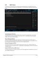
2.1 Managing and updating your BIOS ............................................................. 2-1
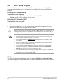
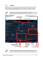
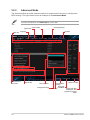
2.2 BIOS setup program ..................................................................................... 2-5
2.3 Exit menu .................................................................................................... 2-10
Appendix
Notices ..................................................................................................................... A-1
ASUS contact information ...................................................................................... A-4

iv
Safety information
Electrical safety
• To prevent electrical shock hazard, disconnect the power cable from the electrical outlet
before relocating the system.
• When adding or removing devices to or from the system, ensure that the power cables
for the devices are unplugged before the signal cables are connected. If possible,
disconnect all power cables from the existing system before you add a device.
• Before connecting or removing signal cables from the motherboard, ensure that all power
cables are unplugged.
• Seek professional assistance before using an adapter or extension cord. These devices
could interrupt the grounding circuit.
• Ensure that your power supply is set to the correct voltage in your area. If you are not
sure about the voltage of the electrical outlet you are using, contact your local power
company.
• If the power supply is broken, do not try to x it by yourself. Contact a qualied service
technician or your retailer.
Operation safety
• Before installing the motherboard and adding components, carefully read all the manuals
that came with the package.
• Before using the product, ensure all cables are correctly connected and the power cables
are not damaged. If you detect any damage, contact your dealer immediately.
• To avoid short circuits, keep paper clips, screws, and staples away from connectors,
slots, sockets and circuitry.
• Avoid dust, humidity, and temperature extremes. Do not place the product in any area
where it may be exposed to moisture.
• Place the product on a stable surface.
• If you encounter technical problems with the product, contact a qualied service
technician or your retailer.
About this guide
This user guide contains the information you need when installing and conguring the
motherboard.
How this guide is organized
This guide contains the following parts:
• Chapter 1: Product introduction
This chapter describes the features of the motherboard and the new technology it
supports. It includes descriptions of the switches, jumpers, and connectors on the
motherboard.
• Chapter 2: BIOS information
This chapter discusses changing system settings through the BIOS Setup menus.
Detailed descriptions for the BIOS parameters are also provided.

v
Where to nd more information
Refer to the following sources for additional information and for product and software
updates.
1. ASUS websites
The ASUS website provides updated information on ASUS hardware and software
products. Refer to the ASUS contact information.
2. Optional documentation
Your product package may include optional documentation, such as warranty yers,
that may have been added by your dealer. These documents are not part of the
standard package.
Conventions used in this guide
To ensure that you perform certain tasks properly, take note of the following symbols used
throughout this manual.
DANGER/WARNING: Information to prevent injury to yourself when
completing a task.
CAUTION: Information to prevent damage to the components when
completing a task
IMPORTANT: Instructions that you MUST follow to complete a
task.
NOTE: Tips and additional information to help you complete a task.
Typography
Bold text Indicates a menu or an item to select.
Italics
Used to emphasize a word or a phrase.
<Key> Keys enclosed in the less-than and greater-than sign
means that you must press the enclosed key.
Example: <Enter> means that you must press the Enter or
Return key.
<Key1> + <Key2> + <Key3> If you must press two or more keys simultaneously, the key
names are linked with a plus sign (+).

vi
(continued on the next page)
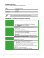
PRIME H270-PLUS specications summary
CPU LGA1151 socket for 7th/6th Generation Intel® Core™ i7/ i5/ i3
Pentium® and Celeron® processors
Supports 14nm CPU
Supports Intel® Turbo Boost Technology 2.0*
* Intel® Turbo Boost Technology 2.0 support depends on the CPU types.
** Refer to www.asus.com for Intel® CPU support list.
Chipset Intel® H270 Chipset
Memory 4 x DIMM, maximum 64 GB, DDR4 2400*/ 2133**MHz, non-ECC, un-
buffered memory
Dual-channel memory architecture
Supports Intel® Extreme Memory Prole (XMP)
* Due to Intel® chipset limitation, DDR4 2400MHz memory frequency is only
supported by 7th Generation Intel® processors. Higher memory modules will
run at the maximum transfer rate of DDR4 2400MHz.
** Due to Intel® chipset limitation, DDR4 2133MHz and higher memory modules
on 6th Generation Intel® processors will run at the maximum transfer rate of
DDR4 2133MHz.
*** Refer to www.asus.com for the latest Memory QVL (Qualied Vendors List).
Expansion slots 1 x PCI Express 3.0/2.0 x16 slot (at x16 mode)
1 x PCI Express 3.0/2.0 x16 slot (max. at x4 mode, compatible with PCIe x1
and x4 devices)
4 x PCI Express 3.0/2.0 x1 slots
Graphics Integrated graphics processor - Intel® HD Graphics support
Multi-VGA output support:HDMI,DVI-D, and RGB ports
- Supports HDMI 1.4b with max. resolution 4096 x 2160@24Hz / 2560 x
1600@60Hz
- Supports DVI-D with max. resolution of 1920 x 1200@60Hz
- Supports RGB with max. resolution 1920 x 1200@60Hz
Supports Intel® InTru™ 3D/Quick Sync Video/Clear Video HD Technology/
Insider™
Supports up to 3 displays simultaneously
Maximum shared memory of 1024MB(for iGPU exclusively)
Package contents
Check your motherboard package for the following items.
Motherboard ASUS PRIME H270-PLUS motherboard
Cables 2 x Serial ATA 6.0 Gb/s cables
Accessories 1 x I/O Shield
2 x M.2 Screws
Application DVD Support DVD
Documentation User Guide
If any of the above items is damaged or missing, contact your retailer.

vii
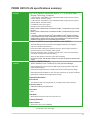
PRIME H270-PLUS specications summary
(continued on the next page)
Storage Intel® H270 Express Chipset with RAID 0, 1, 5, 10 and Intel Rapid
Storage Technology 15 support
- 1 x M.2 Socket 3 with M Key, type 2242/2260/2280 storage devices support
(SATA mode & X4 PCIE mode)*
- 1 x M.2 Socket 3 with M Key, type 2242/2260/2280 storage devices support
(SATA mode & X2 PCIE mode)**
- 6 x SATA 6.0 Gb/s ports (gray)
- Ready for Intel® Optane memory***
* When a device in SATA mode is installed on the M.2_1 socket, SATA_1 port cannot
be used.
** When a device in SATA mode is installed on the M.2_2 socket, SATA_6 port cannot
be used.
*** Only M.2_1 socket can support Intel® Optane Memory. Intel® Optane Technology
is only supported when using 7th Generation Intel® processors. Before using Intel®
Optane memory modules, ensure that you have updated your motherboard drivers
and BIOS to the latest version from ASUS support website.
Audio Realtek® ALC887 8-channel high denition audio CODEC
- Audio Shielding: Ensures precision analog/digital separation and greatly
reduces multi-lateral interference
- Dedicated audio PCB layers: Separate layers for left and right channels to
guard the quality of the sensitive audio signals
- Premium Japanese audio capacitors: Provide warm, natural and immersive
sound with exceptional clarity and delity.
- Supports jack-detection and front panel jack-retasking
* Choose the chassis with HD audio module in front panel to support 8-channel audio
output.
ASUS unique
features
ASUS 5X PROTECTION III
- ASUS SafeSlot Core: Fortied PCIe Slot prevents damage
- ASUS LANGuard: Protects against LAN surges, lightning strikes and static-
electricity discharges!
- ASUS Overvoltage Protection: World-class circuit-protecting power design
- ASUS Stainless-Steel Back I/O: 3X corrosion-resistance for greater durability!
- ASUS DIGI+ VRM: 6 Phase digital power design
Superb Performance
M.2 onboard
- The latest transfer technologies with up to 32Gb/s data transfer speeds
ASUS Fan Xpert 2+
- Ultimate cooling and quietness
ASUS EPU
- EPU
UEFI BIOS
- Most advanced options with fast response time
Gaming Scenario
Audio Features
- Audio that roars on the battleeld

viii
ASUS unique
features
ASUS Exclusive Features
- ASUS Ai Charger
- ASUS AI Suite 3
EZ DIY
UEFI BIOS EZ Mode
- Featuring friendly graphics user interface
- ASUS CrashFree BIOS 3
- ASUS EZ Flash 3
Q-Design
- ASUS Q-DIMM
- ASUS Q-Slot
ASUS Quiet
Thermal Solution Quiet Thermal Design
- ASUS ASUS Fan Xpert 2+
- Stylish Fanless Design: PCH Heat-sink & MOS Heat-sink solution
Back Panel I/O
ports
1 x PS/2 keyboard
1 x PS/2 mouse port
1 x HDMI port
1 x DVI-D port
1 x RGB port
1 x LAN (RJ45) ports
4 x USB 3.0/2.0 ports ( blue, Type A)
2 x USB 2.0/1.1 ports
3-Jack 8-Channel Audio I/O ports
Internal I/O
connectors
2 x USB 3.0/2.0 connectors support additional 4 USB ports (19-pin)
2 x USB 2.0/1.1 connectors support additional 4 USB ports
6 x SATA 6.0 Gb/s connectors (gray)
2 x M.2 Socket 3 (for M Key)
1 x 4-pin CPU Fan connector (PWM mode)*
3 x 4-pin Chassis Fan connectors for 3-pin (DC mode) and 4-pin (PWM mode)
coolers control*
1 x Front panel audio connector (AAFP)
1 x Mono Out header
1 x System panel connector**
1 x S/PDIF out header
1 x 24-pin EATX Power connector
1 x 8-pin EATX 12V Power connector
1 x TPM header
1 x COM header
1 x Clear CMOS jumper
* By default, the CPU/Chassis Q-Fan control setting is set to Auto mode, which
detects the CPU and chassis fans installed and changes the control mode
automatically.
** Chassis intrusion header is built in the system panel connector.
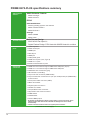
PRIME H270-PLUS specications summary
(continued on the next page)

ix
Specications are subject to change without notice.
BIOS features 128 Mb Flash ROM, UEFI AMI BIOS, PnP, DMI3.0, WfM2.0, SM
BIOS 3.0, ACPI 6.0, Multi-language BIOS, ASUS EZ Flash 3,
CrashFree BIOS 3, F11 EZ Tuning Wizard, F6 Qfan Control, F3
My Favorites, Last Modied log, F12 PrintScreen, and ASUS
DRAM SPD (Serial Presence Detect) memory information
Manageability WfM 2.0, DMI 3.0, WOL by PME, PXE
Support DVD Drivers
ASUS utilities
EZ Update
Anti-virus software (OEM version)
Operating System
Support
Windows® 10 (64-bit)
Windows® 8.1 (64-bit)*
Windows® 7 (64-bit/32-bit)*
* Windows® 8.1 64-bit and Windows® 7 32/64-bit are only supported when using
6th Generation Intel® processors.
Form factor ATX form factor: 12.0 in. x 8.7 in. (30.5 cm x 22.1cm)
PRIME H270-PLUS specications summary

ASUS PRIME H270-PLUS
1-1
Product introduction
1
1.1 Before you proceed
Take note of the following precautions before you install motherboard components or change
any motherboard settings.
• Unplugthepowercordfromthewallsocketbeforetouchinganycomponent.
• Beforehandlingcomponents,useagroundedwriststraportouchasafelygrounded
objectorametalobject,suchasthepowersupplycase,toavoiddamagingthemdue
to static electricity.
• Beforeyouinstallorremoveanycomponent,ensurethattheATXpowersupplyis
switched off or the power cord is detached from the power supply. Failure to do so
maycauseseveredamagetothemotherboard,peripherals,orcomponents.
Unplugthepowercordbeforeinstallingorremovingthemotherboard.Failuretodosocan
cause you physical injury and damage motherboard components.
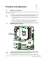
1.2 Motherboard overview
Place this
side towards
the rear of the
chassis
PRIME H270-PLUS
PCIEX16_1
PCIEX16_2
PCIEX1_3
PCIEX1_2
PCIEX1_1
PCIEX1_4
ALC
887
M.2_1(SOCKET3)
M.2_2(SOCKET3)
RTL
8111H
RTL
2166
USB1112 USB1314
AAFP
SPDIF_OUT CLRTC
EATXPWR
BATTERY
Super
I/O
2280 2260 2242
2280 2260 2242
KBMS
DVI
VGA
22.1cm(8.7in)
DDR4 DIMM_A1 (64bit, 288-pin module)
DDR4 DIMM_A2 (64bit, 288-pin module)
DDR4 DIMM_B1 (64bit, 288-pin module)
DDR4 DIMM_B2 (64bit, 288-pin module)
SATA6G_6 SATA6G_5
LAN_USB910
USB3_78
USB3_56
HDMI
CHA_FAN2
CPU_FAN
CHA_FAN1
CHA_FAN3
30.5cm(12in)
LGA1151
DIGI
+VRM
COM
MONO_OUT
EATX12V
USB3_12
USB3_34
Intel®
H270
128Mb
BIOS
ASM1480
PANEL
AUDIO
SATA6G_2 SATA6G_1
SATA6G_4 SATA6G_3
LANGuard
PCIE SATA
M.2_2
IRST
X2 V X
PCIE SATA
M.2_1
IRST
X4 V V
TPM
21 3 42
9 85 61011121415 13
1
2
5
6
7
17
16
17
16
16

1-2
Chapter 1: Product introduction
1.2.1 Layout contents
Connectors/Jumpers/Slots/LED Page
1. ATXpowerconnectors(24-pinEATXPWR,8-pinEATX12V) 1-2
2. CPUandchassisfanconnectors(4-pinCPU_FAN,4-pinCHA_FAN1~3) 1-3
3. Intel®LGA1151CPUsocket 1-3
4. DDR4DIMMslots 1-3
5. USB3.0connectors(20-1pinUSB3_12,USB3_34) 1-3
6. M.2Socket3 1-4
7. Intel®H270SerialATA6.0Gb/sconnector(7-pinSATA6G_1~6) 1-4
8. ClearRTCRAM(2-pinCLRTC) 1-4
9. Systempanelconnector(20-3pinPANEL) 1-5
10. USB2.0connectors(10-1pinUSB1112,USB1314) 1-5
11. TPMconnector(14-1pinTPM) 1-6
12. Serialportconnectors(10-1pinCOM) 1-6
13. Monooutheader(2-pinMONO_OUT) 1-6
14. Frontpanelaudioconnector(10-1pinAAFP) 1-6
15. Digitalaudioconnector(4-1pinSPDIF_OUT) 1-6
16. PCIExpress3.0/2.0x1slots 1-7
17. PCIExpress3.0/2.0x16slots 1-7
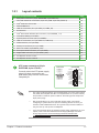
ATX power connectors (24-pin
EATXPWR, 8-pin ATX12V)
CorrectlyorienttheATXpowersupply
plugs into these connectors and
pushdownrmlyuntiltheconnectors
completelyt.
EATX12V
+12V DC
+12V DC
+12V DC
+12V DC
GND
GND
GND
GND
EATXPWR
PIN 1
PIN 1
GND
+5 Volts
+5 Volts
+5 Volts
-5 Volts
GND
GND
GND
PSON#
GND
-12 Volts
+3 Volts
+3 Volts
+12 Volts
+12 Volts
+5V Standby
Power OK
GND
+5 Volts
GND
+5 Volts
GND
+3 Volts
+3 Volts
• Forafullyconguredsystem,werecommendthatyouuseapowersupply
unit(PSU)thatcomplieswithATX12VSpecication2.0(orlaterversion)
andprovidesaminimumpowerof350W.ThisPSUtypehas24-pinand
8-pinpowerplugs.
• WerecommendthatyouuseaPSUwithhigherpoweroutputwhen
conguringasystemwithmorepower-consumingdevicesorwhenyou
intendtoinstalladditionaldevices.Thesystemmaybecomeunstableor
may not boot up if the power is inadequate.
•
If you are uncertain about the minimum power supply requirement for your
system,refertotheRecommendedPowerSupplyWattageCalculator
at http://support.asus.com/PowerSupplyCalculator/PSCalculator.
aspx?SLanguage=en-us for details.

ASUS PRIME H270-PLUS
1-3
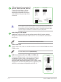
CPU and chassis fan connectors (4-
pin CPU_FAN, 4-pin CHA_FAN1~3)
Connect the fan cables to the fan
connectorsonthemotherboard,
ensuring that the black wire of each
cable matches the ground pin of the
connector.
CHA FAN PWM
CHA FAN IN
CHA FAN PWR
GND
CPU_FAN CHA_FAN1
CPU FAN PWM
CPU FAN IN
CPU FAN PWR
GND
CHA_FAN3
CHA FAN PWM
CHA FAN IN
CHA FAN PWR
GND
CHA_FAN2
GND
CHA FAN PWR
CHA FAN IN
CHA FAN PWM
Donotforgettoconnectthefancablestothefanconnectors.Insufcientair
owinsidethesystemmaydamagethemotherboardcomponents.Theseare
notjumpers!Donotplacejumpercapsonthefanconnectors!TheCPU_FAN
connectorsupportsaCPUfanofmaximum1A(12W)fanpower.
Intel® LGA1151 CPU socket
Install Intel®LGA1151CPUintothissurfacemountLGA1151socket,whichis
designedfor7th/6th Generation Intel®Core™i7/i5/i3,Pentium®,andCeleron®
processors.
Formoredetails,refertoCentral Processing Unit (CPU).
DDR4 DIMM slots
Install2GB,4GB,8GB,and16GBunbufferednon-ECCDDR4DIMMsintothese
DIMMsockets.
Formoredetails,refertoSystem memory.
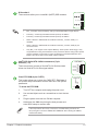
USB 3.0 connectors (20-1 pin USB3_12, USB3_34)
ConnectaUSB3.0moduletoanyoftheseconnectors
foradditionalUSB3.0frontorrearpanelports.These
connectorscomplywithUSB3.0specicationsand
providesfasterdatatransferspeedsofupto5Gbps,faster
chargingtimeforUSB-chargeabledevices,optimizedpower
efciency,andbackwardcompatibilitywithUSB2.0
USB3_12
USB3+5V
IntA_P1_SSRX-
IntA_P1_SSRX+
GND
IntA_P1_SSTX-
IntA_P1_SSTX+
GND
IntA_P1_D-
IntA_P1_D+
GND
PIN 1
USB3+5V
IntA_P2_SSRX-
IntA_P2_SSRX+
GND
IntA_P2_SSTX-
IntA_P2_SSTX+
GND
IntA_P2_D-
IntA_P2_D+
USB3_34
USB3+5V
IntA_P1_SSRX-
IntA_P1_SSRX+
GND
IntA_P1_SSTX-
IntA_P1_SSTX+
GND
IntA_P1_D-
IntA_P1_D+
GND
PIN 1
USB3+5V
IntA_P2_SSRX-
IntA_P2_SSRX+
GND
IntA_P2_SSTX-
IntA_P2_SSTX+
GND
IntA_P2_D-
IntA_P2_D+

1-4
Chapter 1: Product introduction
M.2 socket 3
These sockets allow you to install M.2(NGFF)SSDmodules.
M.2_2(SOCKET3)
2280 2260 2242
M.2_1(SOCKET3)
2280 2260 2242
PRIME Z270-P M.2(SOCKET3)s
PRIME Z270-P
• M.2_1/2Socket3supportMKeyandtype2242/2260/2280storagedevices.
• TheM.2_1socketsupportsdatatransferspeedupto32Gb/s.
• TheM.2_2socketsupportsdatatransferspeedupto16Gb/s.
• WhenadeviceinSATAmodeisinstalledontheM.2_1socket,SATA_1is
disabled.
• WhenadeviceinSATAmodeisinstalledontheM.2_2socket,SATA_6port
cannot be used.
• OnlyM.2_1cansupportIntel®OptaneMemory.Intel®OptaneTechnologyisonly
supported when using 7th Generation Intel®processors.BeforeusingIntel®Optane
memorymodules,ensurethatyouhaveupdatedyourmotherboarddriversand
BIOStothelatestversionfromASUSsupportwebsite.
Intel® H270 Serial ATA 6.0Gb/s connectors (7-pin
SATA6G_1~6)
TheseconnectorsconnecttoSerialATA6.0Gb/sharddisk
drivesviaSerialATA6.0Gb/ssignalcables.
GND
RSATA_TXP
RSATA_TXN
GND
RSATA_RXN
RSATA_RXP
GND
SATA6G
Clear RTC RAM (2-pin CLRTC)
ThisheaderallowsyoutocleartheCMOSRTCRAMdataof
thesystemsetupinformationsuchasdate,time,andsystem
passwords.
To erase the RTC RAM:
1. TurnOFFthecomputerandunplugthepowercord.
2. Useametalobjectsuchasascrewdrivertoshortthetwo
pins.
3. PlugthepowercordandturnONthecomputer.
4. Holddownthe<Del> key during the boot process and
enterBIOSsetuptore-enterdata.
CLRTC
+3V_BAT
GND
PIN 1
Ifthestepsabovedonothelp,removetheonboardbatteryandshortthe
twopinsagaintocleartheCMOSRTCRAMdata.AfterclearingtheCMOS,
reinstall the battery.

ASUS PRIME H270-PLUS
1-5
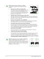
System panel connector (20-3 pin F_PANEL)
Thisconnectorsupportsseveralchassis-mounted
functions.
• System power LED (4-pin +PWR_LED-)
This4-pinconnectorisforthesystempowerLED.
ConnectthechassispowerLEDcabletothis
connector.ThesystempowerLEDlightsupwhen
youturnonthesystempower,andblinkswhen
the system is in sleep mode.
PLED+
PLED-
PWR
Ground
+5V
Ground
Ground
Speaker
CASEOPEN
HDD_LED+
HDD_LED-
GND
Reset
+5V
PLED+
PLED-
GND
PIN 1
+PWR_LED-
+PWR_LED-
SPEAKER
PANEL
+HDD_LED-
PWR_SW
RESET
* Requires an ATX power supply
CHASSIS
• Hard disk drive activity LED (2-pin +HDD_LED-)
This2-pinconnectorisfortheHDDActivityLED.ConnecttheHDDActivity
LEDcabletothisconnector.TheHDDLEDlightsuporasheswhendatais
readfromorwrittentotheHDD.
• System warning speaker (4-pin SPEAKER)
This4-pinconnectorisforthechassis-mountedsystemwarningspeaker.
The speaker allows you to hear system beeps and warnings.
• ATX power button/soft-off button (2-pin PWR_SW)
Thisconnectorisforthesystempowerbutton.Pressingthepowerbutton
turns the system on or puts the system in sleep or soft-off mode depending
ontheoperatingsystemsettings.Pressingthepowerswitchformorethan
foursecondswhilethesystemisONturnsthesystemOFF.
• Reset button (2-pin RESET)
This 2-pin connector is for the chassis-mounted reset button for system
reboot without turning off the system power.
• Chassis intrusion header (2-pin CHASSIS)
This connector is for a chassis-mounted intrusion detection sensor or switch.
Connect one end of the chassis intrusion sensor or switch cable to this
connector.Thechassisintrusionsensororswitchsendsahigh-levelsignalto
thisconnectorwhenachassiscomponentisremovedorreplaced.Thesignal
isthengeneratedasachassisintrusionevent.
USB 2.0 connectors (10-1 pin USB1112, USB1314)
ConnectaUSBmodulecabletoanyofthese
connectors,theninstallthemoduletoaslotopeningat
thebackofthesystemchassis.TheseUSBconnectors
complywithUSB2.0specicationsandsupportsupto
480Mbpsconnectionspeed.
USB+5V
USB_P11-
USB_P11+
GND
NC
USB+5V
USB_P12-
USB_P12+
GND
USB1112
PIN 1
USB+5V
USB_P13-
USB_P13+
GND
NC
USB+5V
USB_P14-
USB_P14+
GND
USB1314
PIN 1

1-6
Chapter 1: Product introduction
TPM connector (14-1 pin TPM)
ThisconnectorsupportsaTrustedPlatformModule(TPM)system,
whichcansecurelystorekeys,digitalcerticates,passwords,and
data.ATPMsystemalsohelpsenhancenetworksecurity,protects
digitalidentities,andensuresplatformintegrity.
TPM
PIN 1
+3VSB
S_PCIRST#_TBD
GND
C_PCICLK_TPM
+3V
+3V
TPM_PD#
F_SERIRQ
F_FRAME#
F_LAD3
F_LAD2
F_LAD1
F_LAD0
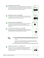
Serial port connector (10-1 pin COM)
Thisconnectorisforaserial(COM)port.Connecttheserialport
modulecabletothisconnector,theninstallthemoduletoaslot
opening at the back of the system chassis.
PIN 1
COM
DCD
TXD
GND
RTS
RI
RXD
DTR
DSR
CTS
Mono out header (2-pin MONO_OUT)
Thisinternalmonooutheaderallowsconnectiontoaninternal,
low power speaker for basic system sound capability. The
subsystemiscapableofdrivingaspeakerloadof4Ohmsat2
Watts(rms).
R_OUT-
R_OUT+
PIN 1
MONO_OUT
Front panel audio connector (10-1 pin AAFP)
Thisconnectorisforachassis-mountedfrontpanelaudioI/O
modulethatsupportsHDaudiostandard.Connectoneendofthe
frontpanelaudioI/Omodulecabletothisconnector.
AAFP
AGND
NC
SENSE1_RETUR
SENSE2_RETUR
PORT1 L
PORT1 R
PORT2 R
SENSE_SEND
PORT2 L
HD-audio-compliant
pin definition
• Werecommendthatyouconnectahigh-denitionfrontpanelaudio
moduletothisconnectortoavailofthemotherboard’shigh-denitionaudio
capability.
• Ifyouwanttoconnectahigh-denitionfrontpanelaudiomoduletothis
connector,settheFrontPanelTypeitemintheBIOSsetupto[HDAudio].
Bydefault,thisconnectorissetto[HDAudio].
Digital audio connector (4-1 pin SPDIF_OUT)
ThisconnectorisforanadditionalSony/PhilipsDigitalInterface
(S/PDIF)port.ConnecttheS/PDIFOutmodulecabletothis
connector,theninstallthemoduletoaslotopeningatthebackof
the system chassis.
SPDIF_OUT
+5V
SPDIFOUT
GND

ASUS PRIME H270-PLUS
1-7
• InsingleVGAcardmode,usethePCIe3.0x16_1slot(gray)foraPCIExpressx16
graphics card to get better performance.
• WerecommendthatyouprovidesufcientpowerwhenrunningCrossFireX™mode.
• ConnectachassisfantothemotherboardconnectorlabeledCHA_FAN1/2/3when
usingmultiplegraphicscardsforbetterthermalenvironment.
VGA conguration
PCI Express operating mode
PCIe 3.0 x16_1 (gray) PCIe 3.0 x16_2
Single VGA/PCIe card x16(Recommendedforsingle
VGAcard) N/A
Dual VGA/PCIe cards x16 x4
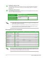
PCI Express 3.0/2.0 x1 slots
ThismotherboardhasfourPCIExpress3.0/2.0x1slotsthatsupportPCIExpress
x1networkcards,SCSIcards,andothercardsthatcomplywiththePCIExpress
specications.
PCI Express 3.0/2.0 x16 slots
ThismotherboardsupportstwoPCIExpress3.0/2.0x16graphiccardsthatcomply
withthePCIExpressspecications.
IRQ assignments for this motherboard
WhenusingPCIcardsonsharedslots,ensurethatthedriverssupport“ShareIRQ”orthat
thecardsdonotneedIRQassignments.Otherwise,conictswillarisebetweenthetwoPCI
groups,makingthesystemunstableandthecardinoperable.
A B C D
HDAudioController shared – – –
XHCI shared – – –
SATAController shared – – –
LANController shared – – –
PCIEx1_1 – – – shared
PCIEx1_2 shared – – –
PCIEx1_3 – shared – –
PCIEx1_4 – – shared –
PCIEx16_1 shared – – –
PCIEx16_2 shared – – –
M.2_1 shared – – –
M.2_2 shared – – –

1-8
Chapter 1: Product introduction
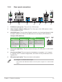
1.2.2 Rear panel connectors
4. Line In port (light blue).Thisportconnectsthetape,CD,DVDplayer,orotheraudio
sources.
5. Line Out port (lime).Thisportconnectsaheadphoneoraspeaker.In4.1-channel,
5.1-channel,and7.1-channelcongurations,thefunctionofthisportbecomesFront
SpeakerOut.
6. Microphone port (pink). This port connects a microphone.
To congure a 7.1-channel audio output:
UseachassiswithHDaudiomoduleinthefrontpaneltosupporta7.1-channelaudio
output.
LAN port
Speed
LED
Activity Link
LED
Activity/Link LED Speed LED
Status Description Status Description
Off Nolink OFF 10Mbpsconnection
Orange Linked ORANGE 100Mbpsconnection
Orange(Blinking) Dataactivity GREEN 1Gbps connection
Orange(Blinking
thensteady)
Readytowake
upfromS5mode
10 68 7
2 4 53
8
1
11 9
1. PS/2 Mouse port (green).ThisportisforaPS/2mouse.
2. Video Graphics Adapter (VGA) port.This15-pinportisforaVGAmonitororother
VGA-compatibledevices.
3. LAN (RJ-45) port.ThisportallowsGigabitconnectiontoaLocalAreaNetwork(LAN)
throughanetworkhub.RefertothetablebelowfortheLANportLEDindications.
LAN port LED indications

ASUS PRIME H270-PLUS
1-9
Audio 2.1, 4.1, 5.1 or 7.1-channel conguration
Port Headset
2.1-channel 4.1-channel 5.1-channel 7.1-channel
LightBlue
(Rearpanel) Line In RearSpeakerOut RearSpeakerOut RearSpeakerOut
Lime(Rearpanel) LineOut FrontSpeakerOut FrontSpeakerOut FrontSpeakerOut
Pink(Rearpanel) MicIn MicIn Bass/Center Bass/Center
Lime(Frontpanel) — — — SideSpeakerOut
Fora7.1-channelspeakersetup,refertothe7.1-channelcongurationinthetable.
7. USB 2.0 portsThesefour4-pinUniversalSerialBus(USB)portsareforUSB2.0/1.1
devices.
8. USB 3.0 ports.Thesefour9-pinUniversalSerialBus(USB)portsconnecttoUSB
3.0/2.0devices.
• DuetoUSB3.0controllerlimitations,USB3.0devicescanonlybeusedundera
Windows®OSenvironmentandafterUSB3.0driverinstallation.
• USB3.0devicescanonlybeusedfordatastorage.
• WestronglyrecommendthatyouconnectUSB3.0devicestoUSB3.0portsforfaster
andbetterperformancefromyourUSB3.0devices.
9. HDMI port.ThisportisforaHigh-DenitionMultimediaInterface(HDMI)connector,
andisHDCPcompliantallowingplaybackofHDDVD,Blu-ray,andotherprotected
content.
10. DVI-D port.ThisportisforanyDVI-Dcompatibledevice.
DVI-DcannotbeconvertedtooutputfromRGBSignaltoCRTandisnotcompatiblewith
DVI-I.
11. PS/2 keyboard port (purple).ThisportisforaPS/2keyboard.

1-10
Chapter 1: Product introduction
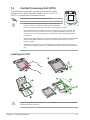
1.3 Central Processing Unit (CPU)
ThismotherboardcomeswithasurfacemountLGA1151socket
designedforthe7th/6thGenerationIntel®Core™i7/Core™i5/
Core™i3,Pentium®andCeleron®processors.
UnplugallpowercablesbeforeinstallingtheCPU.
• EnsurethatyouinstallthecorrectCPUdesignedforthe
LGA1151socketonly.DONOTinstallaCPUdesignedfor
LGA1150,LGA1155andLGA1156socketsontheLGA1151socket.
• Uponpurchaseofthemotherboard,ensurethatthePnPcapisonthesocketand
thesocketcontactsarenotbent.ContactyourretailerimmediatelyifthePnPcap
ismissing,orifyouseeanydamagetothePnPcap/socketcontacts/motherboard
components.
• Keepthecapafterinstallingthemotherboard.ASUSwillprocessReturnMerchandise
Authorization(RMA)requestsonlyifthemotherboardcomeswiththecaponthe
LGA1151socket.
• Theproductwarrantydoesnotcoverdamagetothesocketcontactsresultingfrom
incorrectCPUinstallation/removal,ormisplacement/loss/incorrectremovalofthePnP
cap.
Installing the CPU
1
4
ApplytheThermalInterfaceMaterialtotheCPUheatsinkandCPUbeforeyouinstallthe
heatsink and fan if necessary.
2
3
A
B
A
B
C
D
5
4
4
5

ASUS PRIME H270-PLUS
1-11
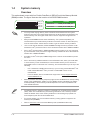
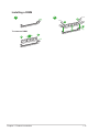
1.4 System memory
Overview
ThismotherboardcomeswithfourDoubleDataRate4(DDR4)DualInlineMemoryModule
(DIMM)sockets.ThegureillustratesthelocationoftheDDR4DIMMsockets:
Channel Sockets
ChannelA DIMM_A1&DIMM_A2
ChannelB DIMM_B1&DIMM_B2
• YoumayinstallvaryingmemorysizesinChannelAandChannelB.Thesystem
mapsthetotalsizeofthelower-sizedchannelforthedual-channelconguration.Any
excessmemoryfromthehigher-sizedchannelisthenmappedforsingle-channel
operation.
• AlwaysinstallDIMMswiththesameCASlatency.Foroptimalcompatibility,we
recommendthatyouinstallmemorymodulesofthesameversionordatecode(D/C)
fromthesamevendor.Checkwiththeretailertogetthecorrectmemorymodules.
• DuetoIntel®chipsetlimitation,DDR42133MHzandhighermemorymoduleson6th
Generation Intel®processorswillrunatthemaximumtransferrateofDDR42133MHz
• DuetoIntel®chipsetlimitation,DDR42400MHzmemoryfrequencyisonlysupported
by 7th Generation Intel®processors.Highermemorymoduleswillrunatthemaximum
transferrateofDDR42400MHz.
• AccordingtoIntel®CPUspec,DIMMvoltagebelow1.35Visrecommendedtoprotect
theCPU.
• Duetothememoryaddresslimitationon32-bitWindows®OS,whenyouinstall4GB
ormorememoryonthemotherboard,theactualusablememoryfortheOScanbe
about3GBorless.Foreffectiveuseofmemory,werecommendthatyoudoanyofthe
following:
- Useamaximumof3GBsystemmemoryifyouareusinga32-bitWindows®OS.
- Installa64-bitWindows®OSifyouwanttoinstall4GBormoreonthe
motherboard.
- Formoredetails,refertotheMicrosoft® support site at http://support.microsoft.
com/kb/929605/en-us.
• Memorymoduleswithmemoryfrequencyhigherthan2133MHzanditscorresponding
timingortheloadedX.M.P.ProleisnottheJEDECmemorystandard.Thestability
andcompatibilityofthesememorymodulesdependontheCPU’scapabilitiesand
otherinstalleddevices.
• ThedefaultmemoryoperationfrequencyisdependentonitsSerialPresenceDetect
(SPD),whichisthestandardwayofaccessinginformationfromamemorymodule.
Underthedefaultstate,somememorymodulesforoverclockingmayoperateata
lowerfrequencythanthevendor-markedvalue.
• Forsystemstability,useamoreefcientmemorycoolingsystemtosupportafull
memoryload(4DIMMs).
• Refertowww.asus.comforthelatestMemoryQVL(QualiedVendorsList)
DIMM_A1
DIMM_A2
DIMM_B1
DIMM_B2
Page is loading ...
Page is loading ...
Page is loading ...
Page is loading ...
Page is loading ...
Page is loading ...
Page is loading ...
Page is loading ...
Page is loading ...
Page is loading ...
Page is loading ...
Page is loading ...
Page is loading ...
Page is loading ...
Page is loading ...
Page is loading ...
-
 1
1
-
 2
2
-
 3
3
-
 4
4
-
 5
5
-
 6
6
-
 7
7
-
 8
8
-
 9
9
-
 10
10
-
 11
11
-
 12
12
-
 13
13
-
 14
14
-
 15
15
-
 16
16
-
 17
17
-
 18
18
-
 19
19
-
 20
20
-
 21
21
-
 22
22
-
 23
23
-
 24
24
-
 25
25
-
 26
26
-
 27
27
-
 28
28
-
 29
29
-
 30
30
-
 31
31
-
 32
32
-
 33
33
-
 34
34
-
 35
35
-
 36
36


Asus PRIME H270-PLUS User manual
- Category
- Motherboards
- Type
- User manual
- This manual is also suitable for
Ask a question and I''ll find the answer in the document
Finding information in a document is now easier with AI
Related papers
-
Asus PRIME Z270M-PLUS/BR User manual
-
Asus PRIME H270-PRO User manual
-
-
-
Asus PRIME B365M-K/CSM User manual
-
Asus PRIME H270M-PLUS User manual
-
Asus PRIME Q270M-C User manual
-
Asus ROG Strix G13CH User manual
-
Asus PRIME B250-PLUS User manual
-
Asus PRIME Z270-A User manual