Page is loading ...

1
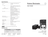
IPA T RLY4 • Setup Guide
This guide provides instructions for an experienced installer to install the Extron IPA T RLY4 relay
accessory and to make all connections.
The IPA T RLY4 is an IPLink
®
Accessory product. The relay accessory consists of four output relays with normally open (when the relay is
de-energized) (NO) and normally closed (NC) contacts.
The relay accessory converts a solid state (up to 12 VDC) signal, from a source such as the Flex I/O port of an Extron IPL T SF24 or the
digital I/O port of an MLC 104 IP Plus, to a relay contact closure. The relay contacts can handle up to 24 VAC or 24 VDC as a tally signal,
contact closure signal, or control signal to drive devices in your system, such as a lighting system (gure 1) or remote screens. The relay
contacts are protected by an overvoltage circuit.
IPA T RLY4
1 2 3 4 C
INPUTS
COM 3
LAN
UID# 093012052
POWER
12V
.5A MAX
COM 2
1
COM1
TX RX TX RX
I/O
2
3
4
COM2
Extron
IPL T SF24
Ethernet Control
Interface
Extron
IPA T RLY4
Relay Accessory
NO C NC
NO C NC NO C NC
NO C NC
RELAY 1
RELAY 2
RELAY 3
RELAY 4
Lighting System
Front
Rear
Extr
on
12
V Power
Supply
+12 VDC
(Common)
Figure 1. Typical IPA T RLY 4 Application
The compact IPA T RLY4 can be concealed out of the way anywhere in your system with the included hook and loop fastener strip.
Connections
NOTE: The 5-pole captive screw input connector and four 3-pole captive screw output connectors are included with the unit, but you
must supply the cable. Extron recommends the CTL Series cable, available non-plenum and plenum bulk rolls and plenum pre-cut
lengths.
IPA T RLY4
1 2 3 4 C
INPUTS
NO C NC
NO C NC NO C NC NO C NC
RELAY 1
RELAY 2
RELAY 3
RELAY 4
AA
BB BB BB BB
Figure 2. IPA T RLY4 Connections
Input Connections
A
Inputs — Connect the 12 VDC source to the common voltage (C) terminal of the 5-pole captive screw connector. Connect the
appropriate input terminal (1 through 4) to the digital output(s) of the IPL T SF24, MLC 104 IP Plus, or other device.
IMPORTANT:
Go to www.extron.com for the complete
user guide, installation instructions, and
specifications bef
ore connecting the
pr
oduct to the po
wer source.

2
IPA T RLY4 • Setup Guide (Continued)
ATTENTION:
• Connect +12 VDC to the C pin only and connect the return to one or all of the Input pins (1 through 4) for the relays that you
will use. Reversing the connections can damage the power supply.
• Raccordez une source +12Vcc uniquement à la broche C du connecteur et raccordez le circuit de retour à une ou plusieurs
broches d’entrée (1 à 4) pour les relais utilisés. Inverser les raccordements pourrait endommager la source d’alimentation.
• Observe proper polarity when making connections to the Power port on the MLC 104 IP Plus controller. Miswiring can
damage the port.
• Veillez à respecter la polarité appropriée lorsque vous effectuez des raccordements au port d’alimentation du contrôleur
MLC 104 IP Plus. Une erreur de raccordement pourrait endommager le port.
NOTES:
• Connect the I/O control line to the Input 1 terminal for relay 1, Input 2 for relay 2, and so on.
• Figure 3 is a wiring diagram of a typical application: an Extron MLC 104 IP Plus controlling an IPA T RLY4 relay function (see
the MLC 104 Plus Series User Guide for information on conguring the MLC to control the IPA T RLY4).
• Figure 4 shows an application that includes an external power supply and an Extron IPCP Pro Dual-NIC Controller. When
the relay accessory is connected to an IO port of an IPCP Pro module, ground the external power supply to the IO port
ground pin on the control processor.
IPA T RLY4
1 2 3 4 C
INPUTS
1
2
3
GROUND
+12V OUT
CM
GROUND
IR OUT
GROUND
SCP
GROUND
Tx
Rx
DISPLAY
RS-232/IR
A B C D E
COMM LINK
LAN
PRESS TAB WITH
TWEEKER TO REMOVE
A B
MLS
RS-232
POWER
12V
DIGITAL
I/O
IR IN
Tx
GROUND
Rx
+12V IN
MLC 104 IP Plus
Right Side
IPA T RLY4
Front Panel
+12 VDC
Relay 1
Relay 2
Relay 3
Figure 3. Wiring Diagram for Connection to an MLC 104 IP Plus
R
LAN
GTx Rx GTx Rx
COM 2 COM 3
RELAYS
2143CC
COM 1
GTx Rx
RTS CTS
IR/SERIAL
1
SG
2
SG
1234G
DIGITAL I/O
eBUS
+V +S -S G
PWR OUT = 6W
AV LAN 2
AV LAN 1
AV LAN 3
IPA T RLY4
1 2 3 4 C
INPUTS
INPUTS
INPUTS
INPUTS
INPUTS
INPUTS
INPUTS
INPUTS
INPUTS
US
Ground
all devices
.
– Return
+12 VDC input
Ridged
Smooth
1A MAX
100-240V 50-60Hz
External
12 VDC
Power Supply
G
C
2134
IPCP Pro Control Processor with Internal Power Supply
(w
ithin another device)
IPA T RLY4
Figure 4. Wiring Diagram for Connection to an IPCP Pro Control Processor with Internal Power Supply

3
Output Connections
B
Outputs (see figure 1 on page 1) — For each relay:
For the normally open contacts, connect a device between the NO and C terminals of the 3-pole captive screw connectors.
For the normally closed contacts, connect a device between the NC and C terminals of the 3-pole captive screw connectors.
NOTE: Figure 5 shows wiring diagrams for a typical application: an Extron IPA T RLY4 driving a screen controllers of various
types. These are examples only. Your equipment may have different wiring requirements (see the manual from the applicable
manufacturer for specific wiring instructions).
NO C NC
NO C NC NO C NC NO C NC
RELAY 1
RELAY 2
RELAY 3
RELAY 4
NO C NC
NO C NC NO C NC NO C NC
RELAY 1
RELAY 2
RELAY 3
RELAY 4
UP DOWN STOP
Typical Stewart Low Voltage Controller*
COMMON
RED BLACK
Typical Da-Lite or Draper Low Voltage Controller
WHITE (DA-LITE)
BLUE (DRAPER)
IPA T RLY4 IPA T RLY4
✝
Figure 5. Wiring Diagrams for Connection to a Screen Controller (See the NOTES below)
NOTES:
• * For a typical Stewart screen controller, a momentary closure on relay 1, 2, or 3 causes the screen to move up, down, or
stop.
•
=
For a typical Da-Lite or Draper screen controller, a momentary closure on relay 1 or 2 causes the screen to move up or
down. A momentary closure on relay 3 causes the screen to stop in its current position.
Use 1N4001 or equivalent diodes (not included) for reverse bias protection.
Recommended diode specifications:
• 100 mA maximum through diode
• 50 V maximum reverse bias
Operation
When an input signal is applied to one of the relays, the signal toggles the state of that IPA T RLY4 output relay; the relay NO contacts
close, routing the signal for the connected device, and its NC contacts open, interrupting the signal for the connected device. See the
chart below for clarication.
I/O mode I/O state
Relay state
NO NC
Output
On (closed) Closed Open
Off (open Open Closed

/