Page is loading ...

WC88 PTO WOOD CHIPPER
OWNER’S MANUAL
WC88
28/03/2017
2017

INTRODUCTION 3
INTENDED USE 3
SPECIFICATIONS 3
SAFETY 4
ASSEMBLY 6
UNPACKING 6
INFEED CHUTE PANELS 6
INFEED CHUTE ROUND EDGE BAR 8
INFEED ROLLER CONTROL HANDLE 8
INFEED ROLLER LINKAGE ARM 9
DISCHARGE CHUTE 9
CHIPPER BASE 10
HARDWARE 10
HYDRAULIC OIL 10
PTO SHAFT LENGTH 11
OPERATION 12
START UP 12
DISCHARGE CHUTE ADJUSTMENT 12
DISCHARGE CHUTE DEFLECTOR 13
CHIPPING 13
STOPPING 14
INFEED ROLLER CONTROL 15
MAINTENANCE & SERVICE 16
REPLACING BLADES 16
SHARPENING BLADES 17
SETTING BED PLATE GAP 18
ADJUSTING DRIVE BELT TENSION 20
REPLACING DRIVE BELTS 21
GREASABLE BEARINGS 23
PARTS LIST 24
PARTS DIAGRAMS 27
NOTES 34!
Page of 134

Dear Woodland Mills Customer,
Congratulations and thank you for choosing the Woodland MillsTM WC88 wood chipper! It
was designed to be the best valued PTO wood chipper on the market. Please take the time
to read through the manual for detailed instructions on assembly, operation and
maintenance. Following the procedures and recommendations in this manual will ensure
you yield maximum performance and safety from the WC88 wood chipper.
For any technical questions or replacement parts, please contact Woodland MillsTM
OWNER'S RECORD
Please take a moment to record the following information about your wood
chipper. If you need to call for assistance, please be ready to provide your
model and serial numbers. This information will allow us to help you more
quickly when you call.
MODEL NUMBER
SERIAL NUMBER
DATE OF PURCHASE
Page of 234

INTRODUCTION
INTENDED USE
Woodland Mills chippers are designed for acreage owners to aid in chipping natural,
untreated wood only. Materials that are processed may contain chemicals or by-products
that could corrode the machine or damage it, resulting in safety concerns.
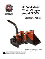
SPECIFICATIONS
"
"
SPECIFICATIONS
WC88
PTO Shear Pin
M8 X 45mm Bolt - Class 8.8 (Grade 5)
Drive System
PTO
Transport
3 Point Hitch
Minimum HP Required (at the PTO)
30
Flywheel Size
24" (610mm) Diameter / 120 lbs (54kgs)
Blades
(4) 2.75” x 4.5” x 0.3125”
(70mm x 114mm x 8mm)
Blade Bolts
M10
In-Feed System
Hydraulic
Hydraulic Oil
ISO 32 (ISO 46 for warmer climates)
Hydraulic Requirement
None. Self contained.
In-Feed Roller
8.25” (210mm) Diameter
Hopper Opening
23” x 27” (584mm x 685mm)
Weight
1050 lbs (475 kgs).
Page of 334

SAFETY
Do not operate this machine until this manual has been read and fully understood; serious
injury or severe machine damage can occur if these safety warnings are ignored.
!
Never allow more than one person to operate this machine at one time. If two people are
working together it will increase the chance of your workmate engaging the machine or
causing you to fall into the machine.
If your hand is ever near the chipping or feeding area serious injury can occur.
Never place your hands or feet on or near the machine while it is engaged.
Never place your hands or feet on or near the material while it is feeding.
DO NOT wear loose clothing, jewelry, or anything that can catch a branch that is feeding
into the chipper.
DO NOT stand directly in front of the infeed hopper when loading material into the hopper;
always load from the side of the hopper. This will not allow any part of your body to be
pulled into the machine.
Always wear safety hearing protection, eye wear, gloves, and long pants when operating
the chipper.
Never place your hands beyond the opening of the hopper while the chipper is running.
Never allow children, disabled, or untrained persons to operate the chipper.
Do not operate the chipper near bystanders, public roads, or anywhere that the debris may
travel far enough to injure another person.
Never move the chipper while it is running.
Shut off the tractor and allow the chipper to come to a complete stop before removing any
debris.
Never perform any maintenance or repair while the chipper is running."
Page of 434

SAFETY
STAY CLEAR OF ROTATING DRIVELINES
Entanglement in rotating driveline can cause serious injury or death.
Keep tractor master shield and driveline shields in place at all times. Make sure rotating
shields turn freely.
Wear close fitting clothing.
Stop the engine and be sure that PTO driveline is stopped before making adjustments,
connections, or cleaning out PTO driven equipment.
Do not install any adapter device between the tractor and the primary implement PTO drive
shaft that will allow a 1000 rpm tractor shaft to power a 540 rpm implement at speeds higher
than 540 rpm.
Do not install any adapter device that results in a portion of the rotating implement shaft,
tractor shaft, or the adapter to be unguarded. The tractor master shield shall overlap the
end of the splined shaft."
Page of 534

ASSEMBLY
The WC88 wood chipper will arrive in a steel crate and will require minimal assembly and
set up. Follow the below steps to properly assemble and set up your chipper.
UNPACKING
The upper steel crate frame may be removed from the crate base by removing the bolts at
the bottom. The wrapped chipper parts may also be removed from the crate at this point
and packaging material removed. When finished, the chipper will be sitting on the base of
the steel crate as shown below.
INFEED CHUTE PANELS
The chipper infeed chute consists of four (4) metal panels that require bolting together.
Begin by locating the top panel. It contains two (2) hinge locations that get bolted to the
hinge on the chipper. Using the two (2) bolts, lock nuts and washers, assemble as shown
below and tighten the bolts."
Page of 634

ASSEMBLY
INFEED CHUTE PANELS CONTINUED…
With the top panel bolted to the hinge, the two (2) side panels can now be bolted to the
outside of it using the M6 allen key socket button head bolts, 13mm lock nuts and flat
washers. Install 2 bolts per side and leave the last bolt out at this point. Do not fully tighten
the bolts yet. The head of the bolt should be on the inside of the chute with the washer and
lock nut on the outside. The bottom panel may now be installed with the first two (2) bolts as
shown below so that it can be swung up to meet the side panels.
Page of 734

ASSEMBLY
INFEED CHUTE ROUND EDGE BAR
The round edge bar is designed to add additional strength to the infeed panels and also act
as a rounded edge, eliminating branches from getting caught on the edge of the infeed
panels. To install it, swing the bottom panel up as shown below and fit the tabs of the round
bar on the outside of the panels. and are held in place using five (5) M6 allen key headed
bolts, 13mm lock nuts and flat washers. There are two tabs on the side of the round edge
bar which will be bolted to the side panels in the following step.
The remaining bolts can be installed as shown below to fully secure the panels and round
edge bar in place. Only hand tighten the bolts at this point.
Page of 834

ASSEMBLY
INFEED ROLLER CONTROL HANDLE
The large red coloured infeed control handle is attached using the two (2) allen key headed
bolts, 13mm lock nuts and flat washers. These bolts will go through the panel, round edge
bar side tabs and through the control handle as shown below.
INFEED ROLLER LINKAGE ARM
With the control handle now fastened to the infeed chute, the linkage arm can be connected
to it and the hydraulic control valve as shown below. The M10 bolt and nut is used to fasten
the heim joint to the red coloured control handle. The round pin and clip is used to secure
the linkage to the hydraulic valve.
Page of 934

ASSEMBLY
DISCHARGE CHUTE
The discharge chute can be attached to the flywheel housing using the four (4) short M6
bolts and lock washers as shown the below with a 13mm socket.
CHIPPER BASE
The chipper base may be set at different heights depending on the size of your tractor. The
chipper is shipped in the shortest height which fits most sub compact tractors. Therefore,
most users do not need to make any adjustments to the chipper base.
When the tractor is attached to the chipper and it is set on the ground, the angle between
the tractor PTO shaft and the chipper shaft should not be any great than 15-20 degrees. If
the chipper sits too low relative to the tractor, the below steps can be taken:
1) Attach your tractor to the chipper so it can be lifted with the 3 point hitch system.
2) With the chipper supported by the tractor, the four (4) bolts that hold the base to the
chipper can be removed so the base is free to slide up and down. !
3) Lift the chipper up with the tractor 3 point hitch system to the desired series of holes
and replace the four (4) bolts to hold the base to the chipper.
Page of 10 34

ASSEMBLY
HARDWARE
Check all bolts and nuts to make sure everything is tight. All hardware is checked at the
factory, but sometimes it will vibrate loose during shipment. Also check all fasteners
periodically between use. A wood chipper produces high vibration levels which can cause
hardware to loosen.
HYDRAULIC OIL
The wood chipper requires 20 litres (5.3 U.S gallons) of ISO 32 hydraulic oil (ISO 46 for
warmer climates) before operating. Remove the cap on the hydraulic tank and pour the oil
in using a funnel."
Page of 11 34

ASSEMBLY
PTO SHAFT LENGTH
The chipper is shipped with a PTO shaft that can be fitted to most tractors. The PTO shaft
may need to be trimmed depending on your tractor and configuration. Follow the below
steps to ensure that the PTO shaft is fitted to your tractor correctly.
1) Attach the wood chipper to the tractor, but do not install the PTO shaft.
2) Raise the chipper using the tractors 3 point hitch system so that the shaft on the
tractor is level with the shaft on the chipper.!
3) Measure the distance between the locking grooves on the shaft of the tractor and
chipper (A) as shown below.
!
4) Measure the distance between the locking pins on the PTO shaft itself when it is in
the compressed/shortest length (B) as shown below.
!
5) If (A) is at least 1” (25mm) longer than (B), the PTO shaft will not need to be cut. It is
recommended that (B) not be used at a dimension any longer than 38” (96cm).
6) If dimension (B) is longer than (A), the PTO shaft will need to be cut. The below
equation may be used to calculate the correct amount to trim.!
(B-A) + 1 INCH = C (AMOUNT TO CUT)
7) Once (C) has been calculated; this amount will need to be cut off of BOTH halves of
the PTO shaft.
8) After both halves of the PTO shaft have been cut, use a file to remove any burrs or
sharp edges and slide the shaft together ensuring it telescopes in and out freely. The
PTO shaft can now be attached to the chipper and tractor, ready for use."
Page of 12 34

OPERATION
START UP
•Place tractor transmission in neutral and set the parking brake, then turn the tractor
engine off.
•Connect the 3 pt. hitch linkages to the chipper and secure them with safety linch
pins.
•Adjust the top link so that the chipper sits level.
•Connect the PTO shaft to the tractor. Make sure that the PTO safety chains are
attached to both the tractor and the chipper to keep the protective PTO shield from
rotating.
•Turn the discharge chute in a safe direction and adjust the chip deflector to the
desired position.
•Start tractor engine and hold the engine RPM’s at a strong idle. Engage the PTO
slowly. If the tractor is running at a high speed when you engage the PTO you could
damage the drive belts or break the shear bolt on the PTO shaft. After the rotor is
spinning freely raise the tractor RPM’s until the PTO speed is at 540 RPM. Most
tractor RPM gauges indicate this with a line and or text.!
•With the chipper now running at full speed you may begin chipping. Start by feeding
small diameter branches until you get better acquainted with the machine and its
operation, then you may begin feeding larger pieces.
DISCHARGE CHUTE ADJUSTMENT
•To position/rotate the chip chute, loosen the eye bolt as shown below. The chute is
now free to rotate and conveniently does so at a full 360 degrees. Rotate it to the
desired position and re-tighten the eye bolt to secure it in position.
Page of 13 34

OPERATION
DISCHARGE CHUTE DEFLECTOR
•The chip deflector easily adjusts to regulate the distance that the chips are thrown.
Loosen the wing nut and adjust as desired.
CHIPPING
Keep face and body away from the feed opening. Do not over reach. Keep proper balance
and footing at all times. The Woodland Mills chipper is designed to chip a variety of
materials into a more readily decomposing or handled condition. The following guidelines
can be used to help you get started. Please read and follow all safety instructions in this
manual. Failure to operate the chipper in accordance with the safety instructions MAY
RESULT IN PERSONAL INJURY!
•Be sure the wood chipper is at full operating speed before starting to chip material.
•Select limbs up to 8 inches in diameter. Trim side branches that cannot be bent
enough to feed into the chipper chute. Hold small diameter branches in a bundle and
feed simultaneously.
•Feed brush from the side of the infeed chute rather than from the front. Step aside to
avoid being hit by brush moving into the chipper.
•Never lean into the infeed chute or extend any parts of your body inside the infer
chute to push objects further into the chipper. Use another stick or branch.
•Do not use hand tools to push brush into the chipper. They can go through the
chipper and can cause injury or damage to the wood chipper.
•Place branches, butt end first, into the chipper chute until it contacts the infeed roller.
Once the infeed roller contacts the branches, it will pull the material inwards.
•NOTE: The wood chipper blades dull with use and require periodic sharpening or
replacement. Refer to service and maintenance, "sharpening chipper blades" for
further instructions."
Page of 14 34

OPERATION!
STOPPING
Do not leave the wood chipper unattended or attempt any inspection/service unless the
PTO is disengaged and tractor engine is shut off. Allow the wood chipper to come to a
complete stop. To stop the wood chipper, follow the below instructions:
•Move tractor throttle to SLOW / IDLE position.
•Disengage PTO lever and shut off tractor engine.
•Allow the wood chipper to come to a complete stop.
•NOTE: The flywheel continues to rotate for some time after the engine or tractor has
been shut off. The rotor is stopped when no noise or machine vibration is present.
The PTO shaft will also no longer be rotating.
!
!
Page of 15 34

OPERATION
INFEED ROLLER CONTROL
The chipper comes standard with an infeed roller speed control valve. Moving the arm
shown in the below pictures will increase or decrease the speed of the roller. The
number “0” represents (left image) no rotation of the infeed roller while number
“10” (right image) represents full speed.
To change the speed of the infeed roller, place the red coloured feed control handle bar
in the neutral position. When this is done, the feed roller should not be rotating. The
speed control valve can now be moved to the desired position.
The infeed roller can be set to three (3) different rotation settings – Forward, Neutral &
Reverse. The forward position will pull branches into the chipper, neutral will stop the
roller from turning and reverse will push branches back out of the chipper towards the
operator. See the below picture for these positions:
Page of 16 34
No Rotation
Full Speed
Reverse
Neutral
Forward

MAINTENANCE & SERVICE
REPLACING BLADES
Follow these steps to replace the blades. The WC88 wood chipper uses four (4) hardened
steel blades. The blades are reversible and are 2.75” x 4.5” x 0.3125” (70mm x 114mm x
8mm) in size.
1) If installed, the PTO shaft should be disconnected from the tractor for safety.
2) The upper flywheel housing can be opened to access the blades by using a 24mm
wrench to remove the bolt holding the two halves together.
3) With the flywheel now exposed, rotate it so that there is access to the first blade.
Using a 17mm wrench or socket on the nut and a 6mm allen key on the bolt, remove
the two bolts holding the blade onto the flywheel. Ensure that you do not drop the
nuts or bolts into the bottom of the flywheel housing. If this occurs, a long pen
magnet can be used to retrieve them.
4) Repeat step 3 to remove the other three blades. At this point, the blades can be
reversed to utilize the other cutting edge or the entire blade can be removed and
either sharpened or replaced with new blades. If the blades are going to be
sharpened, please see the instructions in the next section of the manual.
5) Close the upper flywheel housing and tighten the bolt to secure it to the lower
flywheel housing.
Page of 17 34

MAINTENANCE & SERVICE
SHARPENING BLADES
The chipper blades will dull, making chipping difficult and your tractor to labour. It is
recommended to sharpen the chipper blades every 25-50 hours of chipper operation. The
WC88 wood chipper uses four (4) hardened steel blades. The blades are reversible and can
be sharpened on both sides. Follow the below steps to sharpen the blades.
1) If installed, the PTO shaft should be disconnected from the tractor for safety.
2) The upper flywheel housing can be opened to access the blades by using a 24mm
wrench to remove the bolt holding the two halves together.
3) With the flywheel now exposed, rotate it so that there is access to the first blade.
Using a 17mm wrench or socket on the nut and a 6mm allen key on the bolt, remove
the two bolts holding the blade onto the flywheel. Ensure that you do not drop the
nuts or bolts into the bottom of the flywheel housing. If this occurs, a long pen
magnet can be used to retrieve them.
Page of 18 34

MAINTENANCE & SERVICE
SHARPENING BLADES CONTINUED…"
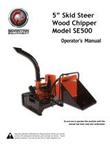
4) Grind the angled edge of the chipping blade at 33 degrees (see below picture) using
a slow wet grinder or have them sharpened by a professional. A bench style grinder
can yield poor results if not used properly. If sharpened to quickly or aggressively on
a bench grinder, the blade edge can get hot and begin to change colour. This
indicates overheating and will remove the heat treat properties of the blade. Use
short grinding times and cool with water. Remove an equal and consistent amount of
material from each blade to maintain proper balance.
Chipper Blade
5) Re-install the sharpened blades on the flywheel and torque the bolts to 40-45 ft-lbs
(54-60N-m).
SETTING BED PLATE GAP
The bed plate (also known as the “anvil plate”) is located at the flywheel housing on the left
side of the infeed chute (when standing at the back of the chipper). The gap between it and
the chipping blades should be set to 1/16”-1/8” (1.5mm-3.0mm). Follow the below steps to
set the gap properly. Failure to set the proper gap can cause poor chipping performance
and/or clogging.
1) If installed, the PTO shaft should be disconnected from the tractor for safety.
2) The upper flywheel housing can be opened to access the blades by using a 24mm
wrench to remove the bolt holding the two halves together.!
Page of 19 34
33°
/