Page is loading ...

Owner’s Manual
ASSEMBLY, CARE & SAFETY INSTRUCTIONS
Item No. HK3797
4 BURNER BBQ
WITH SIDE BURNER
grill roast smoke


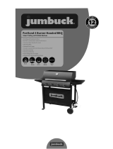
4 Burner BBQ with Side Burner
Warranty Details
The product is guaranteed to be free from defects in workmanship and parts for a period
of 12 months from the date of purchase. Defects that occur within this warranty period,
under normal use and care, will be repaired, replaced or refunded at our discretion. The
benets conferred by this warranty are in addition to all rights and remedies in respect of
the product that the consumer has under the Competition and Consumer Act 2010 and
similar state and territory laws.
Our goods come with guarantees that cannot be excluded under the Australian Consumer
Law. You are entitled to a replacement or refund for a major failure and for compensation
for any other reasonably foreseeable loss or damage. You are also entitled to have the
goods repaired or replaced if the goods fail to be of acceptable quality and the failure does
not amount to a major failure.
After Sales Support
Telephone: 1300 799 787
(03) 9873 2711
Email: [email protected]
YEAR
WARRANTY
grill roast smoke


3
Model No.: HK3797
Product Name: 4 BURNER BBQ WITH SIDE BURNER - For propane (LPG) use only
FOR OUTDOOR USE ONLY. PLEASE READ INSTRUCTIONS CAREFULLY BEFORE
ASSEMBLING. RETAIN THIS MANUAL FOR FUTURE REFERENCE.
FOR YOUR SAFETY
If you smell gas:
1. Shut off gas to the appliance.
2. Extinguish any open ame.
3. Open BBQ hood.
4. If odour continues, immediately call your
gas supplier or your local re department.
PRECAUTIONS
1. Leak test all connections after each tank rell.
2. Never check for leaks with a match or open
ame.
3. Do not store or use gasoline or other
ammable vapours and liquids in the vicinity
of this appliance.
4. The BBQ must not be installed under or on
any combustible material. Minimum clearance
from any combustible materials of ALL sides
of the BBQ is 600mm and 1000mm overhead.
HAZARDOUS FIRE OR EXPLOSION MAY RESULT
IF INSTRUCTIONS ARE IGNORED.
It is the consumer's responsibility to see that the BBQ is properly
assembled, installed, and taken care of. Failure to follow instructions in
this manual could result in injury and/or property damage.
Dimensions 132(W) 56(D) 118.5(H) cm

4
PART DESCRIPTION
A BBQ BODY AND HOOD
B RIGHT HAND SIDE SHELF WITH BURNER
C LEFT HAND SIDE SHELF
D RIGHT HAND END PANEL
E LEFT HAND END PANEL
F BASE PANEL
G LEFT HAND DOOR
H RIGHT HAND DOOR
I CABINET BACK PANEL
J DRIP TRAY
K WARMING RACK
L CAST IRON GRILL
M CAST IRON HOT PLATE
N CABINET TOP RAIL
O BACK RIGHT HAND LEG
P FRONT RIGHT HAND LEG
Q FRONT LEFT HAND LEG
EXPANDED VIEW
PART LIST
PART DESCRIPTION
R BACK LEFT HAND LEG
S DOOR HANDLE X 2PCS
T SIDE BURNER TRIVET
U CONDIMENT RACK
V GREASE PAN
W GREASE PAN HOLDER
X CONTROL KNOB - SIDE BURNER
Y PAPER TOWEL HOLDER
Z FLAME TAMER X 2PCS
AB SIDE BURNER
AC LEFT HAND DRIP TRAY RAIL
AD RIGHT HAND DRIP TRAY RAIL
AE LOCKING CASTOR X 2PCS
AF CASTOR X 2PCS
AG CABINET SPACER RAIL
AH CABINET DOOR STOP
AI HOSE AND REGULATOR
AI

5
PLEASE NOTE THERE ARE ALSO PRE-ASSEMBLED SCREWS ATTACHED TO PARTS
PLEASE FOLLOW INSTRUCTIONS TO IDENTIFY WHAT SCREWS ARE NEEDED
INSTRUCTIONS FOR YOUR NEW BBQ
Tools needed for assembly
Phillips Head Screwdriver (not included)
Before assembly
Please read all instructions thoroughly before proceeding.
Find a large, clean area in which to assemble your BBQ. Please refer to the parts list and
assembly diagram as necessary.
Ensure any transit protection or packaging is removed.
Do not throw out any packaging until BBQ is fully assembled incase parts are still enclosed.
HARDWARE PACK
1/4" SCREW
M6 WASHERS
5/32" SCREW
M4 WASHERS

6
A. ASSEMBLY OF THE BBQ
STEP 1 ATTACH BBQ LEGS TO RIGHT HAND END PANEL
Parts Required
D Right hand end panel
O Back right hand leg
P Front right hand leg
STEP 2 ATTACH BBQ LEGS TO LEFT HAND END PANEL
Parts Required
E Left hand end panel
Q Front left hand leg
R Back left hand leg
— 3pcs screws are pre-assembled on each leg and they
should be screwed out 2-3mm for assembly.
— Align right hand end panel onto screws and tighten as
per figure 1.
— 3pcs screws are pre-assembled on each leg and they
should be screwed out 2-3mm for assembly.
— Align left hand end panel onto screws and tighten as
per figure 2.
RIGHT HAND END PANEL (D)
BACK RIGHT HAND LEG (O)
Figure 1
FRONT RIGHT HAND LEG (P)
Figure 2
BACK LEFT HAND LEG (R)
FRONT LEFT HAND LEG (Q)
LEFT HAND END PANEL (E)

7
STEP 4 FITTING CABINET CASTORS
STEP 3 FITTING CABINET BASE TO LEFT HAND AND RIGHT HAND END
PANEL
Parts Required
AE 2pcs Locking castors
AF 2pcs castors
Parts Required
F Base panel
— Screw locking castors into bottom of left hand legs.
— Screw castors into bottom of right hand legs.
— 8pcs screws are pre-assembled and they should be
screwed out 2-3mm for assembly.
— Once legs are located onto screws, tighten the screws.
This is done through the hole on the legs as per figure 3.
— Please note the hole in the base panel should be
closest to the right hand end panel.
Figure 3
Figure 4
LEFT HAND END PANEL (E)
BASE PANEL (F)
RIGHT HAND END PANEL (D)
HOLE
SCREW LOCKING CASTORS
(AE) IN TO BOTTOM OF
LEFT HAND END LEGS.
SCREW CASTORS (AF)
IN TO RIGHT HAND
END LEGS.

8
STEP 5 FITTING CABINET TOP RAIL
STEP 6 FITTING CABINET BACK PANEL
Parts Required
N Cabinet top rail
Parts Required
I Cabinet back panel
— 4pcs screws are pre-assembled in BBQ legs and they
should be screwed out 2-3mm for assembly as per figure 5.
— Align cabinet top rail on these screws and tighten as per
figure 6.
— 7pcs screws are pre-assembled and they should be
screwed out 2-3mm for assembly.
— Align cabinet back panel onto the screws and tighten as
per figure 7.
Figure 7
Figure 5
Figure 6
CABINET TOP RAIL (N)
CABINET BACK PANEL (I)

9
STEP 7 FITTING CABINET DOOR STOP
Parts Required
AH Cabinet door stop
— By using 2pcs 5/32” screws (from the hardware pack)
screw into threaded holes and tighten as per figure 8.
STEP 8 FITTING DRIP TRAY RAILS
Parts Required
AC Left hand drip tray rail
AD Right hand drip tray rail
— By using 4pcs 5/32” screws (from the hardware pack)
screw into threaded holes and tighten as per figure 9.
Figure 8
Figure 9
CABINET DOOR STOP (AH)
Figure 8
CABINET BACK PANEL (I)
RIGHT HAND DRIP TRAY RAIL (AD)
LEFT HAND DRIP
TRAY RAIL (AC)

10
STEP 9 FITTING DRIP TRAY
Parts Required
J Drip tray
— By using 4pcs 5/32” screws (from the hardware pack)
screw into threaded holes and tighten as per figure 10.
Figure 10
Figure 11 Figure 12
STEP 10 FITTING GREASE PAN HOLDER AND GREASE PAN
Parts Required
W Grease pan holder
V Grease pan
— By using 4pcs 5/32” screws and M4 washers (from the
hardware pack) align the grease pan holder under screw
holes and tighten screws as per figure 11.
— Slide grease pan into holder as per figure 12.
WARNING: GREASE PAN HOLDER MUST ALWAYS BE SECURELY FITTED DURING USE
DRIP TRAY (J)
GREASE PAN (V)
GREASE PAN
HOLDER (W)
GREASE PAN HOLDER (W)

11
STEP 11 FITTING CABINET SPACER RAIL
Parts Required
AG Cabinet spacer rail
— By using 2pcs 5/32” screws (from the hardware pack)
align the cabinet spacer rail over threaded holes and tighten
screws as per figure 13.
Figure 13
CABINET SPACER
RAIL (AG)
STEP 12 FITTING CABINET DOOR HANDLES
Parts Required
S 2pcs Cabinet door handle
G Left hand door
H Right hand door
— By using 2pcs 5/32” screws that are preassembled on
the handle, align handle on the left door face over holes and
tighten screws as per figure 14.
— Repeat the process for the right door.
Figure 14
DOOR HANDLES (S)
LEFT HAND DOOR (G)
RIGHT HAND DOOR (H)

12
STEP 13 FITTING CABINET DOORS
— Locate the bottom fixed pin for each door. Insert the pin into the hole at the corners of the
cabinet base.
— Depress spring pivot in top of each door and locate into the hole in the cabinet top rail as per
figure 15.
Figure 15
STEP 14 FITTING BBQ BODY AND HOOD
Parts Required
A BBQ Body and Hood
— Lower onto cabinet. Place between the tabs on the
back cabinet legs and the tabs on the front of the left and
right hand side panels as per figure 16.
— By using 4pcs ¼” screws (from the hardware pack) screw through the holes in the tabs and
tighten as per figure 17.
Figure 17
SPRING PIVOT
FIXED PIN
Figure 16
Note - Ensure Hose
and Regulator are free
from the underside of
the BBQ Body.
BBQ BODY AND HOOD (A)
LEG TABS
SIDE PANEL TABS

13
STEP 15 FITTING RIGHT HAND SIDE SHELF WITH BURNER
Parts Required
B Right hand side shelf
with burner
— 2pcs screws are pre-assembled on BBQ body and they
should be screwed out 2-3mm for assembly as per figure 18.
— Slide side burner table onto these screws but do not
tighten at this stage.
— Fix the shelf from the inside of the BBQ body with 3pcs ¼" screw and 3pcs M6 washers
(from the hardware pack) as per figure 19.
— Fix front of shelf to BBQ body with 2pcs 5/32” screws and 2pcs M4 washers (from the
hardware pack) as per figure 20. Tighten all screws.
Figure 18
Figure 19
LOOSEN 2PCS PRE ASSEMBLED
SCREWS ON BBQ BODY (A)
View from under side Right Hand Shelf with Burner (B)
3 X ¼" SCREWS AND
M6 WASHERS
RIGHT HAND SIDE SHELF
WITH BURNER (B)
Figure 20
2PCS 5/32" SCREWS AND M4 WASHERS
FROM HARDWARE PACK TO FIX FRONT
PANEL OF SIDE BURNER TO FRONT
PANEL ON BBQ BODY AND HOOD (A)

14
STEP 16 FITTING SIDE BURNER GAS ON/OFF VALVE
— Locate the ON/OFF valve connected to the hose and regulator.
— Fit the valve through the hole in the front of the shelf.
— Attach with 2pcs (pre-assembled) screws as per figure 21.
— Fit control knob (in line with the grooves) to the valve spindle as per figure 22.
VALVE SPINDLE
CONTROL KNOB (X)
Figure 21
Figure 22

15
STEP 17 FITTING SIDE BURNER
Parts Required
AB Side Burner
— Insert side burner (AB) into burner cavity as per figure 23.
— Attach the side burner (AB) onto the control inlet as per
figure 24.
— Fix the burner in place by using 2pcs 5/32” (pre-assembled) screws as per figure 25.
— Connect the igniter wire to the terminal on the back of the valve as per figure 26.
Figure 23
Figure 24
Figure 25
Figure 26
IGNITER WIRE
TERMINAL
SIDE BURNER
BURNER
CONTROL INLET

16
STEP 18 FITTING LEFT HAND SIDE SHELF
Parts Required
C Left hand side shelf
— Slide shelf onto 2pcs (pre-assembled) screws located
on BBQ body as per figure 27.
— Screws should be screwed out 2-3mm when
assembling and do not tighten at this stage.
— Fix the shelf from the inside of the BBQ with 3pcs ¼" screw and 3pcs M6 washers (from the
hardware pack) as per figure 28.
— Fix front of shelf to BBQ body with 2pcs 5/32” screws and 2pcs M4 washers (from the
hardware pack) as per figure 29. Tighten all screws.
Figure 28
View from under side Left Hand Side Shelf (C)
Figure 29
Figure 27
LOOSEN 2PCS 1/4" SCREWS
AND ATTACH SIDE SHELF
BBQ BODY AND HOOD (A)
FIX WITH 2PCS 5/32”
SCREWS AND 2PCS
M4 WASHERS
FIX WITH 3PCS ¼”
SCREWS AND M6 3PCS
WASHERS

17
STEP 19 FITTING FLAME TAMERS
STEP 20 FITTING CAST IRON GRILLS AND HOT PLATE
Parts Required
Z 2pcs Flame tamers
Parts Required
L Cast iron grill
M Cast iron hot plate
— Fit 2 flame tamers over burners as per figure 30.
— Place the cast iron grill and hotplate into the BBQ body
as per figure 31.
— Fit the hotplate above the open burners and the grill
above the flame tamers.
Figure 30
FLAME TAMERS (Z)
BURNERS
Figure 31
FIT CAST IRON HOTPLATE (M)
ABOVE OPEN BURNERS
HOT PLATE MUST BE FITTED
CLOSEST TO THE SIDE BURNER.
FIT CAST IRON GRILL (L)
OVER FLAME TAMERS (Z)

18
STEP 21 FITTING WARMING RACK AND SIDE BURNER TRIVET
Parts Required
K Warming rack
T Side burner trivet
— Fit warming rack into holes in BBQ body as per figure 32.
— Fit side burner trivet into holes located in side shelf over
burner as per figure 32.
STEP 22 FITTING PAPER TOWEL HOLDER AND CONDIMENT RACK
Parts Required
Y Paper towel holder
U Condiment rack
— Locate holes on left hand door panel as per figure 33.
— Attach paper towel holder with 2pcs (pre-assembled)
screws to top rail.
— Attach condiment rack by inserting the ends into holes
provided on the bottom rail.
FIX PAPER TOWEL HOLDER (Y)
TO TOP RAIL
FIX CONDIMENT RACK (U) TO BOTTOM RAIL
Figure 33
Figure 32
WARMING RACK (K)
FIT WARMING RACK (K) INTO
HOLES ON THE BBQ BODY
SIDE BURNER TRIVET (T) FITS INTO
RECESS OVER SIDE BURNER (AB)
/