Bradford White 100T-88B-3N User manual

Category
Water heaters & boilers
Type
User manual
238-44219-00G REV 05/07
A Spanish language version of these instructions is available by contacting
the company listed on the rating plate.
La version espanola de estas instrucciones se puede obtener al escribirle
a la fabrica cuyo nombre aparece en la placa de especificaciones.
WHAT TO DO IF YOU SMELL GAS
Do not try to light any appliance.
Do not touch any electrical switch; do not use any
phone in your building.
Immediately call your gas supplier from a neighbor’s
phone. Follow the gas supplier's instructions.
If you cannot reach your gas supplier, call the fire
department.
Installation and service must be performed by a qualified
installer, service agency or the gas supplier.
For your family’s comfort, safety and convenience, we
recommend this water heater be installed and serviced by a
plumbing professional.
GAS-FIRED WATER HEATER
INSTALLATION & OPERATING INSTRUCTION MANUAL
For Flammable Vapor Ignition Resistant System
Equipped Water Heater
FOR YOUR SAFETY
Do not store or use gasoline or other flammable,
combustible, or corrosive vapors and liquids in the
vicinity of this or any other appliance.
WARNING: If the information in these instructions is not
followed exactly, a fire or explosion may result causing
property damage, personal injury or death.
2
CONGRATULATIONS!
You have just purchased one of the finest water heaters on the market
today!
This installation, operation and instruction manual will explain in detail
the installation and maintenance of your new Flammable Vapor Ignition
Resistant Gas Water Heater. We strongly recommend that you contact a
plumbing professional for the installation of this water heater.
We require that you carefully read this manual, as well as the enclosed
warranty, and refer to it when questions arise. If you have any specific
questions concerning your warranty, please consult the plumbing
professional from whom your water heater was purchased. For your
records we recommend that you write the model, serial number and
installation date of your water heater in the maintenance section in the
back of this manual.
This manual should be kept with the water heater.
Special Flammable Vapor Ignition Resistant System:
This water heater is equipped with a Flammable Vapor Ignition Resistant System.
In the event of improper usage or storage of gasoline or other flammable materials
in the location where the water heater is installed, the technology will resist ignition
of the flammable vapors outside the confines of the water heater.
The Flammable Vapor Ignition Resistant System features:
Advanced Flame Arrestor Design.
Re-settable Thermal Switch to prevent burner/pilot operation with
restricted airflow.
Piezo Igniter
Sight Window to observe operation of pilot and burner.
FOR YOUR SAFETY: Activation of the Flammable Vapor Ignition Resistant
System occurs when flammable vapors are drawn into the water heater and are
combusted. If flammable vapors are detected:
Do not try to light any appliance.
Do not touch any electrical switch; Do not use any phone in your building.
Leave the premises and immediately call the fire department from a
neighbor’s phone. Follow the fire department’s instructions.
Once the flammable vapor has been evacuated, contact your plumbing
professional or the manufacturer for further instructions. Replacement of a
Flammable Vapor Ignition Resistant System equipped water heater due to a
flammable vapor shutdown is not covered under the terms of the limited warranty.
3
TABLE OF CONTENTS
page
GENERAL INFORMATION............................................................ 4
INSTALLATION ............................................................................. 6
Locating The Water Heater.................................................... 6
Minimum Clearances.............................................................. 9
Venting..................................................................................... 10
Combustion Air Supply.......................................................... 11
Water Connections................................................................. 13
Gas Connections.................................................................... 16
GENERAL OPERATION................................................................ 17
Lighting and Shutdown Instructions.................................... 18
Thermostat Adjustment ......................................................... 19
Burner Flame Check............................................................... 20
MAINTENANCE............................................................................. 21
INSTALLATION DRAWING FOR POTABLE WATER.................. 24
PARTS LIST DRAWING................................................................ 25
PARTS LIST................................................................................... 26
INSTALLATION INSTRUCTIONS FOR POTABLE WATER AND
SPACE HEATING.......................................................................... 27
NOTES........................................................................................... 28
4
GENERAL INFORMATION
This gas-fired water heater is design certified by CSA International under the
applicable American National Standard, Z21.10.1 or CSA 4.1-(as indicated on
the rating plate), available from CSA International, 8501 East Pleasant Valley
Road, Cleveland, OH U.S.A. 44131-5575.
This water heater must be installed in accordance with local codes. In the
absence of local codes, it must be installed in compliance with the National
Fuel Gas Code (ANSI Z223.1-Latest Edition), or in Canada CAN/CGA B149.1
Natural Gas Installation Code (Latest Edition) or CAN/CGA B149.2 Propane
Installation Code (Latest Edition). The warranty for this water heater is in
effect only when the water heater is installed, adjusted, and operated in
accordance with these Installation and Operating Instructions. The
manufacturer will not be liable for any damage resulting from alteration and/or
failure to comply with these instructions.
This water heater is not design certified for installation in a mobile home.
Such an installation may create a hazardous condition and will nullify the
warranty.
This water heater has been designed and certified for the purpose of heating
potable water. The installation and use of this water heater for any purpose
other than the heating of potable water may cause damage to the water
heater, create a hazardous condition, and nullify the warranty.
Do not use this appliance if any part has been submerged in water.
Immediately call a qualified service technician to inspect the appliance and to
replace any part of the control system and any gas control, which has been
under water. Depending upon the individual circumstances, it may be
necessary to replace the entire water heater.
Do not store or use gasoline or other flammable, combustible, or
corrosive vapors and liquids in the vicinity of this or any other
appliance.
CAUTION
Incorrect operation of this appliance may create a hazard to life and
property and will nullify the warranty.
DANGER
5
General Information continued-
This water heater has been manufactured for operation at altitudes from sea
level to 2000 feet (610m) (unless otherwise specified on the water heater
rating plate). For use of this appliance at an elevation greater than 2000 feet
(610m), contact the dealer or manufacturer listed on the rating plate for
information on any necessary modification. Uncorrected operation of this
appliance may create a hazard to life and property.
Make sure that you check the rating plate and combination gas control on the
water heater to be certain that the type of gas being supplied corresponds
with the marking on the rating plate and combination gas control.
A sacrificial anode is used to extend tank life. The removal of this anode, for
any reason, will nullify the warranty. In areas where water is unusually active,
an odor may occur at the hot water faucet due to a reaction between the
sacrificial anode and the impurities in the water. If this should happen, an
alternative anode may be purchased from the supplier that installed this water
heater. This will minimize the odor while protecting the tank. Additionally, the
water heater should be flushed with appropriate dissolvers to eliminate any
bacteria.
IMPORTANT
Before proceeding, please inspect the water heater and components for
possible damage. DO NOT install any damaged components. If damage
is evident then please contact the supplier where the water heater was
purchased or the manufacturer listed on the rating plate for replacement
parts.
6
INSTALLATION
LOCATING THE WATER HEATER
This water heater MUST NOT be installed in any location where gasoline
or flammable vapors are likely to be present, unless the installation is
such to eliminate the probable ignition of gasoline or flammable vapors.
Water heaters in residential garages must be installed and located, or
protected, to avoid physical damage. For other installations refer to
local codes. In the absence of local codes, the water heater must be
installed in compliance with the National Fuel Gas Code, (ANSI Z223.1-
Latest Edition), or in Canada CAN/CGA B149.1 Natural Gas Installation
Code (Latest Edition) or CAN/CGA B149.2 Propane Installation Code
(Latest Edition).
The location of this water heater is of the utmost importance. Before installing
this water heater read the Installation section of these instructions. After
reading these Installation and Operating Instructions, select a location for the
water heater where the floor is level and is easily accessible to gas and water
supply lines. DO NOT locate the water heater where water lines could be
subjected to freezing temperatures. Make sure the cold water pipes are
not located directly above the gas control so that condensate during
humid weather does not drip on the controls.
This water heater MUST be installed indoors out of the wind and
weather.
To comply with NSF requirements this water heater is to be:
a) Sealed to the floor with sealant, in a smooth and easily cleanable
way, or
b) Installed with an optional leg kit that includes legs and/or extensions
that provide a minimum clearance of 6” beneath the water heater.
WARNING
Water heaters are heat producing appliances. To avoid damage or injury
there shall be no materials stored against the water heater or vent-air
intake system and proper care shall be taken to avoid unnecessary contact
(especially by children) with the water heater and vent-air intake
components. UNDER NO CIRCUMSTANCES SHALL FLAMMABLE
MATERIALS, SUCH AS GASOLINE OR PAINT THINNER BE USED OR
STORED IN THE VICINITY OF THIS WATER HEATER, VENT-AIR
INTAKE SYSTEM OR IN ANY LOCATION FROM WHICH FUMES
COULD REACH THE WATER HEATER OR VENT-AIR INTAKE
SYSTEM.
7
Installation (Locating The Water Heater) continued-
Note: For California installation this water heater must be braced,
anchored, or strapped to avoid falling or moving during an earthquake.
See instructions for correct installation procedures. Instructions may be
obtained from California Office of the State Architect, 400 P Street,
Sacramento, CA 95814.
Water heater corrosion and component failure can be caused by the heating
and breakdown of airborne chemical vapors. Examples of some typical
compounds that are potentially corrosive are: spray can propellants, cleaning
solvents, refrigerator and air conditioning refrigerants, swimming pool
chemicals, calcium and sodium chloride, waxes and process chemicals.
These materials are corrosive at very low concentration levels with little or no
odor to reveal their presence. NOTE: DAMAGE TO THE WATER HEATER
CAUSED BY EXPOSURE TO CORROSIVE VAPORS IS NOT COVERED
BY THE WARRANTY. DO NOT OPERATE THE WATER HEATER IF
EXPOSURE HAS OR WILL OCCUR. DO NOT STORE ANY POTENTIALLY
CORROSIVE COMPOUNDS IN THE VICINITY OF THE WATER HEATER.
WARNING
Liquefied petroleum gases/propane gas are heavier than air and will
remain at floor level if there is a leak. Basements, crawl spaces, closets
and areas below ground level will serve as pockets for accumulation of
leaking gas. Before lighting, smell all around the appliance area for gas.
Be sure to smell next to the floor.
IF YOU SMELL GAS:
Do not try to light any appliance.
Do not touch any electric switch; do not use any telephone in your
building.
Immediately call your gas supplier from a neighbor’s telephone. Follow
the gas supplier’s instructions.
If you cannot reach your gas supplier, call the fire department.
DO NOT OPERATE APPLIANCE UNTIL LEAKAGE IS CORRECTED!
8
Installation (Locating The Water Heater) continued-
Proper venting practices must be considered when selecting a location for this
water heater. For exact venting specifications, please consult the Venting
section of these Installation and Operating Instructions.
This water heater must be located in an area where leakage of the tank, water
line connections, or the combination temperature and pressure relief valve will
not result in damage to the area adjacent to the water heater or to lower floors
of the structure. When such locations cannot be avoided, a suitable drain pan
must be installed under the water heater. The drain pan must have a
minimum length and width of at least 4 in. (10.2 cm) greater than the diameter
of the water heater and must not restrict proper combustion air flow to the
water heater. The drain pan, as described above, can be purchased from
your plumbing professional. The drain pan must be piped to an adequate
drain. The piping must be at least 3/4 inch (1.9 cm) in diameter and pitched
for proper drainage.
It is recommended that a minimum clearance of four (4) inches (10.2 cm) be
provided on the side of the water heater for servicing and maintenance of the
combination temperature and pressure relief valve.
WARNING
DO NOT ATTEMPT TO LIGHT ANY GAS APPLIANCE IF YOU ARE NOT
CERTAIN OF THE FOLLOWING:
Liquefied petroleum gases/propane gas and natural gas have an
odorant added by the gas supplier that aids in detection of the gas.
Most people recognize this odor as a “sulfur” or “rotten egg” smell.
Other conditions, such as “odorant fade” can cause the odorant to
diminish in intensity, or “fade”, and not be as readily detectable.
If you have a diminished sense of smell, or are in any way unsure of
the presence of gas, immediately contact your gas supplier from a
neighbor’s telephone.
Gas detectors are available. Contact your gas supplier or plumbing
professional for more information.
9
MINIMUM CLEARANCES
WARNING
Failure to adhere to these installation and operating instructions may
create a hazard to life and property and will nullify the warranty.
This installation shall allow access to the front of the water heater and
adequate clearance shall be provided for servicing and operating this water
heater. The water heater may be installed on either a combustible or non-
combustible floor. If the water heater is to be installed directly on carpeting, it
shall be installed on top of a metal or wood panel (or equivalent) extending
beyond the full width and depth of the appliance by at least three (3) inches
(7.6 cm) in any direction or, if the appliance is to be installed in an alcove or
closet, the entire floor shall be covered by the panel. If the rating plate or
the label on the front of the heater specifies minimum clearances less
than those listed in the below table, the water heater may be installed in
accordance with the minimum clearances listed on the rating plate or
the label on the front of the heater.
If it is necessary to install this water heater in an alcove, use the clearances
listed in Figure 1.
Figure 1
10
VENTING
This water heater has been shipped with a draft diverter for which it was
designed with reference to the horizontal and vertical planes. If removed, the
draft diverter must be replaced in the same position and secured to the jacket
top by the screws with which it was installed.
WARNING
The venting system must be installed properly following all local codes or in
the absence of local codes, the latest edition of the National Fuel Gas Code
(ANSI Z223.1- latest edition), or in Canada, The Natural Gas and Propane
Installation Code (B149.1-00 latest edition). Failure to properly install the
venting system could result in property damage, personal injury, or death.
WARNING
Carefully inspect the venting system of a replacement water heater
installation before connecting to the venting system. All joints in the vent
connector must be securely fastened with screws and fit tightly together.
Inspect the venting system for signs of deterioration (rust and perforation)
and replace any sections that are not in good condition.
The chimney must be lined and in good condition. Check to make sure the
venting system is properly sized for the water heater. If the venting system
was previously sized for another gas appliance that has been removed, the
venting system may now be too large. Refer to the latest edition of the
National Fuel Gas Code (ANSI Z223.1-latest edition), or in Canada, the
Natural Gas and Propane Installation Code (B149.1-00 latest edition) for the
correct sizing of venting systems and common venting with another gas
appliance.
Do not vent this water heater into the venting system of another gas
appliance designed to vent under positive pressure.
The water heater should be installed as close as practical to the venting
system to minimize the vent connector length required. Refer to local codes
for the distance limitations on vent connector lengths.
At the completion of the water heater installation, the burner and venting
system must be checked for proper operation with all other commonly
vented appliances in operation. Check for spillage of flue products around
the outside relief opening of the drafthood after several minutes of
operation. The flame from a match should be drawn into the drafthood. Do
not use the water heater or connected equipment if spillage is detected until
the problem is corrected. Refer to the latest edition of the National Fuel Gas
Code, or in Canada, the Natural Gas and Propane Installation Code for
complete details on the “Procedure to Be Followed to Place Equipment in
Operation”.
11
Venting continued-
This water heater must be connected to a lined masonry chimney or venting
system approved by local codes or ordinances. The vent connector used to
attach the draft diverter outlet to the chimney or approved vent must be of the
same diameter as the draft diverter outlet or larger. For proper venting in
certain installations, a larger vent connector may be needed. Consult venting
tables in ANSI standard (Z223.1-or latest edition), National Fuel Gas Code
and CAN/CGA (B149.1 or B149.2-latest editions) Natural Gas and Propane
Installation Code, or local code officials for proper application for your area.
Combustion Air Supply
Provide adequate air for combustion and ventilation. An insufficient supply of
air will cause recirculation of combustion products resulting in air
contamination that may be hazardous to life. Such a condition often will result
in a yellow, luminous burner flame, causing carboning or sooting of the
combustion chamber, burners and flue tubes with possible damage to the
water heater.
When an exhaust fan is installed in the same room with a heater, sufficient
openings for air must be provided in the walls. Undersized openings will
cause air to be drawn into the room through the chimney, causing
recirculation of combustion products.
WARNING
Liquefied petroleum gases/propane gas are heavier than air and will
remain at floor level if there is a leak. Basements, crawl spaces, closets
and areas below ground level will serve as pockets for accumulation of
leaking gas. Before lighting, smell all around the appliance area for gas.
Be sure to smell next to the floor.
IF YOU SMELL GAS:
Do not try to light any appliance.
Do not touch any electric switch; do not use any telephone in your
building.
Immediately call your gas supplier from a neighbor’s telephone.
Follow the gas supplier’s instructions.
If you cannot reach your gas supplier, call the fire department.
DO NOT OPERATE APPLIANCE UNTIL LEAKAGE IS CORRECTED!
IMPORTANT
The flow of combustion and ventilating air must not be obstructed.
Do not block or in any way restrict jacket air inlet slots located at the
bottom front of the water heater.
12
Combustion Air Supply continued-
Confined Spaces
Confined spaces are spaces defined as having less than 50 ft.
3
of space per
1,000 BTU (1.41m
3
/.29kw) per hour of input.
Unconfined Spaces
In unconfined spaces in buildings, infiltration may be adequate to provide air
for combustion, ventilation and dilution of flue gases. However, in buildings of
tight construction (for example, weather stripping, heavily insulated, caulked,
vapor barrier, etc.), additional air may need to be provided using the methods
described above under CONFINED SPACES: All Air From Outdoors or
SPECIALLY ENGINEERED INSTALLATIONS.
All Air From Inside the Building: The confined space shall be provided with
two permanent openings communicating directly with an additional room(s) of
sufficient volume so that the combined volume of all spaces meets the criteria
for an unconfined space. The total input of all gas utilization equipment
installed in the combined space shall be considered in making this
determination. Each opening shall have a minimum free area of 1 square inch
per 1000 BTU (6.45cm
2
/.29kw) per hour of the total input rating of all gas
utilization equipment in the confined space, but not less than 100 square
inches (645cm
2
). One opening shall be within 12 inches (31cm) of the top
and one within 12 inches (31cm) of the bottom of the enclosure.
All Air From Outdoors: The confined space shall be provided with two
permanent openings, one commencing within 12 inches (31cm) of the top and
one commencing within 12 inches (31cm) from the bottom of the enclosure.
The openings shall communicate directly, or by ducts, with the outdoors or
spaces (crawl or attic) that freely communicate with the outdoors.
1. When directly communicating with the outdoors, each opening shall have
a minimum free area of 1 square inch per 4000 BTU (6.45cm
2
/1.2kw) per
hour of total input rating of all equipment in the enclosure.
2. When communicating with the outdoors through vertical ducts, each
opening shall have a minimum free area of 1 square inch per 4000 BTU
(6.45cm
2
/1.2kw) per hour of total input rating of all equipment in the
enclosure.
3. When communicating with the outdoors through horizontal ducts, each
opening shall have a minimum free area of 1 square inch per 2000 BTU
(6.45cm
2
/.6kw) per hour of total input rating of all equipment in the
enclosure.
4. When ducts are used, they shall be of the same cross-sectional area as
the free area of the openings to which they connect. The minimum
dimension of rectangular air ducts shall be not less than 3 inches (7.5cm)
Specially Engineered Installations
The requirements noted under CONFINED SPACES above shall not
necessarily govern when special engineering, approved by the authority
having jurisdiction, provides an adequate supply of air for combustion,
ventilation, and dilution of flue gases.
13
WATER CONNECTIONS
Note: BEFORE PROCEEDING WITH THE INSTALLATION, CLOSE THE
MAIN WATER SUPPLY VALVE.
After shutting off the main water supply, open a faucet to relieve the water line
pressure to prevent any water from leaking out of the pipes while making the
water connections to the water heater. After the pressure has been relieved,
close the faucet. The COLD water inlet and HOT water outlet are identified on
the top of the water heater. The fittings at the cold water inlet and hot water
outlet are dielectric waterway fittings with 3/4” NPT male thread. Make the
proper plumbing connections between the water heater and the plumbing
system to the house. Install a shut-off valve in the cold water supply line.
If this water heater is installed in a closed water supply system, such as the
one having a back-flow preventer in the cold water supply, provisions shall be
made to control thermal expansion. DO NOT operate this water heater in a
closed system without provisions for controlling thermal expansion. Your
water supplier or local plumbing inspector should be contacted on how to
control this situation
After installation of the water lines, open the main water supply valve and fill
the water heater. While the water heater is filling, open several hot water
faucets to allow air to escape from the water system. When a steady stream
of water flows through the faucets, close them and check all water
connections for possible leaks. NEVER OPERATE THE WATER HEATER
WITHOUT FIRST BEING CERTAIN IT IS FILLED WITH WATER.
WARNING
FAILURE TO INSTALL AND MAINTAIN A NEW, LISTED 3/4” X 3/4”
TEMPERATURE AND PRESSURE RELIEF VALVE WILL RELEASE THE
MANUFACTURER FROM ANY CLAIM, WHICH MIGHT RESULT FROM
EXCESSIVE TEMPERATURE AND PRESSURES.
CAUTION
If sweat fittings are to be use, DO NOT apply heat to the nipples on top of
the water heater. Sweat the tubing to the adapter before fitting the adapter
to the water connections. It is imperative that heat is not applied to the
nipples containing a plastic liner.
14
Installation (Water Connections) continued-
WARNING
For protection against excessive temperatures and pressure, install
temperature and pressure protective equipment required by local codes,
but not less than a combination temperature and pressure relief valve
certified by a nationally recognized testing laboratory that maintains
periodic inspection of production of listed equipment or materials as
meeting the requirements of the Standard for Relief Valves and Automatic
Gas Shutoff Devices for Hot Water Supply Systems, ANSI Z21.22 or the
Standard CAN1-4.4. Temperature and Pressure and the Standard CAN1-
4.4, Temperature, Pressure, Temperature and Pressure Relief Valves and
Vacuum Relief Valves. The combination temperature and pressure relief
valve shall be marked with a maximum set pressure not to exceed the
maximum working pressure of the water heater. The combination
temperature and pressure relief valve shall also have an hourly rated
temperature steam BTU discharge capacity not less than the hourly rating
of the water heater.
Install the combination temperature and pressure relief valve into the
opening provided and marked for this purpose on the water heater.
Note: Some models may already be equipped or supplied with a
combination temperature and pressure relief valve. Verify that the
combination temperature and pressure relief valve complies with local
codes. If the combination temperature and pressure relief valve does not
comply with local codes, replace it with one that does. Follow the
installation instructions above on this page.
Install a discharge line so that water discharged from the combination
temperature and pressure relief valve will exit within six (6) inches (15.2
cm) above, or any distance below the structural floor and cannot contact
any live electrical part. The discharge line is to be installed to allow for
complete drainage of both the combination temperature and pressure
relief valve and the discharge line. The discharge opening must not be
subjected to blockage or freezing. DO NOT thread, plug or cap the
discharge line. It is recommended that a minimum clearance of four (4)
inches (10.2 cm) be provided on the side of the water heater for servicing
and maintenance of the combination temperature and pressure relief
valve.
Do not place a valve between the combination temperature and pressure
relief valve and the tank.
15
Installation (Water Connections) continued-
This water heater can deliver scalding temperature water at any faucet in the
system. Be careful whenever using hot water to avoid scalding injury. Certain
appliances such as dishwashers and automatic clothes washers may require
increased temperature water. By setting the thermostat on this water heater
to obtain the increased temperature water required by these appliances, the
potential for scald injury increases. To protect against injury, you should
install an ASSE approved mixing valve in the water system. This valve will
reduce point of discharge temperature by mixing cold and hot water in branch
supply lines. Such valves are available from the manufacturer of this water
heater or a local
plumbing supplier. Please consult with a plumbing
professional.
  
 
  
  
  
 
 

 
 


WARNING
Hydrogen gas can be produced in an operating water heater that has
not had water drawn from the tank for a long period of time (generally
two weeks or more). Hydrogen gas is extremely flammable. To
prevent the possibility of injury under these conditions, we
recommend the hot water faucet to be open for several minutes at the
kitchen sink before you use any electrical appliance, which is
connected to the hot water system. If hydrogen is present, there will
be an unusual sound such as air escaping through the pipes as hot
water begins to flow. Do not smoke or have open flame near the
faucet at the time it is open.
16
Gas Connections
The gas supply lines must meet all requirements of the National Fuel Gas Code (ANSI
Z223.1-Latest Edition), or in Canada CAN/CGA B149.1 Natural Gas Installation Code
(Latest Edition) or CAN/CGA B149.2 Propane Installation Code (Latest Edition).
The minimum permissible gas supply pressure for the purpose of input adjustment is
one (1.0) inch (0.25 kPa) water column above the operating manifold pressure. See
the rating plate and gas valve for the manifold pressure and gas type. The maximum
permissible gas supply pressure is fourteen (14.0) inches (3.5 kPa) water column for
natural gas and liquefied petroleum gases/propane gas.
1. Connect this water heater only to the type of gas (Natural or Propane gas) as
shown on the rating plate. Use clean black iron pipe or equivalent material
approved by local codes and ordinances. (Dirt and scale from the pipe can enter
the gas valve and cause it to malfunction). The inlet gas line must have a
minimum length of three (3) inches (7.6 cm) drip leg (sediment trap) installed as
close to the water heater’s gas valve as possible. A ground joint union must be
installed as close to the water heater as possible in the gas supply line feeding the
water heater to permit servicing of the water heater. Compounds used on the
threaded joints of the gas piping must be resistant to the action of liquefied
petroleum gases/propane gas. DO NOT apply pipe dope to the gas valve inlet and
make certain that no pipe dope has become lodged in the inlet screen of the gas
valve. Extreme care must be taken to ensure no pipe dope enters the gas valve.
Avoid excessive torque when tightening the gas supply line to the gas valve.
Excessive torque may result in cracking of the gas valve housing and could create
a gas leak. When tightening gas supply line to L.P. control, it is recommended to
hold the inlet body of the control securely with an adequate wrench. The
suggested maximum torque is 31.5 ft. lbs. (4.4 kg-m).
2. This water heater and its gas connection must be leak tested before placing the
water heater in operation. Check for gas leaks with a soap and water solution and
a brush or a commercial leak detector fluid. NEVER USE A MATCH OR OPEN
FLAME FOR TESTING!
3. While checking for leaks care must be taken to prevent solution from
contacting the electrical connections at the control. If electrical connections at the
control become wet, they must be thoroughly dried before attempting to operate
the water heater.
WARNING
The manufacturer of this water heater will not be liable for any damage or injury
caused as a result of a cracked gas inlet as a result of excessive torque.
CAUTION
The water heater and individual shutoff valve must be disconnected from the gas
supply piping system during any pressure testing of the system at test pressures in
excess of 1/2 psi (3.5 kPa). The water heater must be isolated from the gas supply
piping system by closing its manual shutoff valve during any pressure testing of the
gas supply system at test pressures equal to or less than 1/2 psi (3.5 kPa). The
supply line must be capped when not connected to the water heater.
17
GENERAL OPERATION
TO FILL THE WATER HEATER
1. Close the water heater drain valve by turning the knob clockwise
.
2. Open the cold water supply shut-off valve.
3. Open several hot water faucets to allow air to escape from the system.
4. When a steady stream of water flows from the faucets, the water heater is
filled. Close the faucets and check for water leaks at the water heater
drain valve, combination temperature and pressure relief valve and the
hot and cold water connections.
TO DRAIN THE WATER HEATER
Should it become necessary to completely drain the water heater, make sure
you follow the steps below:
1. Rotate the thermostat dial clockwise
to the lowest possible position.
2. Rotate and partially depress gas control knob clockwise
to the “OFF”
position.
3. Shut off the gas supply to the water heater.
4. Close the cold water supply shut-off valve.
5. Open the drain valve on the water heater by turning the knob counter-
clockwise
. The drain valve has threads on the end that will allow
the connection of a standard hose coupling.
6. Open a hot water faucet to allow air to enter the system.
To refill the water heater, refer to “To Fill the Water Heater.”
WARNING
Water heaters are heat producing appliances. To avoid damage or injury
there shall be no materials stored against the water heater or vent-air intake
system, and proper care shall be taken to avoid unnecessary contact
(especially by children) with the water heater and vent-air intake system.
UNDER NO CIRCUMSTANCES SHALL FLAMMABLE MATERIALS,
SUCH AS GASOLINE OR PAINT THINNER BE USED OR STORED IN
THE VICINITY OF THIS WATER HEATER, VENT-AIR INTAKE SYSTEM
OR IN ANY LOCATION FROM WHICH FUMES COULD REACH THE
WATER HEATER OR VENT-AIR INTAKE SYSTEM.
18
Lighting and Shutdown Instructions
not open the inner door and attempt to light the pilot by hand.
any gas control which has been under water.
service technician to inspect the appliance and to replace any part of the control system and
D. Do not use this appliance if any part has been under water. Immediately call a qualified
attempted repair may result in a fire or explosion.
not push in or turn by hand, don't try to repair it, call a qualified service technician. Force or
C. Use only your hand to push in or turn the gas control knob. Never use tools. If the knob will
* If you cannot reach your gas supplier, call the fire department.
* Immediately call your gas supplier from a neighbor's phone. Follow the gas supplier's
* Do not touch any electric switch; do not use any phone in your building.
* Do not try to light any appliance.
WHAT TO DO IF YOU SMELL GAS.
to the floor because some gas is heavier than air and will settle on the floor.
B. BEFORE LIGHTING smell all around the appliance area for gas. Be sure to smell next
instructions.
A
. This appliance has a pilot which is lit by a piezo-electric spark gas ignition system. Do
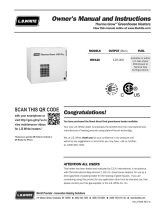
GAS CONTROL
KNOB SHOWN IN
"OFF" POSITION
1. STOP! Read the safety information
above on this label.
2. Set the thermostat to lowest setting.
3. Rotate and if applicable partially depress gas
control knob clockwise to "OFF" position.
NOTE: On exhibit B, knob cannot be
turned from "PILOT" to "OFF" unless knob is
depressed slightly. Do not force.
4. Wait five (5) minutes to clear out any gas.
safety information above on this label.
If you don't smell gas, go to the next step.
Then smell for gas, including near the floor.
If you smell gas, STOP! Follow "B" in the
7. Look into sight
5. Remove outer
on inner door
igniter
button.
to view pilot.
glass window
6. Locate piezo
9a. FOR EXHIBIT A GAS CONTROLS-
Depress and hold down red pilot set button.
Immediately depress piezo igniter button until you
hold down the pilot set button for about one (1)
minute after the pilot is lit. Release the pilot set
button and it should pop back up. Pilot should
remain lit. If it goes out, repeat steps 3 through 9.
9b. FOR EXHIBIT B GAS CONTROLS-
Depress and hold down gas control knob.
Immediately depress piezo igniter button until you
hold down the knob for about one (1) minute
after the pilot is lit. Release the knob and it
should pop back up. Pilot should remain lit. If it
goes out, repeat steps 3 through 9.
FOR EXHIBIT A & B GAS CONTROLS-
If button or knob does not pop up when
released, stop and immediately call your
service technician or gas supplier.
If the pilot will not stay lit after several tries,
turn the gas control knob to "OFF" and call
your technician or gas supplier.
11. Turn gas control knob
10. Replace outer door.
12. Set thermostat to desired setting.
8. Turn the gas control knob counterclockwise
GAS CONTROL
KNOB SHOWN IN
"OFF" POSITION
EXHIBIT A EXHIBIT B
hear a "click" sound, then release. Continue to
1. Set the thermostat dial to lowest possible setting.
2. Rotate and if applicable partially depress gas control knob clockwise to "OFF" position.
causing property damage, personal injury or loss of life.
WARNING: If you do not follow these instructions exactly, a fire or explosion may result
to "PILOT" position.
counterclockwise to "ON" position.
TO TURN OFF GAS TO APPLIANCE
LIGHTING INSTRUCTIONS
TO TURN OFF GAS TO APPLIANCE
FOR YOUR SAFETY READ BEFORE LIGHTING
INNER DOOR
SIGHT GLASS
ELECTRODE
PILOT
BURNER
THERM0-
COUPLE
door.
19
THERMOSTAT ADJUSTMENT
160°F Control 180°F Control
Figure 2
The thermostat dial is set to its lowest temperature setting when shipped from the factory.
Remember that lower temperature settings are more energy efficient. Adjust the
temperature by turning the thermostat dial. It is suggested that the starting point setting not be
greater than the ”
“ or “ “mark on the thermostat dial (approximately 120°F [48.9°C]) as
indicated below. Rotate the thermostat dial clockwise
to decrease the temperature
setting. Rotate the thermostat dial counter-clockwise
to increase the temperature
setting. Adjust the dial until the minimum acceptable temperature is achieved (See figure 2
above for approximate temperature settings).
160°F Control 180°F Control
Figure 3
The thermostat dial is set to its lowest temperature setting when shipped from the factory.
Remember that lower temperature settings are more energy efficient. Adjust the
temperature by turning the thermostat dial. It is suggested that the starting point setting not be
greater than the “
” mark on the thermostat dial (approximately 120°F [48.9°C]) as indicated
below. Rotate the thermostat dial counter-clockwise
to decrease the temperature
setting. Rotate the thermostat dial clockwise
to increase the temperature setting.
Adjust the dial until the minimum acceptable temperature is achieved (See figure 3 above for
approximate temperature settings).
20
General Operation continued-
Hotter water increases the risk of scald injury. Scalding may occur within five (5)
seconds at a temperature setting of 140°F (60
°
C). To protect against hot water
injury, install an ASSE approved mixing valve in the water system. This valve will
reduce point of discharge temperature by mixing cold and hot water in branch
water lines. A licensed plumbing professional or local plumbing authority should
be consulted.
Note: This water heater is equipped with an energy cut out device to prevent
overheating. Should overheating occur or the gas supply fail to shut off, turn
off the manual gas control valve to the appliance and call a qualified service
technician.
Note: Whenever the water heater is filled with cold water, condensate will
form on the cool tank surface and drops of water will fall on the hot burner
and combustion chamber surfaces producing a “sizzling” noise.
Condensation is normal and does not indicate a leak. It will disappear when
the tank becomes heated.
BURNER FLAME CHECKS
Cast Iron Burner: At the time of installation and at periodic intervals (not
more than 6 months), a visual check of the main burner and pilot flames
should be made to determine if they are burning properly. For ideal operation,
the gas and air must be properly proportioned. The proper air-gas mixture is
obtained by adjusting the air shutter on the mixer face of the main burner (See
Figure 4). To adjust for proper burning, loosen the air shutter nut, rotate
shutter to close the opening in the burner then slowly rotate the shutter until
the yellow tips disappear and the flame becomes blue. Tighten the air shutter
nut. Too much air will cause the flame to lift off the burner ports and create
noisy operation. Too little air will result in soot formation. The main burner
flame should light smoothly from the pilot.
Steel Burner: These models are equipped
with self adjusting air mixture and do not
have an adjustable air shutter (See
Figure 4). At periodic intervals, a visual
check of the main burner and pilot
flames should be made to determine
if they are burning properly. The main
burner flame should light smoothly
from the pilot.
Figure 4
DANGER
  • Page 1 1
  • Page 2 2
  • Page 3 3
  • Page 4 4
  • Page 5 5
  • Page 6 6
  • Page 7 7
  • Page 8 8
  • Page 9 9
  • Page 10 10
  • Page 11 11
  • Page 12 12
  • Page 13 13
  • Page 14 14
  • Page 15 15
  • Page 16 16
  • Page 17 17
  • Page 18 18
  • Page 19 19
  • Page 20 20
  • Page 21 21
  • Page 22 22
  • Page 23 23
  • Page 24 24
  • Page 25 25
  • Page 26 26
  • Page 27 27
  • Page 28 28

Bradford White 100T-88B-3N User manual

Category
Water heaters & boilers
Type
User manual

Ask a question and I''ll find the answer in the document

Finding information in a document is now easier with AI