Page is loading ...

Rev04 16-03-2020
Victron Energy B.V. / De Paal 35 / 1351 JG ALMERE / Nederland
Telefoon: (+31) (0)36 535 97 00 / www.victronenergy.com / e-mail: sales@victronenergy.com
Smart BatteryProtect 48/100
ENGLISH
Installation
1. The Smart BatteryProtect (SBP) must be installed in a well-ventilated area and preferably close (max 50
cm) to the battery (but, due to possible corrosive gasses not above the battery!). Voltage drop over a long
or undersized cable between the battery plus and the SBP may result in a short circuit alarm when
starting-up the load, or unexpected shutdown.
2. A properly sized fuse must be inserted according to local regulations in the cable between the battery
and the SBP.
3. The SBP is designed to allow current to flow from IN (battery) to OUT (load) terminals only.
Reverse currents from OUT to IN terminals are strictly forbidden, and
will damage the device. If you wish to use the SBP as a disconnection
for a charge source, you must orient the unit in the system so that the
current is flowing in the intended direction, IN to OUT.
4. The short circuit protection of the SBP will be activated if you try to
directly connect loads with capacitors on their input (eg inverters). For
that use case, please use the SBP to control the remote on/off switch
on the inverter, instead of disconnecting the higher power DC line.
5. Use a 1,5mm² wire (included) for the GND connection, which should
be connected directly to the battery negative terminal (or the chassis of
a vehicle). No other equipment should be connected to this wire.
6. The SBP automatically detects the system voltage once only during
initial power up. During the voltage detection the 7 segment display shows a series of flashes between the
top and lower part.
7. Do not connect the load output until the SBP has been fully programmed.
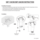
8. A remote on-off switch can be connected between Remote H and Remote L (see figure 1).
Alternatively, terminal H can be switched high (to battery positive), or terminal L can be switched low (to
battery negative).
9. A buzzer, LED or relay can be connected between the alarm output terminal and the battery positive (see
figure 1). Maximum load on the alarm output: 50 mA (short circuit proof).
Load disconnect events and alarm output options
Buzzer or LED mode (buzzer or LED connected to the alarm output):
• In case of under voltage, a continuous alarm will start after 12 seconds. The SBP will disconnect the
load after 90 seconds and the alarm will stop. Reconnect delay: 30 seconds.
• In case of over voltage, the load will be disconnected immediately and an intermittent alarm will
remain on until the overvoltage problem has been corrected. There is no reconnect delay.
Relay mode (relay connected to the alarm output):
• In case of under voltage, the relay will engage after 12 seconds. The SBP will disconnect the load
after 90 seconds and the relay will disengage.
• In case of over voltage, the load will be disconnected immediately and the alarm output will remain
inactive. Overvoltage trip level: 65.2V
Li-ion mode:
• Connect the load disconnect output of the VE.Bus BMS to Remote H terminal.
The load is disconnected immediately when the load-disconnect output of the VE.Bus BMS switches
from ‘high’ to ‘free floating’ (due to battery cell under voltage, over voltage or over temperature). The
under voltage thresholds and alarm output of the SBP are inactive in this mode.
Operation
There are 9 possible error modes and 2 warning modes, indicated by the 7 segment display and within
VictronConnect when using a Bluetooth enabled smartphone or tablet:
• Calibration failure
• Short circuit
• Over temperature / P2 Over temperature warning
• Under voltage / P3 Under voltage warning
• Over voltage
• Configuration Failure
• Reference Voltage Failure
• BMS Lockout
• Reverse current
After 5 minutes the error is no longer displayed to reduce current consumption.
Please refer to the Appendix for more info on each error.
The decimal point of the 7 segment display is used for status indication:
• On solid: the SBP attempts to activate the output
• Flash every 5s: output is active
• Flashing every 2s in Li-ion mode: output ‘connecting’
Remote control and short circuit
• The SBP will connect the load 1 second after closing the remote contact.
• The SBP will disconnect the load immediately when the remote contact is opened.
• When in Li-ion mode the SBP will observe a dead period of 30 seconds after the remote input of the
SBP has become free floating. See the note under figure 4 for a detailed description.
• In case of a short circuit, the SBP will attempt to connect the load every 5 seconds. After two attempts
the display will show (short circuit detected).
Programming
When switched off (remote open), the SBP can be programmed by connecting the PROG pin to ground.
Alternatively, it can be programmed with a Bluetooth enabled smartphone or tablet using VictronConnect
The 7-segment display will first step through the shutdown and restart voltages. Disconnect the PROG pin
when the desired voltage is displayed.
The display will confirm the chosen voltage and default mode (
) twice.
Reconnect the PROG pin to ground if another mode is (
or ) is required. Disconnect when the required
mode is displayed.
The display will confirm the chosen voltage and mode twice.
Bluetooth can be disabled/re-enabled with the VictronConnect app or by connecting the PROG pin to
ground and selecting
(enable) or (disable). See table below
Programming table
7 segment display
Under voltage shut down
48V system
Under voltage restart
48V system
42V
48V
40V
46V
38V
46V
45V
53V
46V
55.2V
42V
51.2V
46V
51.2V
47.2V
51.2V
48V
52V
40V
52.8V
User defined settings with Bluetooth
Buzzer or LED mode
Relay mode
Li-ion mode
Bluetooth Enable
Bluetooth Disable
Specifications
Smart BatteryProtect SBP 48|100
Maximum cont. load current
100A
Peak current
250A
Operating voltage range
24 – 70V
Current consumption
BLE on When on: 1,9mA When off or low voltage shutdown: 1,7mA
BLE off When on: 1,7mA When off or low voltage shutdown: 1,6mA
Alarm output delay
12 seconds
Max. load on alarm output
50mA (short circuit proof)
Load disconnect delay
90 seconds (immediate if triggered by the VE.Bus BMS)
Default thresholds
Disengage: 42V Engage: 48V
Operating temperature range
Full load: -40°C to +40°C (up to 60% of nominal load at 50°C)
Connection
M8
Weight
0,8kg 1.8 lbs
Dimensions (hxwxd)
62 x 123 x 120 mm
2.5 x 4.9 x 4.8 inch
Example Wiring Diagrams
OUT
OUT
IN
IN

Rev04 16-03-2020
Victron Energy B.V. / De Paal 35 / 1351 JG ALMERE / Nederland
Telefoon: (+31) (0)36 535 97 00 / www.victronenergy.com / e-mail: sales@victronenergy.com
Figure 1 Connection diagram of the SBP 48|100
(use the remote input for system on/off functionality)
Connector pin numbering
Figure 2: Connection diagrams and pin numbering
Figure 3: System with 48V Li-ion battery set
(applicable with VE.Bus BMS or miniBMS)
(Remote H terminal, can be connected to battery plus to turn on)
(Remote L terminal, can be connected to battery minus to turn on)
Note: When in Li-ion mode, the SBP will disengage when the H input becomes free floating, and will remain disengaged for 30 seconds even if it
receives a re-engage signal within that time period. After 30 seconds it will respond immediately to a re-engage signal. Therefore, there will
normally be no waiting time if the SBP is used as a system on-off switch (use the System on/off switch in the positive supply of the BMS for this
purpose).
Similarly, if a system shut down occurred due to low cell voltage, the SBP will remain disengaged for 30 seconds even if it receives a re-engage
signal within that time period (which will happen when no other loads are connected to the battery). After 3 attempts to re-engage, the SBP will
remain disengaged until battery voltage has increased to more than 52V during at least 30 seconds (which is a sign that the battery is being
recharged). The under voltage thresholds and alarm output of the SBP are inactive in this mode.
To manually make it start again, briefly disconnect and reconnect the remote on/off terminal or switch the BMS off and on again.

Rev04 16-03-2020
Victron Energy B.V. / De Paal 35 / 1351 JG ALMERE / Nederland
Telefoon: (+31) (0)36 535 97 00 / www.victronenergy.com / e-mail: sales@victronenergy.com
Figure 4: DC solar system with Lithium battery (applicable with VE.Bus BMS or miniBMS)
Caution: uncontrolled reverse current will flow through a Smart BatteryProtect if Vout > Vin. Therefore, never use a Smart BatteryProtect for
battery to battery charging.

Rev04 16-03-2020
Victron Energy B.V. / De Paal 35 / 1351 JG ALMERE / Nederland
Telefoon: (+31) (0)36 535 97 00 / www.victronenergy.com / e-mail: sales@victronenergy.com
APPENDIX
Error/ Warning Codes
E0: Calibration failure
Internal malfunction – calibration data failure/missing
Contact dealer for support – Fault is not user correctable and SBP requires replacement
E1: Short circuit
Short circuit protection is activated in the event of a short circuit, an overload condition or excessive inrush current - such as when attempting to directly power an inverter
1. Check for a potential short circuit condition
2. Confirm that the load current draw does not exceed the SBP current rating
3. Use the SBP to control the remote on/off switch on loads with high inrush currents, rather than directly powering/disconnecting the DC supply
4. Check for loose/high resistance connections and ensure that appropriate gauge wiring is used in the installation
P2: Over temperature warning
Urgent intervention required to prevent load disconnection
Internal temperature close to the limit. Over temperature protection will be activated if temperature continues to rise
E2: Over temperature
Over temperature protection is activated in the event of excessive internal temperature
1. Confirm that the load current draw does not exceed the SBP current rating
2. Check for loose/high resistance connections and ensure that appropriate gauge wiring is used in the installation
3. Do not install the SBP unit in a location exposed to high temperature or radiant heat - relocate SBP to a cooler position or provide additional active cooling
P3: Under voltage warning
Urgent intervention required to prevent load disconnection
Under voltage protection will be activated in 90 seconds if no action is taken
E3: Under voltage
Under voltage protection is activated in the event that the input voltage drops below the under voltage limit selected for 90 seconds
1. Switch off/disconnect loads and recharge the battery
2. Check charging system and battery for proper operation
E4: Over voltage
Over voltage protection is activated in the event that the input voltage exceeds 64V
1. Confirm the configuration of all charging devices in the system - particularly system voltage and charge voltage settings
2. Check charging system for proper operation
3. Confirm SBP system voltage configuration is correct
E5: Configuration failure
Internal malfunction - configuration data failure/missing
To recover the SBP from this condition;
1. Reset the unit to factory defaults under - Settings > More options > Reset to defaults
2. Disconnect all power and wait 3 minutes before reconnecting
3. Reconfigure the unit as required
E6: Reference voltage failure
Internal malfunction - reference voltage failure/missing
Contact dealer for support - Fault is not user correctable and SBP requires replacement
E7: BMS lockout
BMS lockout protection is activated in the event the external BMS requests the SBP to consecutively disengage and then re-engage 3 times (typical behaviour during a shut down due to low cell
voltage)
Once E7 is activated the SBP will remain disengaged until input voltage exceeds 52V
1. Check BMS error codes/log to identify the cause of shut-down and rectify issue
2. Switch off/disconnect loads and recharge the battery
3. Check wiring between BMS and SBP Remote terminal
4. Check BMS for proper operation
E8: Reverse current
Reverse current protection is activated in the event that reverse current flow is detected
CAUTION: SBP is designed to allow or prevent current flow from IN to OUT terminals ONLY. Reverse current flow is strictly forbidden and may permanently damage the SBP.
1. Check that the SBP installation orientation is correct - current flow must be from IN to OUT (refer to example wiring diagrams)
2. Confirm that no charging sources are inadvertently connected to the SBP OUT terminal/circuit
3. If the SBP is used to disconnect a charge source, confirm that no loads are inadvertently connected to the SBP IN terminal/circuit

Rev04 16-03-2020
Victron Energy B.V. / De Paal 35 / 1351 JG ALMERE / Nederland
Telefoon: (+31) (0)36 535 97 00 / www.victronenergy.com / e-mail: sales@victronenergy.com
Figura 4: Sistema solar CC con batería de litio (aplicable con VE.Bus BMS o miniBMS)
Precaución: fluirá una corriente inversa no controlada a través del Smart BatteryProtect si Vout > Vin. Por lo tanto, nunca utilice un Smart
BatteryProtect para cargar de batería a batería.

Victron Energy B.V. / De Paal 35 / 1351 JG ALMERE / The Netherlands
Phone: (+31) (0)36 535 97 00 / www.victronenergy.com / e-mail: [email protected]
/