Page is loading ...

LFLM496-HTK
Hot Water Tank Capacity Extender
Technical Instructions
IS-P-LFLM496-HTK
!
Read this Manual BEFORE using this equipment.
Failure to read and follow all safety and use infor-
mation can result in death, serious personal injury,
property damage, or damage to the equipment.
Keep this Manual for future reference.
WARNING
Need for Periodic Inspection/Maintenance: This prod-
uct must be tested periodically in compliance with local
codes, but at least once per year or more as service con-
ditions warrant. All products must be retested once main-
tenance has been performed. Corrosive water conditions,
inlet temperatures over 200°F (93°C), and/or unauthorized
adjustments or repair could render the product ineffective
for the service intended. Regular checking and cleaning
of the product’s internal components helps assure maxi-
mum life and proper product function.
WARNING
!
Temperature Adjustment 80° to 120°F (27° to 49°C)
Approach Temperature 5°F (3°C) above set point
Maximum Operating Pressure 125psi (861 kPa)
Maximum Hot Water Temperature 200°F (93°C)
Cold Water Temperature Range 39° - 80°F (5° - 27°C)
Maximum Pressure Differential
Between Hot and Cold Supplies 25%
Minimum Flow 0.5gpm (1.90lpm) when
tested in accordance with
ASSE1017 & ASSE 1070
Flow at 45psi pressure drop 13gpm (49lpm)
Listing (valve only) ASSE 1017, ASSE1070 and
IAPMO cUPC
Valve should be installed and adjusted by a licensed contractor
with local codes and ordinances. Further, this valve should be
positioned to allow easy access for cleaning, service andadjust-
ment.
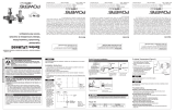
1. Connect hot water side of the valve to the hot water outlet
ofthe hot water tank. Make sure strainer gasket is in place.
2. Install elbow to the mixed outlet of the valve. Make suregas-
ket is in place.
3. Connect tee to the cold inlet of the hot water tank, ensur-
ingthat mixing valve connection is aligned to allow connec-
tion to thecold side of the thermostatic mixing valve with a
corrugated stainless steel connector.
4. Connect female threaded side of the corrugated stainless
steel connector to the cold inlet of the thermostaticmixing
valve and male threaded side to the tee (as shown in Figure 1)
5. Install nipple to the tee and connect cold water inlet supply
to the nipple
6. Connect system hot water outlet supply to the elbow con-
nected to the thermostatic mixing valve outlet.
7. Turn on cold water supply and then hot water supply. Check
for leaks.
8. Adjust temperature to desired setting (see Temperature
Adjustment Section).
Specifiation n
Installation n
Local building or plumbing codes may require modifica-
tions to the information provided. You are required to
consult the local building and plumbing codes prior
to installation. If the information provided here is not
consistent with local building or plumbing codes, the
local codes should be followed. This product must be
installed by a licensed contractor in accordance with
local codes and ordinances.
WARNING
!
+
Thermostatic valve only
+ +
LFLM496-HTK
Thermostatic
Mixing Valve
Elbow
Corrugated
Stainless Steel
Connector
Nipple
Tee
Figure 1

Temperature Adjustment n
Capacity
**
n
Troubleshooting Guide n
1. Make sure hot water tank is turned on and supplying hot
water to the thermostatic mixing valve
2. Turn hot water on at the nearest outlet which is being sup-
pliedby the valve. Let the water run for at least two minutes to
allow supply temperature to stabilize. Make sure to use ther-
mometer to measure the water temperature.
3. See below to adjust the temperature setting of the thermo-
static valve (Figure 2)
IS-P-LFLM496-HTK 1616 EDP#6512336 © 2016 Powers
A Watts Water Technologies Company
Warranty n
The Seller warrants that the equipment manufactured by it and covered by this order or contract is free from defects in material and workmanship and, without
charge, equipment found to be defective in material or workmanship will be repaired, or at Seller’s option replaced F.O.B. original point of shipment, if written
notice of failure is received by Seller within one (1) year after date of shipment (unless specifically noted elsewhere), provided said equipment has been properly
installed, operated in accordance with the Seller’s instructions, and provided such defects are not due to abuse or decomposition by chemical or galvanic action.
THIS EXPRESS WARRANTY IS IN LIEU OF AND EXCLUDES ALL OTHER WARRANTIES, GUARANTEES, OR REPRESENTATIONS, EXPRESS OF IMPLIED. THERE ARE
NO IMPLIED WARRANTIES OF MERCHANTABILITY OR OF FITNESS FOR A PARTICULAR PURPOSE. The Seller assumes no responsibility for repairs made on the
Seller’s equipment unless done by the Seller’s authorized personnel, or by written authority from the Seller. The Seller makes no guarantee with respect to material
not manufactured by it.
WARNING: This product contains chemicals known
to the State of California to cause cancer and birth
defects or other reproductive harm.
For more information: Watts.com/prop65
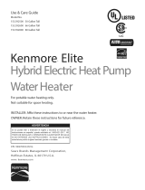
kpa psi
345 50
276 40
207 30
138 20
69 10
0
0 2 4 6 8 10 12 14 gpm
7.6 15 23 30 38 46 53 lpm
Pressure Drop
Hotter
3
/32" Hex Wrench
Turn
Colder
Unscrew, lift
cap to adjust
Symptom Cause Solution
Unable to reach required set point or set
point difficult to set
1. Supply temperatures not within specified limits 1. Check differential temperature between hot and
cold supplies 5°F (3°) required
2. Hot and cold supplies reversed 2. Reinstall valve with supplies to correct connections
3. Filters are blocked by debris 3. Clean filters
Unable to achieve required flow 1. Too much pressure drop at the fixture 1. Measure supply pressures and check against flow
chart. Look for restrictions in valve or piping
2. Check valves /filters blocked by debris 2. Clean check valves/filters
Valve does not maintain required tempera-
ture or temperature changes over time
1. Fluctuation in supply pressure 1. Stabilize water pressures with pressure regulating
or balancing valves
2. Check valves /filters blocked by debris 2. Clean check valves/filters
Discharge temperature too hot or too cold Valve not calibrated properly Readjust valve temperature per installation instruc-
tions
Valve is noisy 1. Water velocity is too high 1. Reduce water velocity with pressure regulating
valve
2. Valve is not sized properly 2. Check flow required versus rated flow capacity of
the valve
No flow from valve Check valves /filters blocked by debris Clean check valves/filters
Flow from the valve fluctuates 1. Fluctuation in supply pressure 1. Stabilize water pressures with pressure regulating
or balancing valves
2. Check valves /filters blocked by debris 2. Clean check valves/filters
Figure 2
Flow curves are for reference. Actual flows may vary depending on sys-
tem temperatures and/or pressures.
**Flow curve with integral inlet filters and check valves
USA: Tel: (800) 669-5430 • Fax: (847) 229-0526 • PowersControls.com
Canada: Tel: (905) 332-4090 • Fax: (905) 332-7068 • PowersControls.ca
Latin America: (52) 81-1001-8600 • Fax: (52) 81-8000-7091 • PowersControls.com
/