Page is loading ...

INSTRUCTION MANUAL
6810-22
Ultra Cable Feeder
52045207 REV 1 © 2010 Greenlee Textron Inc. 4/10
Serial Code AJW
Read and understand all of the instructions and
safety information in this manual before operating
or servicing this tool.
Register this product at www.greenlee.com

6810-22 Ultra Cable Feeder
Greenlee / A Textron Company 4455 Boeing Dr. • Rockford, IL 61109-2988 USA • 815-397-7070
2
Description
The Greenlee Ultra Cable Feeder is intended to pull
cable off of reels to allow feeding the cable into conduit
or cable tray.
The Ultra Cable Feeder is not intended to pull cable or
rope through conduit.
Safety
Safety is essential in the use and maintenance of
Greenlee tools and equipment. This instruction manual
and any markings on the tool provide information for
avoiding hazards and unsafe practices related to the
use of this tool. Observe all of the safety information
provided.
Purpose of this Manual
This instruction manual is intended to familiarize all
personnel with the safe operation and maintenance
procedures for the Greenlee Ultra Cable Feeder Cable
Feeding System.
Keep this manual available to all personnel.
Replacement manuals are available upon request at no
charge at www.greenlee.com.
Do not discard this product or throw away!
For recycling information, go to www.greenlee.com.
All specications are nominal and may change as design
improvements occur. Greenlee Textron Inc. shall not be liable for
damages resulting from misapplication or misuse of its products.
KEEP THIS MANUAL
Table of Contents
Description .................................................................... 2
Safety ............................................................................ 2
Purpose of this Manual ................................................. 2
Important Safety Information .....................................3–4
Identication .................................................................. 5
Specications ................................................................ 5
Features ......................................................................... 6
Transportation ............................................................... 6
Setup ........................................................................7–10
Positioning the Cable Feeder and Cable Reels ......... 7
Securing the Cable Feeding System ......................... 8
Loading the Cable Feeder ......................................... 9
Loading Cable .......................................................... 10
Operation ..................................................................... 11
Tips for Trouble-free Operation ................................ 11
Troubleshooting ......................................................12–13
Service ....................................................................14–15
Illustrations and Parts Lists ....................................16–25
Wiring Schematic ........................................................ 26

6810-22 Ultra Cable Feeder
Greenlee / A Textron Company 4455 Boeing Dr. • Rockford, IL 61109-2988 USA • 815-397-7070
3
IMPORTANT SAFETY INFORMATION
SAFETY
ALERT
SYMBOL
This symbol is used to call your attention to hazards
or unsafe practices which could result in an injury or
property damage. The signal word, dened below,
indicates the severity of the hazard. The message
after the signal word provides information for pre-
venting or avoiding the hazard.
Immediate hazards which, if not avoided, WILL result
in severe injury or death.
Hazards which, if not avoided, COULD result in
severe injury or death.
Hazards or unsafe practices which, if not avoided,
MAY result in injury or property damage.
Read and understand all of the
instructions and safety information
in this manual before operating or
servicing this tool.
Failure to observe this warning will
result in severe injury or death.

6810-22 Ultra Cable Feeder
Greenlee / A Textron Company 4455 Boeing Dr. • Rockford, IL 61109-2988 USA • 815-397-7070
4
IMPORTANT SAFETY INFORMATION
Do not use the cable feeder in a
hazardous environment. Hazards
include ammable liquids, gases,
or other materials. Using the cable
feeder in a hazardous environment
can result in a re or explosion.
Failure to observe these warnings will
result in severe injury or death.
Crushing hazard:
Keep all parts of the body away •
from the tires.
Do not wear loose clothing when •
operating this tool.
Failure to observe this warning could
result in severe injury or death.
This device contains no brake mech-
anism. Do not use as a cable brake
or to raise or lower loads. A runaway
condition could occur resulting in
severe injury or death.
Disconnect from power when loading cables. •
Accidental start-up can result in serious injury.
Do not attach lifting slings to the upper drive unit. •
The drive unit will break loose and the cable feeder
will fall.
Failure to observe this warning could result in severe
injury or death.
Electric shock hazard:
Inspect the power cord before •
connecting to a power source.
Using a damaged cord can result in
electric shock.
Disconnect tool from power source •
before servicing. Electric shock can
result.
Failure to observe these warnings
could result in severe injury or death.
Do not remove guards.
Failure to observe this warning could
result in severe injury or death.
Do not load with cables totaling more than 150 mm •
(6") across. Cables may feed off of the tires, result-
ing in cable damage.
Do not allow sharp objects to contact the tires. •
Failure to observe this precaution may result in
damage to the tire.
Inspect the tool before using. Replace worn, •
damaged or missing parts with Greenlee replace-
ment parts. A damaged or improperly assem-
bled component could break and strike nearby
personnel.
Use this tool for manufacturer’s intended •
purpose only. Use other than that which is
described in this manual can result in injury or
property damage.
Note: Keep all decals clean and legible, and replace
when necessary.

6810-22 Ultra Cable Feeder
Greenlee / A Textron Company 4455 Boeing Dr. • Rockford, IL 61109-2988 USA • 815-397-7070
5
Identification
Upper drive
unit
Cable divider
Emergency Stop Switch
(see “Operation” section)
Ground separator
Transport
handle
Stiff-arm
receptacle
Tee
Anchor pads
Specifications
Power Supply .................................................................... 230 VAC, 8 amps, 50/60 Hz
Power Output ......................................................................................... 1/2 hp (373 W)
Speed ..................................................... 1.3 m/min to 12 m/min (4 ft/min to 36 ft/min)
Cable Capacity ...........................................................................................152 mm (6")
Maximum Tractive Force
Single Cable ...........................................................................approx. 890 N (200 lb)
All Cables .............................................................................approx. 3560 N (800 lb)
Total Reel Capacity ......................................................... approx. 11,300 kg (25,000 lb)
Mass/Weight ...........................................................................................130 kg (285 lb)
Size .............................................. 1040 mm x 699 mm x 953 mm (41" x 27.5" x 37.5")
Tire Pressure
Carlisle Turf Glide ...............................................................................1.5 bar (22 psi)
Carlisle USA Trail ................................................................................3.8 bar (50 psi)
Upper drive unit
attachment pin
Upper drive unit
Lower drive unit
Lower drive
handle
Ratchet

6810-22 Ultra Cable Feeder
Greenlee / A Textron Company 4455 Boeing Dr. • Rockford, IL 61109-2988 USA • 815-397-7070
6
Features
Wide tire grip accommodates: •
– 8 x 250 MCM cable
– 6 x 500 MCM cable
– 5 x 750 MCM cable
Dividers prevent tangling of cables•
Ground Cable Separator ensures traction on smaller •
diameter cable
Variable speed control to match the speed of most •
cable pullers
Quick Squeeze Adjustment accommodates indi-•
vidual cables from 6.5 mm to 89 mm (1/4" to 3-1/2")
diameter
Top loading or side loading•
Hand-held pendant control switch•
Twin drive traction wheels for optimum pulling power•
Low-speed DC motors provide quiet operation•
Efcient permanent-magnet motor design requires •
little power
Maintenance-free chain drive•
Transportation
To transport the cable feeder, pull the telescoping
handles out until they stop. If transporting over a
smooth surface, lift up on the handles to extend the
retractable caster. Quickly set the feeder down after the
caster swings out. To retract the caster, lift up on the
handles and quickly set the feeder down after the caster
swings back in.
If hoisting, attach slings only to the main frame. Feed
lifting sling all the way through the frame underneath the
front cable guides as shown.
Do not attach lifting slings to the upper drive unit.
The drive unit will break loose and the cable feeder
will fall.
Failure to observe this warning could result in severe
injury or death.
Lifting
sling
Upper Drive Unit
(shaded area)

6810-22 Ultra Cable Feeder
Greenlee / A Textron Company 4455 Boeing Dr. • Rockford, IL 61109-2988 USA • 815-397-7070
7
Setup
Positioning the Cable Feeder
and Cable Reels
Locate the cable feeder and cable reels so that:
the cable can be slack between the cable feeder and •
the conduit or tray.
the cables approach the cable feeder at a maximum •
angle of 25° from centerline.
a reel with smaller ground cable is to the left of the •
other reels.
the cable insulation will not be damaged.•
Note: The cable can feed from the top or the bottom of
the reel.
25° max.
2" conduit
Provide enough
distance for the
cable to be slack
Smaller ground
cable goes on left
25° maximum
from centerline
when cable feeds
from outside edge
of reel
tee

6810-22 Ultra Cable Feeder
Greenlee / A Textron Company 4455 Boeing Dr. • Rockford, IL 61109-2988 USA • 815-397-7070
8
Setup (cont’d)
Securing the Cable Feeding System
Select either the Stiff-Arm Boom method or the Anchor
method to secure the cable feeder.
Stiff-Arm Boom Method
Insert one end of a length of 2" rigid or IMC conduit into
the receptacle on the back of the cable feeder. Slip the
tee (supplied with the cable feeder) over the other end
of the conduit. Slide a second length of 2" rigid or IMC
through the tee. Push the cable feeder and stiff-arm
boom up against the reel stands.
Note: If feeding cable has been removed from the reels,
set the stiff-arm boom against a step, curb, door thresh-
old,
stake driven into ground, etc.
Anchor Method
Use 3/8" - 1/2" anchors (purchased separately) through
the four anchor pads to stabilize the cable feeder.
Stiff-Arm Boom against Reel Stand
2" Rigid
IMC
Cable
Feeder
2" Rigid
IMC
tee
Stiff-Arm Boom against Step

6810-22 Ultra Cable Feeder
Greenlee / A Textron Company 4455 Boeing Dr. • Rockford, IL 61109-2988 USA • 815-397-7070
9
Setup (cont’d)
Loading the Cable Feeder
Select either End Loading method or Side Loading
method. Then proceed to the “Loading Cable” section.
End Loading Method
Pinch points: Grasp the middle of the handle.
Failure to observe this precaution may result in injury.
1. Release the ratchet mechanism by pushing down
on the upper drive handle while rotating the top of
the handle toward you.
2. Lift and pivot the upper drive unit back until it
contacts the stops.
3. Rotate the cable divider out and up.
Side Loading Method
1. Release the ratchet mechanism by pushing down
on the upper drive handle while rotating the top of
the handle toward you.
2. Remove the two clevis pins.
3. Unplug the upper drive unit motor.
The upper drive unit is heavy and requires more than
one person to lift.
Failure to observe this precaution may result in injury.
4. Lift the upper drive unit out of the cable feeder.
5. Remove the cable divider.
Cable divider
Push down
on handle
while rotating.
Push down
on handle
while rotating.

6810-22 Ultra Cable Feeder
Greenlee / A Textron Company 4455 Boeing Dr. • Rockford, IL 61109-2988 USA • 815-397-7070
10
Setup (cont’d)
Loading Cable
1. Rotate the ground separator out and down.
3. Lower or remount the upper drive unit by lifting up
on the catch located near the clevis pin on the
control box side of the unit while lowering the upper
drive unit.
4. Push down on the ratchet handle with a moderate
amount of force. Engage the catches.
5. Rotate the ground separator and cable divider into
place, if desired. If pulling more than ve cables,
place two cables in one section of the cable divider.
Make sure the cable divider is fully seated against
the Stiff-arm Shaft.
Note: If pulling cable larger than 600 volt 1000 MCM,
do not use the cable divider.
2. Feed the cables over the lower traction wheel.
Do not cross the cables. •
If pulling a smaller diameter ground cable, feed it •
in at the leftmost side of the cable feeder.

6810-22 Ultra Cable Feeder
Greenlee / A Textron Company 4455 Boeing Dr. • Rockford, IL 61109-2988 USA • 815-397-7070
11
Operation
1. Be sure the main power switch is OFF.
2. Plug the cable feeder into the power source.
3. Turn the speed control knob to the 10 o’clock or
11 o’clock position.
4. Turn the cable feeder ON by doing one of the
following:
Press the momentary switch on the pendant •
control.
Turn on the main switch.•
5. Rotate the knob on the control box:
clockwise to increase speed•
counterclockwise to decrease speed•
When the pull is nished, turn the main power switch OFF.
Note: You can turn off the cable feeder at any time
by pressing the red emergency stop switch. To reset it,
twist it clockwise.
Emergency
Stop Switch
Tips for Trouble-free Operation
Take up slack between the reels and the cable feeder •
before starting the pull.
Start at a slow setting.•
Switch the cable feeder on and off as little as possible •
during the pull. Use the speed control to match the
puller’s speed.
Use the speed control to prevent the cable between •
the cable feeder and the conduit from becoming taut.
Allow that portion of cable to remain slack.
If pulling a smaller diameter cable, the tires will •
contact it at a larger radius than the other cables.
This may cause the ground cable to feed out faster
than the other cables. To compensate for this, pull the
ground cable back as follows:
(1) Increase the speed until you have built up a
15-second buffer of cable slack.
(2) Loosen the ratchet mechanism and pull back
the extra ground cable.
(3) Tighten the ratchet. Return the feeder to its
previous speed and continue pulling.
If the ground cable slips excessively, place it and the •
next cable between the rst and second bars of the
cable divider. Place the other cables to the right.
If any of the incoming cables approaches the cable •
feeder at too steep an angle, the cable feeder may lift
upward. If this happens, move the feeder away from
the reels, anchor the feeder to the ground, or feed the
cable from underneath the reels.
Keep this
angle to a
minimum.

6810-22 Ultra Cable Feeder
Greenlee / A Textron Company 4455 Boeing Dr. • Rockford, IL 61109-2988 USA • 815-397-7070
12
Troubleshooting
Problem Probable Cause Probable Remedy
Will not run.
Speed control off. Turn speed control clockwise.
E-stop engaged. Twist switch button clockwise to reset.
Cables slip. Too little pinching force. Engage ratchets another notch.
Too little tire pressure. Inate tires to maximum recommended
pressure listed on tire sidewall.
Upper drive unit unplugged. Plug in upper drive unit.
Reel(s) hanging up or dragging.
Inspect cable reels for free unobstructed
operation.
Motor runs, but tire does not turn. Broken chain.
Replace.
Front end of feeder lifts off ground
during operation.
Angle of cable from reels to
feeder is too steep.
Use longer stiff-arm boom to place
feeder further from reel(s) and reduce
angle. Anchor feeder to ground. Feed
cable(s) from under reels.

6810-22 Ultra Cable Feeder
Greenlee / A Textron Company 4455 Boeing Dr. • Rockford, IL 61109-2988 USA • 815-397-7070
13
Troubleshooting (cont’d)
Red and black wires are
reversed at rectier.
Is 230 VAC measured at
rectier input?
(the blue and brown wires)
Disconnect potentiometer
unit from controller. Does
feeder run when turned on?
Replace
potentiometer
unit.
Is approximately 280 VDC
measured at rectier output?
(the red and black wires)
Bad wire or
connection.
Make sure the Emergency
Stop switch is released.
Does unit run by toggle switch but
not by the pendant switch?
Bad pendant or cord.
Replace transformer unit.
Does wire from the “P Sw” terminal
of the transformer unit connect to
the positive terminal of the relay by
way of the E-stop switch?
Polarity to the relay is
backwards.
Replace proportional
controller.
Is 8–16 VDC being supplied from
the “P Sw” and “R–” terminals of
the transformer unit?
Place a jumper wire between the
two larger 230 V output terminals
of the proportional controller.
Does unit run when turned on?
Bad wire or incorrect
wiring.
Replace the relay.
Place a jumper wire between the
two larger 230 V output terminals
of the relay. Does unit run when
plugged in?
No Yes
Yes
No
Yes No
Yes
No
No
No
Yes
Yes
Motor runs backwards. Variable speed does not work. Only one motor runs.
Is upper motor plugged in?
Repair motor. Replace rectier.
Feeder does not run.
Turn up speed control.
Replace
proportional
controller.
No
Yes
Yes
No

6810-22 Ultra Cable Feeder
Greenlee / A Textron Company 4455 Boeing Dr. • Rockford, IL 61109-2988 USA • 815-397-7070
14
Service
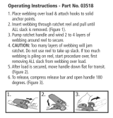
Upper Drive Chain Removal
Pry off the edge guard (26). Remove the 4 screws secur-
ing the chain guard (22) and insert guard (25) that are
in line with the 4 holes in the motor mount arm. Pull the
chain guard out towards the motor mount arm. Slowly
run the feeder until the chain-connecting link is acces-
sible in the space between the tire and the upper motor
guards. Turn off and unplug the feeder. Pry off the con-
necting link C-clip and remove the link. Pull the chain
away from the motor sprocket and remove.
Reassemble in the reverse order noting the following:
The 2 legs of the chain will straddle the single stand off
that is directly between the 2 sprockets. Loosening the
4 bolts that attach the motor may ease tting the
new connecting link. The C-clip should be placed so
the open end faces away from the direction of travel
(counter-clockwise rotation).
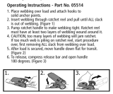
Lower Drive Chain Removal
Remove the 2 screws securing the insert guard (25),
the 5 screws securing the chain guard (22) and the 4
screws securing the lower motor guard (27). Slowly run
the feeder until the chain-connecting link is accessible
in the space between the tire and the frame. Turn off
and unplug the feeder. Pry off the connecting link C-clip
and remove the link.
Reassemble in the reverse order noting the following:
Loosen the 4 bolts that attach the motor and rotate it
clockwise. Temporarily retighten one of the top bolts
until the chain is tted and then rotate the motor back
until the chain is taut. Retighten the motor bolts. The
C-clip should be placed so the open end faces away
from the direction of travel (clockwise rotation).
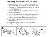
Motor Drive Sprocket Removal
Remove the drive chain. Loosen the 2 set screws that
secure the sprocket. Pull off the sprocket and key.
Reassemble in the reverse order noting the following:
Locate the sprocket with the hub facing outwards and
the inside face of the sprocket about 1/4" from the
upper motor guard or lower motor mounting plate.
Upper Motor Removal
Unplug the upper motor. Remove the upper drive chain.
Remove the 4 bolts attaching the upper motor while
supporting the motor. Remove the motor (28), motor
guard (21), short standoffs (15), second motor guard
(21), long standoffs (20) and the bolts.
Reassemble in the reverse order.
Lower Motor Removal
Remove the lower drive chain. Remove the 4 bolts
attaching the motor (28) and pull out the motor. Remove
the 4 screws attaching the motor electrical box (41) and
pull off the box. Pull off the red and black motor leads
from the rectier. Remove the screw (47), nut (48) and
lock washer (49) securing the ground wires.
Reassemble in the reverse order noting the following:
The lock washer is placed against the electrical box.
Before attaching the electrical box, make sure the motor
is oriented properly. Inserting the motor mount screw
through the frame hole rst will make aligning the 3
other screws easier.
Rectifier Removal
Remove the 4 screws attaching the motor electrical
box (41) and pull off the box. Remove the 4 leads to the
rectier. Remove the screw (61) and nut (62) attaching
the rectier (46).
Reassemble in the reverse order noting the following:
On the upper motor the black wire connects to the
posi-
tive terminal of the rectier and the red wire connects
diagonally opposite. On the lower motor, the red wire
connects to the positive terminal of the rectier and the
black wire diagonally opposite. The positive terminal of
the rectier is the one 90° different that the other 3.
The blue and brown wires are interchangeable on the
remaining 2 terminals.
Control Unit Removal
Unplug the upper motor. Remove the lower motor elec-
trical box as described in rectier removal. Unplug the
blue and brown wires from the rectier and disconnect
the ground wires. Remove the 6 screws securing the
control unit. Pull out the top of the control unit. Remove
the 2 black wires from the emergency stop switch by
loosening the set screws and pulling out the wires.
Remove the control unit.
Reassemble in the reverse order.
(If replacing individual components of the control unit,
pay close attention to the proper wiring shown in the
electrical diagrams, especially the polarity of the low
voltage connections at the relay.)
Main Electrical Box Removal
Remove the control unit. (The wires to the lower motor
can be disconnected at the control unit instead of at
the lower motor to save effort.) Unscrew the nut attach-
ing the exible conduit to the electrical box and pull
the conduit away. Pull out the electrical box while lifting
it up and keeping it square to the frame. Pull off the
contact assembly from the emergency stop switch.
Unscrew the lock nut and remove the switch.
Reassemble in the reverse order.
Upper Traction Wheel Removal
Remove the upper drive unit from the feeder. Remove
the 3 screws that attach the bearing retainer (16) to the
arm (3). Remove the 2 bolts securing the arm to the
cross bar (14). Pull the arm off the axle bearing and
rotate it out of the way. Remove the 4 at head screws
attaching the wheel and lift off the wheel.
Reassemble in the reverse order.

6810-22 Ultra Cable Feeder
Greenlee / A Textron Company 4455 Boeing Dr. • Rockford, IL 61109-2988 USA • 815-397-7070
15
Service (cont’d)
Lower Traction Wheel Removal
Raise or remove the upper drive unit. Remove the 6
screws and nuts attaching the cable guide weldments
(38) to the frame. Loosen but do not remove the 4 at
head screws attaching the traction wheel. Remove the
lower drive chain. Remove the 2 bolts that attach the
traction wheel assembly while supporting the wheel to
prevent thread damage. Remove the wheel assembly.
Remove the 4 at head screws attaching the wheel and
lift off the wheel.
Reassemble in the reverse order noting the following:
Before tightening the 1/2" bolt on the sprocket side of
the feeder, fully assemble all the guards.
Upper Axle Bearing Replacement
Remove the upper drive unit. Remove the 3 screws that
attach the bearing retainer (16) to the arm (3). Remove
the 3 screws that attach the bearing retainer (16) to the
motor mount arm (4). Remove the upper drive chain.
Pull the wheel assembly off the motor mount arm. If
desired, the wheel (1) and chain guard (22) can be
removed. Remove the retaining rings. Press the axle out
of the bearings (34).
Reassemble in the reverse order noting the following:
If the guard carrier weldment (23) and thrust bearing (24)
were removed, they must be reinstalled before the bear-
ings are pressed on. Always use new bearings.
Do not pound or press on the outside of the bearing,
only contact the inner race. In a pinch, an axle spacer
(37) can be used for fully seating the bearings. Before
setting the axle with bearing into the motor mount arm,
make sure the chain guard is correctly oriented towards
the motor; the standoffs will interfere with rotating the
guard into position afterwards.
Lower Axle Bearing Replacement
Remove the lower traction wheel assembly as described
in lower traction wheel removal. Remove the bearing
housing weldment (2) and bearing housing (18). Press
the axle out of the bearings (34).
Reassemble in the reverse order noting the following:
Always use new bearings. Do not pound or press on the
outside of the bearing, only contact the inner race. In a
pinch, an axle spacer (37) can be used for fully seating
the bearings.
Ratchet Weldment Removal
Remove the 2 bolts that attach the right ratchet weld-
ment
(30) and left ratchet weldment (31) to the arm
handle shaft (9).
Reassemble in the reverse order noting the following:
Use the catches on the frame that the ratchet weld-
ments normally latch onto to align the ratchets when
tightening the bolts to assure they are parallel.
Caster Wheel Disassembly
Remove the 2 cotter pins securing the frame shafts
(60) to the frame. Pull out the shafts. Lift up the feeder
and remove the caster wheel assembly from under-
neath. Remove 1 cotter pin from the arm weldment (55)
and remove the lead shaft (58) and the arm weldment.
Remove 1 bolt and washer securing the lead arm weld-
ment (57) and remove the trailing shaft (59) and lead arm
weldment. Remove the 4 nuts and bolts attaching the
caster wheel (54) to the plate weldment (56).
Reassemble in the reverse order noting the following: The
caster wheel (54) mounts on the same side of the plate
weldment (56) as the welded tubes. The arm weldment
(55) attaches to the plate weldment tube closest to the
caster wheel. The lead arm weldment (57) attaches to the
other tube oriented as shown in the parts breakdown. The
lead arm weldment attaches to the inner most set of holes
in the frame.
Commutator Brush Replacement
Remove the motor. Remove the motor electrical box.
Mark a line between the commutator end assembly (28)
and the magnet housing (24) for future alignment. Remove
the 2 nuts (27) securing the commutator end and pull off
the end bell. Note the orientation of the red and black
wires to the brushes. Remove wire strain relief. Remove
the commutator brushes (29 and 30).
Reassemble in the reverse order noting the following:
Orient the brushes as before for proper polarity. The end
of the brush with the wire attached ts into the brush
holder rst with the wire exiting outward. Make sure the
commutator will not contact the brush wires. Hold the
commutator brushes back while the end assembly is
tted over the armature bearing. Make sure your previous
alignment marks are aligned before tightening the nuts
.
Armature Replacement
Remove the commutator end assembly as described in
commutator brush replacement. Remove the magnet
housing. Remove the armature (22).
Reassemble in the reverse order noting the following:
If removed, t the bevil washers so they contact each
other at their inside diameter. Make sure one of the mount-
ing studs passes through the alignment slot between the
magnets when replacing the magnet housing.
Gearbox Disassembly
Remove the armature. Remove the sprocket. Remove
the 4 hex socket cap screws (16). Separate the 2 halves
of the gearbox. Pull out the 1st stage reduction (15). Pull
out the 2nd stage reduction (17). Press out the output
shaft assembly (7). Remove the snap ring (12). Drive out
the ball bearing (13). Use a blind hole bearing puller to
remove any defective needle bearings (4, 5 and 14).
Reassemble in the reverse order noting the following:
Replace any needle bearings that have been removed
with new ones.

6810-22 Ultra Cable Feeder
Greenlee / A Textron Company 4455 Boeing Dr. • Rockford, IL 61109-2988 USA • 815-397-7070
16
Illustration—Main
17
32
13
12
11
(11)
(11)
27
57
10
55
60
58
56
(54)
60
59
54
33
29
52
37
4
25
14
30
22
7
2
34
35
6
1
34
18
35
20
21
15
21
8
28
41
(16)
16
5
1
34
16
52
53
3
31
9
24
36
23
7
34
22
51
(38)
50
(50)
40
41
28
8
37
25
19
(38)
(41)
(66)
(5)
26
(65)
(22)
(25)
(22)
(7)
(9)
(28)
(14)
(29)
(60)
(60)
(27)
(58)
(54)
(59)
(53)
(1)
(8)
65
65
66
66
(32)
(66)
(28)
(2)
(7)
88
38
(8)

6810-22 Ultra Cable Feeder
Greenlee / A Textron Company 4455 Boeing Dr. • Rockford, IL 61109-2988 USA • 815-397-7070
17
Illustration—Motor Box
64
40
39
44
43
47
61
42
45
47
61
41
49
48
46
62
63
49
48
62
46
63
41
63

6810-22 Ultra Cable Feeder
Greenlee / A Textron Company 4455 Boeing Dr. • Rockford, IL 61109-2988 USA • 815-397-7070
18
Parts List —Main and Motor Box
Key Part No. Description Qty
1 50055895 Wheel unit, traction ................................................................................... 2
(1) F015972 Screw, 1/2"-20 UNF x 1.00 lg. at head socket ........................................ 8
2 50055909 Bearing housing weldment ....................................................................... 1
(2) 90551141 Screw, 1/2"-20 UNF x 2.50 lg. hex head .................................................. 2
3 50055950 Arm ............................................................................................................ 1
4 50055976 Arm, motor mount ..................................................................................... 1
5 50055992 Upper axle unit .......................................................................................... 1
(5) 90551133 Retaining ring, Waldes Tru-Arc #5100-78 ................................................. 2
6 50056085 Lower axle unit .......................................................................................... 1
7 50056093 Sprocket, 72 tooth .................................................................................... 2
(7) 90551931 Screw, 1/2"-20 UNF x 1.00 lg. button head .............................................. 8
8 50056115 Sprocket, 10 tooth .................................................................................... 2
(8) 90508815 Screw, 1/4"-28 UNF x .25 lg. cup point socket set ................................. 2
9 50056131 Shaft, arm handle ...................................................................................... 1
(9) 90504542 Screw, 3/8"-24 UNF x 1.00 lg. hex head .................................................. 2
10 50056204 Frame weldment ....................................................................................... 1
11 50056395 Shaft, stiff-arm .......................................................................................... 2
(11) 90503023 Hitch pin .................................................................................................... 2
(11) 90507002 Roll pin, 3/16" x 1.50 lg. ............................................................................ 2
12 50056409 Stiff-arm weldment .................................................................................... 1
13 50056450 Tee weldment ............................................................................................ 1
14 50056468 Cross bar, arm ........................................................................................... 1
(14) 90505247 Screw, 5/16"-18 UNC x 1.50 lg. hex head ................................................ 4
15 50056476 Stand-off, short ......................................................................................... 4
16 50056484 Retainer, bearing ....................................................................................... 2
(16) 90551150 Screw, #10-24 UNC x .37 lg. hex head cap .............................................. 6
17 50056492 Divider weldment ...................................................................................... 1
18 50056522 Housing, bearing ....................................................................................... 1
19 50056530 Ground separator weldment ..................................................................... 1
20 50056573 Stand-off, long .......................................................................................... 4
21 50056581 Guard, upper motor .................................................................................. 2
22 50056590 Guard, chain .............................................................................................. 2
(22) 90516559 Screw, #10 x .50 lg. self-tapping hex head ............................................. 10
23 50056603 Guard carrier weldment ............................................................................ 1
24 50056646 Thrust bearing ........................................................................................... 1
25 50056654 Guard, insert ............................................................................................. 2
(25) 90516559 Screw, #10 x .50 lg. self-tapping hex head ............................................... 4
26 50056662 Guard, edge .............................................................................................. 1
27 50056670 Guard, lower motor ................................................................................... 1
(27) 90516559 Screw, #10 x .50 lb. self-tapping hex head ............................................... 4
28 52045210 Motor ......................................................................................................... 2
(28) F010701 Screw, 5/16"-18 UNC x 4.50 hex head cap (top motor) ........................... 4
(28) 90529324 Screw, 5/16"-18 UNC x .75 socket head cap (lower motor) ..................... 4
88 50056816 Key, 3/16" square x 1" lg. ......................................................................... 2
Note: Key numbers in parenthesis denote unshown hardware used to attach items of the same key number.

6810-22 Ultra Cable Feeder
Greenlee / A Textron Company 4455 Boeing Dr. • Rockford, IL 61109-2988 USA • 815-397-7070
19
Parts List—Main and Motor Box (cont’d)
Key Part No. Description Qty
29 50056697 Axle ........................................................................................................... 1
(29) 90503023 Hitch pin .................................................................................................... 2
30 50056700 Right ratchet weldment ............................................................................. 1
31 50056727 Left ratchet weldment ............................................................................... 1
32 50063987 Handle weldment ...................................................................................... 2
(32) 90507002 Roll pin, 3/16" x 1.50 lg. ............................................................................ 2
33 90548396 Wheel ........................................................................................................ 2
34 90551117 Bearing, Fafnir #204PP ............................................................................. 4
35 90551095 Chain, UST #RSD40 Lamda (98 pitches) .................................................. 2
36 90551125 Bearing, plastic ......................................................................................... 1
37 50320262 Spacer, wheel ............................................................................................ 2
38 50056220 Cable guide weldment .............................................................................. 2
(38) 90505220 Screw, 5/16-18 x 3/4" hex head ............................................................... 6
(38) 90506383 Nut, 5/16-18 nut ........................................................................................ 6
39 90551109 Connector, ex conduit ............................................................................. 1
40 50056832 Box, electrical ........................................................................................... 1
41 50056859 Box, motor electrical ................................................................................. 2
(41) 90551150 Screw, #10-24 UNC x .37 lg. hex head cap .............................................. 8
42 90541243 Strain relief ................................................................................................ 1
43 91852145 Elbow, Sealtite .......................................................................................... 1
44 90545494 Conduit, Sealtite ....................................................................................... 1
45 50058070 Cord, motor power .................................................................................... 1
46 91859972 Rectier ..................................................................................................... 2
47 90539559 Screw, #8-32 x 3/8 long button head ....................................................... 2
48 90524349 Nut, #8-32 hex .......................................................................................... 2
49 90516494 Washer, internal tooth lock ........................................................................ 2
50 52045208 Control unit (includes all items on pages 21–23) ...................................... 1
(50) 90516559 Screw, #10 x .50 lg. self-tapping hex head ............................................... 6
51 90550544 Plug ........................................................................................................... 5
52 90550536 Clevis pin, 3/4 dia. x 1.5 long .................................................................... 2
53 50058495 Catch ......................................................................................................... 1
(53) 90550528 Screw, 3/8 dia. x 3/8 long shoulder .......................................................... 1
54 90551273 Wheel, swivel caster ................................................................................. 1
(54) 90505301 Screw, 3/8-16 UNC x 1.00 hex head ........................................................ 4
(54) 90526465 Nut, 3/8-16 UNC hex lock ......................................................................... 4
55 50057871 Arm weldment ........................................................................................... 1
56 50057880 Plate weldment ......................................................................................... 1
57 50057898 Lead arm weldment .................................................................................. 1
Note: Key numbers in parenthesis denote unshown hardware used to attach items of the same key number.

6810-22 Ultra Cable Feeder
Greenlee / A Textron Company 4455 Boeing Dr. • Rockford, IL 61109-2988 USA • 815-397-7070
20
Parts List—Main and Motor Box (cont’d)
Key Part No. Description Qty
58 50057847 Shaft, lead ................................................................................................. 1
(58) 90506553 Pin, 1/8 cotter ........................................................................................... 2
59 50057855 Shaft, trailing ............................................................................................. 1
(59) 90500598 Screw, 1/4-20 UNC x .50 hex head .......................................................... 2
(59) 90521250 Washer, at................................................................................................ 2
60 50057910 Shaft, frame............................................................................................... 2
(60) 90506553 Pin, 1/8 cotter ........................................................................................... 2
61 90524918 Screw, #10-24 x 3/4 round head ............................................................... 2
62 90533453 Nut, #10-24 ............................................................................................... 2
63 91862639 Nut, 1/2" conduit lock ............................................................................... 3
64 50066820 Switch unit, emergency stop .................................................................... 1
65 50062883 Guard, back .............................................................................................. 2
(65) 90516559 Screw, #10 x .50 lg. self-tapping hex head ............................................... 4
66 50013971 Lanyard ..................................................................................................... 2
(66) 90507002 Roll pin, 3/16" x 1.50 lg. ............................................................................ 2
67 50069209 Decal, product name ................................................................................. 1
68 50069217 Decal, Greenlee ID .................................................................................... 1
Not Shown:
90527879 Masterlink, #40 chain ................................................................................ 1
50057766 Decal, warning .......................................................................................... 2
50057782 Decal, E-stop ............................................................................................ 1
Note: Key numbers in parenthesis denote unshown hardware used to attach items of the same key number.
/