
Power Awning Pro
3316554.XXX, 3316518.XXX, 3316519.XXX, 3316520.XXX
Read these instructions carefully. These instructions MUST stay with this product.
Dometic Corporation reserves the right to modify product appearances and specications without notice.
USA
SERVICE OFFICE
Dometic Corporation
1120 North Main Street
Elkhart, IN 46514
SERVICE CENTER &
DEALER LOCATIONS
Visit:
www.Dometic.com
REVISION B
Form No. 3316690.000 5/19
(French 3316691.000_B)
©2019 Dometic Corporation
LaGrange, IN 46761
INTRODUCTION ....................................................................2
IMPORTANT SAFETY INSTRUCTIONS AND DOCUMENT SYMBOLS ........................2
A. Recognize Safety Information. . . . . . . . . . . . . . . . . . . . . . . . . . . . . . . . . . . . . . . . . . . . . . . . . . . . . . 2
B. Understand Signal Words ......................................................... 2
C. Supplemental Directives .......................................................... 2
D. General Safety Messages ........................................................2
GENERAL INFORMATION ............................................................3
A. Receiver Control Range ..........................................................3
INSTALLATION .....................................................................3
A. Installing The Receiver ...........................................................3
B. Programming The Remote Control .................................................. 4
C. Programming The Vibration Sensor (If Applicable) ......................................5
D. Mounting The Vibration Sensor (If Applicable) .........................................6
OPERATION ....................................................................... 7
A. The Function Of The Remote Control ................................................7
B. Adjusting The Vibration Sensor (If Applicable) .........................................7
C. Other Useful Information. . . . . . . . . . . . . . . . . . . . . . . . . . . . . . . . . . . . . . . . . . . . . . . . . . . . . . . . . . 7
INSTALLATION & OPERATING
INSTRUCTIONS

2
INTRODUCTION
The Power Awning Pro system (hereinafter referred to as “unit” or “Product”) is designed and intended for installation in a Rec-
reational Vehicle (hereinafter referred to as “RV”) during or after the RV manufacture.
The Product kit is available for order with various components so while some graphics may show dierent components, they
still illustrate the correct procedure. All components that were not originally ordered can be purchased as an add-on or up-
grade.
Dometic Corporation reserves the right to modify appearances and specications without notice.
IMPORTANT SAFETY INSTRUCTIONS AND DOCUMENT SYMBOLS
This manual has safety information and instructions to help you eliminate or reduce the risk of accidents and injuries.
A. Recognize Safety Information
This is the safety alert symbol. It is used to alert you to potential physical injury hazards. Obey all safety messages that
follow this symbol to avoid possible injury or death.
B. Understand Signal Words
A signal word will identify safety messages and property damage messages, and will indicate the degree or level of hazard
seriousness.
indicates a hazardous situation that, if NOT avoided, could result in death or serious injury.
indicates a hazardous situation that, if NOT avoided, could result in minor or moderate injury.
is used to address practices NOT related to physical injury.
C. Supplemental Directives
Read and follow all safety information and instructions to avoid possible injury or death.
Read and understand these instructions before [installation / use / service / maintenance] of this product.
Incorrect [installation / operation / service / maintenance] of this product can lead to serious injury.
The installation MUST comply with all applicable local or national codes, including the latest edition of the following stan-
dards:
U.S.A.
• ANSI/NFPA70, National Electrical Code (NEC)
• ANSI/NFPA 1192, Recreational Vehicles Code
CANADA
• CSA C22.1, Parts l & ll, Canadian Electrical Code
• CSA Z240 RV Series, Recreational Vehicles
Indicates additional information that is not related to physical injury.
D. General Safety Messages
Failure to obey the following warnings could result in death or serious injury:
• This product MUST be [installed / serviced] by a qualied service technician.
• Do NOT modify this product in any way. Modication can be extremely hazardous.
• IMPACT OR CRUSH HAZARD. This product should be installed in a controlled environment (inside). Do NOT install
product during windy conditions, or when wind is expected. Otherwise, product could move unpredictably, become un-
stable, and could [detach / bend / collapse].
Compatible ONLY with 9100 power awnings and associated hardware.

3
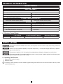
GENERAL INFORMATION
REQUIRED HARDWARE
(1) 3/16" x 1/2" Pop Rivet (optional - installer-supplied)
BASIC COMPONENTS
3316520.201 Wireless Receiver
• Receiver Wire Harness • Dry Contact Switch Wire Harness
• 3316518.201 Remote Control • Miscellaneous Wire Connectors
• Dry Contact Switch (Power)
OPTIONAL COMPONENTS AND KITS
3316519.205 Vibration Sensor (Black) 3316519.202 Vibration Sensor (White)
REQUIRED TOOLS
Drill Phillips Screwdriver / Bit
#11 (0.191") Drill Bit 7/16" Hex Nut Driver / Bit
Riveting Tool Needle Nose Pliers
Flat-Bladed Screwdriver / Bit (Small) Wire Cutter
A. Receiver Control Range
L1 IN THE AIR L2 WITH CONCRETE WALLS EMISSION FREQUENCY
12 V 200 m (656.17 ft) 35 m (114.83 ft) 433.92 MHz
INSTALLATION
ELECTRICAL SHOCK HAZARD. Disconnect 120 Vac power from RV. Failure to obey this warning could result
in death or serious injury.
Install a 15 A fuse (installer supplied) at fuse panel for positive (+) 12 Vdc power supply ( RED wire) to product.
Otherwise, damage to unit could occur.
Disconnect the positive (+) 12 Vdc terminal from supply battery. Otherwise, damage to unit could occur.
Disconnect power for ALL procedures under this section. Use a grommet (installer supplied) or equivalent protec-
tion when routing wire through the RV’s [roof / oor / walls].
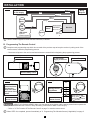
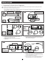
A. Installing The Receiver
1. Determine the receiver location.
2. Route the wiring.
If using dry contact switches, route the installer-supplied wiring inside the RV from the receiver location to the dry contact
switch installation site.

4
INSTALLATION
FIG. 1
Wiring
Diagram
LED Switch
(Optional -
Installer-supplied)
Awning
Motor
15 A Fused
12 VDC Supply
LED
Light
Ignition
Black (-)
Brown (-)
White (-)
On/O Switch
Green-Positive
Black-Extend
Yellow
(not used)
Orange
Red (+)
Blue (+)
Red (+)
Red-Retract
Awning
Switch
Receiver
Use the installer-supplied receiver harness connectors, if desired.
B. Programming The Remote Control
Complete each programming step within four seconds of the previous step to keep the receiver in pairing mode. If the
receiver resets, restart the programming process.
• Disconnect all power to the receiver and wait at least ten seconds before beginning the programming process.
STEP 1
Remove Battery Cover
Back of Remote Control
STEP 2
12 VDC Power
Supply to Receiver
Wireless Receiver
ON
STEP 3
Press the P2
button two times.
The Receiver
beeps once after
each press of the
button.
Back of
Remote Control
x2
x2
STEP 4
Awning Retract
(Up) Button
Front of
Remote Control
x4
x1
IMPACT OR CRUSH HAZARD. Make sure the awning retract button and the awning extend button operate the
awning in the intended direction. Failure to obey this waring could result in death or serious injury.
• Refer to "A. The Function Of The Remote Control" on page 7 to test the remote control.
When STEP 4 is completed, proceed immediately to "C. Programming The Vibration Sensor (If Applicable)" on page 5.
* When used on 9500
awning, press Down
button at Step 4 instead
of Up button.
*

5
INSTALLATION
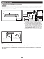
C. Programming The Vibration Sensor (If Applicable)
Complete each programming step within four seconds of the previous step to keep the receiver in pairing mode. If the
receiver resets, restart the programming process.
• When installing a vibration sensor, complete the steps in "B. Programming The Remote Control" on page 4 then
start with STEP 1 of this procedure without delay.
STEP 1
Sensor Base
Vibration Sensor
Battery
Compartment
Front of
Sensor
Back of
Sensor
STEP 2
Sensor Dial
Set to 0
Vibration Sensor
Battery Compartment
STEP 3
Back of
Remote
Control
x1
a.
b.
x1
x1
x2
a. Press the P2 button once. The wireless receiver
beeps once and the awning jogs.
b. Press the P2 button a second time. The receiver
beeps once.
STEP 4
Vibration
Sensor
Battery
Compartment
Programming
Button
x1 x5 x1
x1
a. Press the vibration sensor programming button. The
sensor beeps once, the wireless receiver beeps ve
times, and the awning jogs.
STEP 5
Sensor Dial
Set to 5
Vibration
Sensor Battery
Compartment
STEP 6
Programming
Button
The Awning
retracts.
x1
x1
a. Set the vibration sensor dial to the desired level of
detection (see Operation, "B. Adjusting The Vibration
Sensor (If Applicable)" on page 7).
b. Press the vibration sensor programming button once.
The sensor beeps once, and the awning retracts.

6
INSTALLATION
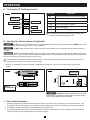
D. Mounting The Vibration Sensor (If Applicable)
IMPACT OR CRUSH HAZARD. This product should be installed in a controlled environment (inside). Do NOT
install product during windy conditions, or when wind is expected. Otherwise, product could move unpredictably, become un-
stable, and could [detach / bend / collapse].
• Fully close the awning.
STEP 1
Sensor Base
Vibration Sensor
STEP 2
Lockwasher
1/4-20 x 3/4"
Screw
Sensor Base
Pop Rivet
Front
Channel
Drill #11 Hole
Top Mounting
Bracket
a. Remove and reuse the screw and lock washer on the
front channel to install the vibration sensor base.
b. If using a secondary securement (installer supplied
pop rivet), open the awning far enough to remove the
top wire cover from the front channel. Remove the
wire cover to the motor wire and pull it out of the way
to avoid damaging the wire. Reconnect after mount-
ing the vibration sensor base.
c. Re-install the vibration sensor onto the sensor base.
STEP 3
Rapidly raise and
lower the roller
tube to activate the
Vibration Sensor.
Awning will
completely close.
Vibration Sensor
No direct correlation exists between the sensitivity settings on this sensor and true wind speed. The vibration sensor will
close the awning any time the motion in the attached hardware arm reaches the pre-set level regardless of the cause of
this motion. Wind speed, angle of attack, and the size of the awning are only a few factors that can aect how an awning
reacts to environmental conditions.
Refer to "B. Adjusting The Vibration Sensor (If Applicable)" on page 7 if the sensor fails to activate or the sensor is too
sensitive.

7
OPERATION
A. The Function Of The Remote Control
STEP 1
Up Button
(not used)
LED +
Down Button
LED −
LED Button
BUTTON FUNCTION
Up Retracts the awning when the button is held
Stop Not used in this application
Down Extends the awning when the button is held
LED Turns LED light(s) on and o
LED − Dims LED light(s)
LED + Brightens LED light(s)
For Motorized RVs Only: Make sure the awning auto-
matically closes when starting the RV.
B. Adjusting The Vibration Sensor (If Applicable)
Do NOT rely on the vibration sensor to prevent damage to the awning. The awning should ALWAYS be closed
when unattended or when strong [rain / wind / etc.] is expected.
Do NOT hang any items from or block the travel of the hardware arms or awning when the vibration sensor is
installed.
IMPACT OR CRUSH HAZARD. Keep your hands, arms, head or torso clear of the awning hardware during peri-
ods of rain, wind, etc. These conditions may cause the vibration sensor to unexpectedly activate and retract the awning. Failure
to obey this warning could result in death or serious injury.
The sensitivity of the vibration sensor can be set from 1 (most sensitive) to 9 (least sensitive). Settings 0 and 5 are for
programing only, and are not active vibration settings.
• Refer to "D. Mounting The Vibration Sensor (If Applicable)" on page 6 to remove the vibration sensor from the front
channel.
STEP 1
Back of Sensor
Battery
Compartment
STEP 2
Sensor Dial
ALWAYS conrm functionality of the vibration
sensor after any changes or adjustments are made. Refer to
step 3 to test vibration sensor operation.
C. Other Useful Information
1. For safety purposes, the vibration sensor sends a signal to the receiver every 60 minutes to conrm functionality. If for
any reason (removal, low battery, etc), that signal is not received after 60 minutes, the awning will retract automatically.
2. The vibration sensor will not function if not attached to the sensor base.
3. To extend the awning, depress the down button until the awning is fully deployed. Then, releasing the down button will
cause the awning to stop, and jog back to the nal use position.
-
 1
1
-
 2
2
-
 3
3
-
 4
4
-
 5
5
-
 6
6
-
 7
7


Dometic 3316554, 3316518, 3316519, 3316520 Operating instructions
- Type
- Operating instructions
- This manual is also suitable for
Ask a question and I''ll find the answer in the document
Finding information in a document is now easier with AI
Related papers
-
Dometic 3316518, 3316519, 3317114, 3317115 Operating instructions
-
Dometic 9500E Power Case/Cassette Awning Operating instructions
-
-
 Oliver Travel Trailers Dometic 9500 Motorized Awning User manual
-
-
-
-
-
-

Other documents
-
 Mandalay 2006 Presidio User manual
-
Lippert Components Solera Smart Arm Installation and Owner's Manual
-
 Solera 715124 Installation guide
-
Carefree Mirage User manual
-
 Tiffin Motorhomes 2015 Allegro Open Road Owner's manual
-
 Tiffin Motorhomes 2015 Allegro Open Road Owner's manual
-
 Tiffin Motorhomes 2015 Allegro Open Road Owner's manual
-
-
Carefree Eclipse User manual
-


