Page is loading ...

Tripp Lite World Headquarters
1111 W. 35th Street, Chicago, IL 60609 USA
(773) 869-1234, www.tripplite.com
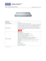
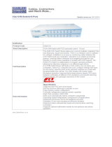
8- or 16-Port 1U Console KVM Switch or
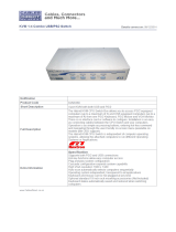
16-Port 1U Rackmount KVM Switch
Model #: B020-008, B020-008-17, B020-016, B020-016-17 or B022-016
NOTE: Follow these instructions and operating procedures to ensure correct performance
and to prevent damage to this unit or to its connected devices.
Copyright © 2007 Tripp Lite. All rights reserved. All trademarks are the property of their respective owners.
The policy of Tripp Lite is one of continuous improvement. Specifications are subject to change without notice.
WARRANTY
REGISTRATION
Register online today for a
chance to win a FREE Tripp Lite
product! www.tripplite.com/warranty
Owner’s Manual
This package should consist of:
• 1 KVM Switch (B020-008, B020-008-17, B020-016, B020-016-17 or B022-016)
• 1 USB Keyboard/Mouse Adapter
• 1 Power Adapter with Power Cord
• Firmware Upgrade Cable
• 1 Owner's Manual with Quick Start Guide
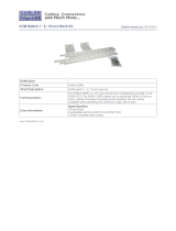
• 1 Rackmount Kit (B022-016 only)
Check to see that the unit arrived undamaged, with all of its contents. Contact your dealer if there is a problem.
200707121 93-2463 KVM Switch Update.qxd 7/31/2007 2:44 PM Page 1

2
Table of Contents
Page
Overview.................................................................................... 3
System Requirements .............................................................. 4
Computers .......................................................................... 4
Console (for B022-016 only) .............................................. 4
Cables ................................................................................ 4
Introduction .......................................................................... 5-7
Front View .......................................................................... 5
B020-008, B020-008-17, B020-016
and B020-016-17 .................................................... 5
B022-016 ................................................................ 6
Rear View .......................................................................... 7
B020-008, B020-008-17, B020-016
and B020-016-17 .................................................... 7
B022-016 ................................................................ 7
Installation ............................................................................ 8-9
Single-Station Installation .................................................. 8
Daisy-Chaining Installation ................................................ 8
LCD OSD (On-Screen Display) Configuration.................. 9
Basic Operation ................................................................ 10-11
Opening the Console ..........................................................10
Closing the Console ..........................................................10
Port Selection ....................................................................10
Hot Plugging .................................................................... 11
Powering Off and Restarting ............................................ 11
Port ID Numbering .......................................................... 11
Port Selection .................................................................... 11
Hotkeys .............................................................................. 12-14
Hotkey Port Control ........................................................ 12
Invoking the Hotkey Mode .............................................. 12
Selecting the Active Port .................................................. 12
Auto Scanning .................................................................. 12
Setting the Scan Interval .................................................. 13
Starting Auto Scan ............................................................ 13
Pausing in Auto Scan ........................................................ 13
Skip Mode ........................................................................ 14
Hotkey Beeper Control .................................................... 14
Hotkey Summary Table .................................................. 14
Page
OSD (On-Screen Display) Operation ............................ 15-20
OSD Overview ................................................................ 15
OSD Navigation .............................................................. 15
OSD Main Screen Headings ............................................ 16
OSD Functions..............................................................16-20
F1 Go To (GOTO) ................................................ 16
F2 List Ports (LIST) .............................................. 16
F3 Set Environment (SET) .................................... 17
F4 Administrator (ADM) ................................ 18-19
F5 Skip (SKP)........................................................ 19
F6 Broadcast Mode (BRC).................................... 19
F7 Scan (SCAN).................................................... 20
F8 Log Out (LOUT) .............................................. 20
Firmware Upgrade Utility................................................ 21-24
Before You Begin.............................................................. 21
Starting the Upgrade ........................................................ 22
Upgrade Succeeded .......................................................... 23
Upgrade Failed ................................................................ 23
Firmware Upgrade Recovery ...................................... 23-24
Appendix A ........................................................................ 24-25
Computer Connection Table ............................................ 24
OSD (On-Screen Display) Factory Default Settings ...... 24
Troubleshooting .............................................................. 25
Specifications .................................................................... 25
Appendix B ............................................................................ 26
Clear Log-in Information .................................................. 26
Appendix C ............................................................................ 27
Standard Rack Mounting .................................................. 27
Optional Rack Mounting .................................................. 28
Appendix D ............................................................................ 28
FCC Radio/TV Interference Notice .................................. 28
Warranty ..........................................................................28
Warranty Registration ........................................................28
200707121 93-2463 KVM Switch Update.qxd 7/31/2007 2:44 PM Page 2

3
Overview
The B020-008, B020-008-17, B020-016, B020-016-17 and B022-016 KVM Switches allow access to
multiple computers from a single console (keyboard, mouse, and monitor).
Features Include:
• Integrated KVM Console on the B020-016 and B020-008 Console KVM—Includes a 15" LCD Monitor,
Keyboard and Touchpad in a 1U Rackmount Housing
• Integrated KVM Console on the B020-016-17 and B020-008-17 Console KVM—Includes a 17" LCD
Monitor, Keyboard and Touchpad in a 1U Rackmount Housing
• Space-Saving Technology—Controls up to 16 Computers (B020-016, B022-016) or 8 Computers (B020-008)
• Daisy-Chain up to 31 more B022-016 KVMs—Control up to 512 Computers From a Single Console
• Modular Design on B020-008, B020-008-17, B020-016 and B020-016-17:
• Console Detaches From the Switch Chassis for Easy Maintenance
• Keyboard/Touchpad Module is Easily Removed for Quick Repair or Replacement—Eliminates
Lengthy Downtime—No Need to Return the Switch to the Factory
• No Software Required—Select Computer via Hotkeys or Mouse Driven On- Screen Display (OSD) Menus
• Auto Scan Feature for Monitoring User—Selected Computers
• Hot Pluggable—Add/Remove Computers Without Powering Down the Switch
• Daisy-Chained Station Position Auto-Sensed—No Need For Manual DIP Switch Setting (Keyboard
LED Indicates Station Position)
• Port Names Automatically Reconfigured When Station Sequence Is Changed
• Two-Level Password Security—Only Authorized Users View and Control the Computers (Up to Four
Users Plus an Administrator; Separate Profiles For Each)
• Two-Level Log-out—Manual and Timed
• PS/2 Keyboard and Mouse Emulation—Computers Boot Even When the Console Focus is Elsewhere
• Superior Video Quality—Supports Resolutions of up to 1920 × 1440 on B022-016 KVM, 1024 × 768
on B020-016 and B020-008 Console KVM, and 1280 x 1024 on the B020-016-17 and B020-008-17
Console KVM
• Rack Mountable in 19" System Rack (1U)
• Upgradable Firmware
• External monitor, keyboard and mouse, or IP interface unit connection capability
200707121 93-2463 KVM Switch Update.qxd 7/31/2007 2:44 PM Page 3

4
System Requirements
Computer
• A VGA, SVGA or Multisync card.
Note: On the B020-016 and B020-008, since the integrated LCD monitor’s maximum resolution is 1024 × 768, the computer’s resolution
setting must not exceed 1024 × 768. The B020-016-17 and B020-008-17 have a maximum resolution of 1280 x 1024, so the computer's
resolution setting must not exceed 1280 x 1024.
• A 6-pin mini-DIN (PS/2 style) mouse port or USB Port.*
• Either
1. a 6-pin mini-DIN (PS/2 Style) keyboard port with +5V DC on pin 4 and ground on pin 3
2. a 5-pin DIN (AT Style) keyboard port with +5V DC on pin 5 and ground on pin 4.*
3. a USB port*
* See the note under Cables in the next section.
Console (for B022-016 only):
• A VGA, SVGA, or Multisync monitor capable of the highest resolution that you will be using on any
system in the installation.
• A PS/2 style mouse
• A PS/2 style keyboard
Cables:
This KVM switch requires the following custom-wired premium cables:
Note: 1. The KVM Switches do not support serial mice. Using a Serial-to-PS/2 adapter will not work.
2. If your computer has an AT-style keyboard socket, use a PS/2-to-AT keyboard adapter
(Tripp Lite #P106-000) to enable the keyboard to plug the keyboard cable into the computer’s keyboard port.
Function Tripp Lite Part
To Connect a PS/2 Computer to the KVM P774-006 6' Cable
P774-010 10' Cable
P774-015 15' Cable
To Connect a USB Computer to the KVM P776-006 6' Cable
P776-010 10' Cable
USB Adapter (connects a USB system to the B015-000
P774 series KVM cable)
Daisy-Chain Cables P772-002 2' Cable
P772-006 6' Cable
200707121 93-2463 KVM Switch Update.qxd 7/31/2007 2:44 PM Page 4

5
Introduction
Front View of Console KVM Switch
1. Handle
Pull to slide the KVM module out; push to slide the
module in (see item 13 in this table).
2. LCD Display
After sliding the KVM module out, flip up the cover
to access the LCD monitor.
3. LCD Controls
The LCD On/Off switch is located here, as well as
buttons to control the position and picture settings
of the LCD display. See p. 9 for details.
4. Port Switches
Press a switch to bring the KVM focus to the
computer attached to its corresponding port. See
p. 11 for details.
5. Port LEDs (either 16 or 8 LEDs depending on model)
Two Port LEDs are built into the Port Switches. The one on the left is the On Line LED; the one on the
right is the Selected Port LED:
• An On Line LED lights ORANGE to indicate that the computer attached to its corresponding port
is up and running.
•ASelected LED lights GREEN to indicate that the computer attached to its corresponding port is the
one that has the KVM focus. The LED is steady under normal conditions, but flashes when its port
is accessed under Auto Scan Mode (see p. 12).
6. Keyboard
7. Touchpad
8. Power LED
Lights BLUE to indicate that the unit is receiving power.
9. Rack Mounting Tabs
The rack mounting tabs located at each corner of the unit secure the chassis to a system rack. Refer to
Appendix C (p. 27), for rack mounting details.
10. Lock LEDs
The Num Lock, Caps Lock, Scroll Lock LEDs are located here.
11. Reset Switch
Located to the right of the Lock LEDs. Press this recessed switch in with a thin object to perform a
system reset.
12. Firmware Upgrade Section
• Firmware Upgrade Port: The Firmware Upgrade Cable that transfers the firmware upgrade data
from the administrator’s computer to the B020-008 or B020-016 plugs into this RJ-11 connector.
• Firmware Upgrade Switch: During normal operation this switch should be in the NORMAL
position. (See p. 21 for firmware upgrading details.)
13. Slide Release
In order to bring the console out, you must first release it by sliding these tabs to the inside. See p. 10
for details on sliding the console in and out.
200707121 93-2463 KVM Switch Update.qxd 7/31/2007 2:44 PM Page 5

6
Front View of B022-016
1. Port LEDs
Port LEDs provide status information about their corresponding CPU Ports. The top row of LEDs
corresponds to Ports 1 - 8; the bottom row corresponds to Ports 9 - 16. There are two LEDs for each Port.
The left one is the On-Line LED; the right one is the Selected Port LED:
• An On-Line LEDs light ORANGE to indicate that the computer attached to the corresponding port is
powered up and running.
• A Selected LEDs light GREEN to indicate that the computer attached to the corresponding port is the
one that has the KVM focus. The LED is steady under normal conditions, but flashes when its port is
accessed under Auto Scan Mode (see F7 SCAN, page 12).
• When the B022-016 KVM Switch is first powered on, the On-Line and Selected LEDs blink sequentially
as the Switch performs a self-test.
2. Reset Switch
Pressing this switch in performs a system reset. This switch is semi-recessed and must be pushed with
a thin object, such as the end of a paper clip or a ballpoint pen. Lights turn on to indicate that the KVM is
powered up and ready to operate.
3. Station ID LED
The B022-016’s Station ID is displayed here. If this is a Single Station installation (see page 8), or the
First Station on a daisy-chained installation (see page 8), the unit has a Station ID of 01. On a daisy-
chained installation, the KVM auto-senses its position and displays the Station ID that corresponds to
its place in the chain. (see Port ID Numbering, page 11 for details).
POWER
STATIO N ID
RESET
ON LINE SELECTED
ON LINE SELECTED
12345678
910111213141516
16 P ORT KVM SWITCH WITH OSD
MODEL B022-016
1
2
3
200707121 93-2463 KVM Switch Update.qxd 7/31/2007 2:44 PM Page 6

Rear View of Console KVM Switch (either 16 or 8 ports depending on model)
1. Daisy-Chain Port
When Daisy Chaining Units, the cable plugs in here.
2. CPU Port Section
The cables that link to the computers plug in here.
Note: The shape of these 15-pin connectors has been specifically modified so that only KVM cables designed to work with this switch can
plug in (see the Cables section on p. 4, for details). Do NOT attempt to use ordinary 15 pin VGA connector cables to link these ports to
the computers.
3. Power Socket
This is a standard 3-prong AC power socket. The power cord from an AC source plugs in here.
4. Power Switch
This is a standard rocker switch that powers the unit On and Off.
5. External Console Section
For flexibility and convenience, the B020-016/B020-008 supports an independent, external, KVM
console. The external console’s keyboard, monitor, and mouse cables plug in here.
Rear View for B022-016
1. Daisy-Chain Port
Plug the daisy-chain cable into this port when adding additional B022-016 KVM Switches.
2. CPU Port Section
Plug the KVM cable for each computer into these ports.
Note: The shape of the 15-pin connectors has been specifically modified so that only the correct KVM cables for this switch can plug in
(see Cables, page 4, for cable choices). Do NOT attempt to use an ordinary 15-pin VGA connector cable to link a computer to these ports.
3. Cable Management Slot
A cable tie can be used to gather the cables together and then tied to this slot to help manage the cables.
4. Power Port
The power adapter cable plugs into this port.
5. Console Port Section
The keyboard, monitor and mouse plug in here on a single-stage station or on the first stage of a daisy-
chained installation.
6. Firmware Upgrade Port
The Firmware Upgrade Cable used to download the firmware upgrade data from the administrator’s
computer to the KVM switch (see page 20-23), the cable plugs into this RJ-11 port.
7. Firmware Upgrade Recovery Switch
During normal operation and while performing a firmware upgrade, this switch should be in the NORMAL
position. See page 23 for details on the use of this switch.
7
12
3
467 5
200707121 93-2463 KVM Switch Update.qxd 7/31/2007 2:44 PM Page 7

8
Installation
Ensure that the power to all the devices you will be connecting is turned off. To prevent equipment damage
caused by a ground potential difference, ensure that all devices on the installation are properly grounded.
Single-Station Installations:
A single-stage installation does not have any KVMs
daisy-chained down from the first unit. To set up a sin-
gle-stage installation, do the following:
1. Use the correct Tripp Lite KVM cable kits (as
described in the Cables page 4), to connect a
computer’s Keyboard, Video and Mouse ports to
any available port on the KVM switch.
2. On a B022-016 KVM, connect the Keyboard, Mouse
and Monitor cables to the console ports on the KVM.
3. Plug the power adapter cable into the KVM’s power jack, then plug the power adapter plug into a UPS,
surge or other AC power source.
4. Turn on the power to the computers.
Multiple Station (Daisy-Chained) Installation
To control even more computers, up to 31 B022-016 KVM
Switches can be daisy-chained down from the First Station.
Note: As many as 512 computers can be controlled from the unit’s integrat-
ed console in a complete installation. Tables showing the relation between
the number of computers and the number of KVMs needed to control them
are provided in Appendix A on Page 24.
To set up a daisy-chained installation:
1. Ensure that power to all the devices to be connected
has been turned off.
2. Use a daisy-chain cable (described in Cables, page 4)
to connect the Chain Out port of the parent unit to the
Chain In port of the child unit.
3. Use a KVM cable kit (described in Cables, page 4)
to connect the Keyboard, Video and Mouse ports of
a computer to any available port on the KVM switch.
4. Repeat the above steps for any additional B022-016
KVM Switch you wish to add to the chain.
5. Power up the installation according to the following
procedure:
a. Plug in the power adapter for the First Station.
Wait a few seconds to allow the unit to determine
its Station ID.
b. Plug in the power adapters for each subsequent Station in the installation in turn (ie. Second Station,
then Third Station, etc.). Each B022-016 KVM Switch has an LED display on its front panel to indicate
its Station ID (the Station ID for the First Station is 01, the ID for the Second Station is 02, the ID
for the Third Station is 03, etc.).
In each case, wait for the Station ID to be displayed on the Station ID LED before plugging in the
next Station.
c. After all the Stations are up, power on the computers.
UPGRADE
F/W UPGRADE
NORMAL RECOVER
DC 9V
CHAIN IN
N/A FOR ST NO. 1
CONSOLE
CHAIN OUT
CPU
16 15 14 13 12 11 10 9
12345678
B020-016 (rear)
B022-016 (rear)
B022-016 (rear)
200707121 93-2463 KVM Switch Update.qxd 7/31/2007 2:44 PM Page 8

9
LCD OSD (On-Screen Display) Configuration
The LCD OSD allows you to set up and configure the LCD display:
• To open up the LCD OSD main menu, press the button marked Menu.
• Use the ▲ and ▼ buttons to navigate and make adjustments. After navigating to a setting choice, use
the Menu button to bring up the adjustment screen.
• When making adjustments, ▲ increases the value; ▼ decreases the value.
• When satisfied, press Exit to return to the OSD main menu.
• When all adjustments have been made, press Exit to close the LCD OSD.
The following is an explanation of the settings:
Auto Adjust Automatically configures all the settings for the LCD panel to the levels the OSD
considers optimal.
Brightness Adjusts the background black level of the screen image.
Contrast Adjusts the foreground white level of the screen image.
Phase Adjusts the vertical size of the screen image.
Clock Adjusts the horizontal size of the screen image.
H-Position Positions the display area on the LCD panel horizontally (moves the display area
left or right).
V-Position Positions the display area on the LCD panel vertically (moves the display area
up or down).
Color Adjustment Adjusts the color quality of the display. You can adjust the “warmth” value,
color balance, etc. Has a further submenu to allow the fine-tuning of the RGB values.
Language Selects the language that the OSD displays its menus in.
Recall Returns the adjustments on all menus and submenus to their factory default settings.
200707121 93-2463 KVM Switch Update.qxd 7/31/2007 2:44 PM Page 9

10
Basic Operation
Opening the Console KVM
The console is located under the top cover. To access the con-
sole, slide the console module out and raise the cover.
Note: As a safety precaution, to keep the console from accidentally sliding out, the
console is locked into the In position. Before you can pull the console module out,
you must release it by pushing the catches on the unit’s front panel toward the cen-
ter of the switch.
Closing the Console KVM
To slide the console module back in, close the cover and do
the following:
1. Pull the safety catches on the unit’s side rails toward you
and push the module in until it stops.
2. Release the catches; pull the module slightly toward
you; then push it all the way in.
Note: The reason for the two-step procedure is to minimize the chances of
pinching your fingers when sliding the module in.
Port Selection
The KVM switches provide three port selection methods to access the computers on the installation:
Manual; OSD (On Screen Display) menus, and Hotkey.
Manual Port Switching
• Press a switch to bring the KVM focus to the computer attached to its corresponding port.
• Press buttons 1 & 2 simultaneously for two seconds to perform a keyboard and mouse reset.
• Press buttons 7 & 8 (B020-008/B020-008-17) or 15 & 16 (B020-016/B020-016-17) simultaneously
for two seconds to invoke Auto Scan Mode (see p. 12).
200707121 93-2463 KVM Switch Update.qxd 7/31/2007 2:44 PM Page 10

11
Basic Operation
(continued)
Hot Plugging
All KVM Switches support hot plugging—components can be removed and added back into the installa-
tion by unplugging their cables from the ports without having to shut the switch down. However, in order
for Hot Plugging to work properly, these procedures must be followed:
Switching Station Positions
Switch station positions by simply unplugging from the old parent and plugging into a new one. After you
do, in order for the OSD menus to correspond to the change, you must reset the OSD.
Hot Plugging CPU Ports
In order for the OSD menus to correspond to the change made, you must manually reconfigure the OSD
information for the new Port information. See the F3 SET (page 17) and F4 ADM (page 18), functions for details.
Note: If the computer’s Operating System does not support hot plugging, this function may not work properly.
Hot Plugging Console Ports (for B022-016)
Keyboard, monitor, and mouse can all be hot plugged. When hot plugging the mouse:
1. You may unplug the mouse and plug it back in again (to reset the mouse, for example), as long as
you use the same mouse.
2. If you plug in a different mouse, all the stations and all the computers on the installation must be shut
down for 10 seconds, then restarted using the Power Up Sequence described on page 6.)
Note: If, after hot plugging (or at any other time), there is no response to keyboard and/or mouse input, perform a Keyboard and Mouse Reset
by pressing in the Reset switch (see page 6).
Powering Off and Restarting
If one of the KVM switches must be powered Off, do the following before starting it back up:
1. Shut down all the computers that are attached to it.
Note: Unplug the power cord of any computer that has the Keyboard Power On function. Otherwise, the KVM will still receive
power from this computer.
2. Wait 10 seconds, then plug the KVM switch back in.
3. Once the switch is up, the computers can be powered On.
Note: If you have shut down more than one Station, power up the highest Station first and work your way down to the lowest one.
Port ID Numbering
Each CPU port in an installation is assigned a unique Port ID. The Port ID is made up of two parts: a
Station Number, and a Port Number:
• The Station Number is a two-digit number that identifies the switche’s position in the daisy chain
sequence. This corresponds to the number displayed on the front panel Station ID LED.
• The Port Number is a two-digit number which identifies the port on Station that is connected to
the computer.
• The Station Number precedes the Port Number.
• Station and Port numbers are always 2 digits, so 1 - 9 becomes 01 - 09. Eg., a computer attached to
Port 7 of Station 15 has a Port ID of 15-07.
Port Selection
A Port is selected either by using the keyboard to enter Hotkey combinations, or by using the On-Screen
Display (OSD). Hotkey Port Selection is discussed in the next section; OSD Operation is discussed in
detail on pages 15-20.
200707121 93-2463 KVM Switch Update.qxd 7/31/2007 2:44 PM Page 11

12
Hotkeys
Port Control Using Hotkeys
Hotkey Port Control lets you connect to a computer by making the port selection directly from the keyboard.
The Hotkey Port Control options are:
• Selecting the Active Port
• Auto Scanning
• Previous/Next Switching
Invoking the Hotkey Mode
1) All Hotkey operations begin by invoking the Hotkey Mode. To initiate the Hotkey Mode:
• Press and hold down the [Num Lock] key;
• Press and release the [Minus] key;
• Release the [Num Lock] key:
[Num Lock] + [-] or [Num Lock] + [*]
Note: 1. The [-] or [*] key must be released within one half second, otherwise the Hotkey mode is cancelled and it has no effect.
2. We recommend using [Num Lock] + [-] and have continued to use it in the rest of these instructions. You may use [Num
Lock] + [*] if you prefer.
2) When Hotkey Mode is active:
• The Num Lock, Caps Lock, and Scroll Lock LEDs flash in succession to indicate that the Hotkey
mode is active. They stop flashing and revert to normal status when Hotkey Mode is exited.
• A Command Line appears on the monitor screen. The command line prompt is the word Hotkey: in
yellow text on a blue background. It displays the subsequent Hotkey information that is keyed in.
• Ordinary keyboard and mouse functions are suspended - only Hotkey compliant keystrokes and
mouse clicks (described in the sections that follow) can be input.
3) Pressing [Esc] exits Hotkey Mode.
Selecting the Active Port
Each CPU port is assigned a Port ID (see Port ID Numbering, p. 11). You can directly access that port by
doing the following:
1) Invoke Hotkey Mode with the [Num Lock] + [-] combination
2) Enter the Port ID
The Port ID numbers appear on the Command Line as they are entered. To correct a mistake, use
[Backspace] to erase the wrong number.
3) Press [Enter]
Once [Enter] has been pressed, the KVM switches to the designated computer and you automatically
exit the Hotkey Mode.
Auto Scanning
When in the Auto Scan mode, the KVM automatically sequences through all the active CPU Ports that are
accessible to the currently logged on User (see Scan/Skip Mode of the OSD F3 SET function, page 17).
The duration of each connection is user defined. Auto Scanning enables the whole system to be monitored.
200707121 93-2463 KVM Switch Update.qxd 7/31/2007 2:44 PM Page 12

13
Setting the Scan Interval
The amount of time the KVM remains on each port during Auto Scan is set using the Scan Duration setting
of the OSD’s F3 SET function (see page 17). The scan interval can be changed prior to activating Hotkey
Auto Scanning by performing the following:
1) Invoke Hotkey Mode with the [NumLock] + [-] combination
2) Key in [T] [n]
[T] is the letter T, and [n] is a number from 1-255 that represents the number of seconds for the dwell
time. The letter T and the numbers display on the Command Line as you key them in. To correct a
mistake, use [Backspace] to erase the wrong number.
3) Press [Enter]
After you press [Enter], you automatically exit Hotkey Mode and are ready to invoke Auto Scanning.
Starting Auto Scan
To start Auto Scanning, enter the following Hotkey combination:
1) Invoke Hotkey Mode with the [NumLock] + [-] combination
2) Key in [A]. After you press A, you automatically exit Hotkey Mode and enter Auto Scan Mode.
3) An autoscan can be paused at any time (see below).
4) To exit Auto Scan Mode, press [Esc] or [Spacebar].
Note: While Auto Scan Mode is in effect, ordinary keyboard and mouse functions are suspended - only Auto Scan Mode compliant key-
strokes and mouse clicks can be input. You must exit Auto Scan Mode in order to regain normal control of the console.
Pausing in Auto Scan
While in Auto Scan Mode, the scan can be paused in order to keep the focus on a particular computer either
by pressing P or with a Left Click of the mouse. During the time that Auto Scanning is paused, the
Command Line displays: Auto Scan: Paused.
In many cases Pausing is more convenient than Exiting the Auto Scan Mode because when you Resume
scanning while in Pause, you start from where you left off. If you Exited and restarted, scanning would
start from the very first computer on the installation.
To resume Auto Scanning, press any key or left click. Scanning continues from where it left off.
200707121 93-2463 KVM Switch Update.qxd 7/31/2007 2:44 PM Page 13

14
Skip Mode
This feature allows you to manually sequence between computers in order to monitor them. This manual
version of the Auto Scan mode lets you dwell on a particular port for as long as you like. To invoke
Previous/Next Switching, key in the following Hotkey combination:
1) Invoke Hotkey Mode with the [NumLock] + [-] combination
2) Key in [Arrow] refers to the arrow keys on the keyboard. After you press [Arrow], you automatically
exit Hotkey Mode, and enter Skip Mode where you can switch ports as follows:
Skips from the current port to the first accessible port previous to it. (See Scan/Skip Mode, page 17,
or information regarding accessible ports.)
Skips from the current port to the next accessible port.
Skips from the current port to the last accessible port of the previous Station.
Skips from the current port to the first accessible port of the next Station.
3) To exit Skip Mode, press [Esc]
Note: 1. Once Skip Mode has been invoked, until you exit, you can keep on skipping simply by pressing an Arrow key. You don’t have to
use the [NumLock] + [-] combination again.
2. While Skip Mode is in effect, ordinary keyboard and mouse functions are suspended—only Skip Mode
compliant keystrokes can
be input. You must exit Skip Mode in order to regain normal control of the console.
Hotkey Beeper Control
The Beeper (see Activate Beeper, page 18) can be Hotkey toggled On and Off.
To toggle the Beeper, key in the following Hotkey combination:
1) Invoke Hotkey Mode with the [NumLock] + [-] combination
2) Key in [B]
After you press [B], the Beeper toggles On or Off. The Command Line displays Beeper On or Beeper Off
for one second; then the message disappears and you automatically exit Hotkey Mode.
Hotkey Summary Table
Hotkey Sequence – Starting with [Num Lock] + [-] or [Num Lock] + [*] then …
[Port ID] [Enter] Switches access to the computer connected to that Port ID.
[T] [n] [Enter] Sets the Auto Scan interval to n seconds - where n is a number from 1 - 255.
[A] Invokes Auto Scan Mode.
[
] Invokes Skip Mode and skips from the current port to the first accessible
port previous to it.
†
[
] Invokes Skip Mode and skips from the current port to the next accessible port.
†
[
] Invokes Skip Mode and skips from the current port to the last accessible port of
the previous Station.
†
[
] Invokes Skip Mode and skips from the current port to the first accessible port of
the next Station.
†
[B] Toggles the Beeper On or Off.
†
Once Skip Mode has been invoked and until you exit, you can keep on skipping simply by pressing an Arrow key. You don’t have to use the
[NumLock] + [-] combination again.
200707121 93-2463 KVM Switch Update.qxd 7/31/2007 2:44 PM Page 14

15
OSD (On-Screen Display) Operation
OSD Overview
The On Screen Display (OSD) is used for all computer control and switching procedures. All procedures
start from the OSD Main Menu. To pop up the Main Menu, tap the [Scroll Lock] key twice.
Note: You can change the Hotkey from the [Scroll Lock] key to the [Ctrl] key (see OSD Hotkey, page 17. In this case you tap the [Ctrl]
key twice. The same [Ctrl] keys must be used (ie. both the left and the right).
The OSD uses a two-level (Administrator / User) password system. Before the OSD Main Screen appears,
a dialog box asks for your password. If the password function has been set, a password must be entered in
order access the system.
If this is the first time that the OSD is being run, or if the password function has not been set, simply press
[Enter] to proceed. The OSD Main Screen comes up in Administrator Mode. In this mode, you have
administrator privileges, with access to all Administrator and User functions. In addition, you can set up
operations including password authorization for the future.
When you invoke the OSD, a screen similar to the one above appears:
Note: 1. The diagram depicts the Administrator’s Main Screen. The User Main Screen does have the F4 and F6 functions, since they can’t
be accessed by ordinary Users and are reserved for the Administrator.
2. OSD always starts in List view, with the highlight bar at the same position it was when it was last closed.
3. Only the ports that have been set accessible by the Administrator for the currently logged in User are visible (see SET
ACCESSIBLE PORTS, page 19, for details).
OSD Navigation
• To close the menu and deactivate OSD, Click the [X] at the upper right corner of the OSD Window; or press [Esc].
• To Logout, press [F8], or Click F8, on the OSD Menu Bar or click the
z
Z
z
symbol at the upper right
hand corner of the OSDD Screen.
• To move up or down one line at a time, Click the Up and Down Triangle symbols () or use the Up
and Down Arrow Keys. If there are more entries than appear on the screen, the screen will scroll.
• To move up or down one screen at a time, Click the Up and Down Arrow symbols (), or use the
[Pg Up] and [Pg Dn] keys. If there are more entries than appear on the screen, the screen will scroll.
• To activate a port, Double Click it, or move the Highlight Bar to it then press [Enter].
• After executing any action, you automatically go back to the menu one level above.
F1:GOTO F3:SET F5:SKP F7:SCAN X
F2:LIST F4:ADM F6:BRC F8:LOUT
z
Z
z
ADMINISTRATOR
LIST:ALL
SN.PN QV ✸ NAME
02 • 14 ABC COMP1
02 • 15 ✸ ABC COMP2
02 • 16 ✸ ABC COMP3
03 • 01 WEB SERVER 1
03 • 02 WEB SERVER 2
03 • 03 ✸ FAX SERVER 1
03 • 04 ✸ FAX SERVER 2
03 • 05 ✸ MAIL SERVER 1
200707121 93-2463 KVM Switch Update.qxd 7/31/2007 2:44 PM Page 15

16
OSD Functions
OSD functions are used to configure and control the OSD. You can:
• rapidly switch to any port
• scan selected ports only
• limit the list you wish to view
• designate a port as a Quick View Port
• create or edit a port name
• make OSD setting adjustments.
To access an OSD function:
1) Either Click a Function Key field on the screen, or press a Function Key on the keyboard.
2) Make your choice in the sub-menus that appear by either Double Clicking it, or moving the Highlight
Bar to it, then pressing [Enter].
3) Press [Esc] to return to the previous menu level.
F1 Go To (GOTO)
Click the F1 field or press [F1] to activate the GOTO function. GOTO allows you to switch directly to a
port either by keying in the port’s Name, or its Port ID.
• To use the Name, enter [1]; key in the port’s Name; then press [Enter].
• To use the Port ID, enter [2]; key in the Port ID; then press [Enter].
Note: A partial Name or Port ID can be entered. The screen will show all the computers that match the Name or Port ID pattern AND
that the User is allowed to access (see SET ACCESSIBLE PORTS, page 18. This disregards the current List settings (see F2 LIST, below,
for details).
To return to the OSD Main Menu without making a choice, press [Esc].
F2 List Ports (LIST)
This function lets you tailor the list of ports the OSD will display on the Main Screen. Many OSD functions
will only operate on computers selected from the Listing on the Main Screen using this function. The submenu
choices and their meanings are given in the table below:
* These items only show up on the Administrator’s screen, since only the administrator has Quick View setting rights (see SET QUICK VIEW
PORTS, page 18, for details).
Move the Highlight Bar to the desired choice and press [Enter]. An icon appears next to the choice to indicate
that it the one currently selected.
Heading Explanation
SN-PN This column lists the Port ID numbers (Station Number - Port Number) for all the CPU
ports on the installation. The simplest method to access a particular computer is move the
Highlight Bar to it, then press [Enter].
QV An arrow in this column indicates that the corresponding port is selected for Quick View
scanning (see Set Quick View Ports, page 18).
A Sun symbol in this column indicates that the corresponding computer is both powered
On and On Line.
NAME If a port has been given a name (see Edit Port Names, page 18), its name appears in this column.
Choice Meaning
ALL Lists all of the ports on the installation.
POWERED ON Lists only the ports that have their attached computers Powered On.
QVIEW* Lists only the ports that have been selected as Quick View Ports
(see SET ACCESSIBLE PORTS, page 19)
QVIEW + POWERED ON* Lists only the ports that have been selected as Quick View Ports (see SET QUICK
VIEW PORTS, page 18), and that have their attached computers Powered On.
OSD Main Screen Headings
200707121 93-2463 KVM Switch Update.qxd 7/31/2007 2:44 PM Page 16

17
F3 Set Environment (SET)
This function allows each User and the Administrator to set up their own working environment. A separate
profile for each is stored by the OSD and is activated according to the Username that was provided during Login.
To change a setting:
1) Double Click the item; or move the highlight bar to it and press [Enter]
2) After you select an item, a submenu with more choices will appear. To make a selection, either double-click
a choice or move the Highlight Bar to the desired place and press [Enter]. An icon will appear beside
the selected choice to identify it. The settings are explained in the following table:
Setting Function
OSD HOTKEY Select the Hotkey that activates the OSD function: use either
[Scroll Lock] [Scroll Lock] or [Ctrl] [Ctrl].
Since the Ctrl key combination may conflict with programs running on the computers,
the default is the Scroll Lock combination.
PORT ID DISPLAY Position the Port ID identifier anywhere on the screen. The default is the upper right corner.
POSITION Use the Mouse or the Arrow Keys plus [Pg Up], [Pg Dn], [Home], [End], and [5] (on the
numeric keypad with Num Lock off), to position the Port ID display, then Double Click or
press [Enter] to lock the position and return to the Set submenu.
Note: The position for the ID identifier is set independently for each port on the installation;
the choice specified here only applies to the port for computer that is currently active.
PORT ID DISPLAY Determine the amount of time a Port ID appears on the monitor once a port change has
DURATION taken place. The choices are:
User Defined – user defined amount of time (from 1 - 255 sec.) Always On - which
displays the Port ID at all times.
If choosing User Defined, key in the number of seconds and press [Enter]. The default is
3 Seconds. A setting of 0 (zero) disables this function.
PORT ID DISPLAY Select how the Port ID is displayed: the Port Number alone (PORT NUMBER); the Port
MODE Name alone (PORT NAME); or the Port Number plus the Port Name (PORT NUMBER
+ PORT NAME). The default is (PORT NUMBER + PORT NAME).
SCAN DURATION Determine how long each port is connected as the KVM cycles through the ports in Auto
Scan Mode (see F7 SCAN page 20). Key in a value from 1 - 255 seconds, then press
[Enter]. The default is 5 seconds; a setting of 0 (zero) disables the function.
SCAN/SKIP MODE Select the computers that will be accessed under Skip Mode (see F5 SKP, page 19), and
Auto Scan Mode (see F7 SCAN, page 20). Choices are:
ALL - All the Ports which have been set Accessible (see SET ACCESSIBLE PORTS, page 19;
POWERED ON – Only those Ports which have been set Accessible and are Powered On;
QUICK VIEW - Only those Ports which have been set Accessible and have been selected
as Quick View Ports (see SET QUICK VIEW PORTS, page 18);
QUICK VIEW + POWERED ON - Only those Ports which have been set Accessible
and have been selected as Quick View Ports and are Powered On.
The default is ALL.
Note: The Quick View choices only show up on the Administrator’s screen, since only the
administrator has Quick View setting rights (see SET QUICK VIEW PORTS, page 18).
SCREEN BLANKER If the console is left idle for the amount of time set with this function, the screen is
blanked. Key in a value from 1 - 30 minutes, then press [Enter]. A setting of 0 disables
this function. The default is 0 (disabled).
HOTKEY COMMAND Enables / Disables the Hotkey Command function if a conflict with programs running
MODE on the computers occurs.
200707121 93-2463 KVM Switch Update.qxd 7/31/2007 2:44 PM Page 17

18
F4 Administrator (ADM)
F4 is an Administrator-only function. It allows the Administrator to configure and control the overall oper-
ation of the OSD. To change a setting Double Click it or use the Up / Down Arrow Keys to move the high-
light bar to the item and press [Enter].
After an item has been selected, a submenu with additional choices will appear. Either Double Click the
desired choice, or move the Highlight Bar to it and press [Enter]. An icon appears beside the selected
choice to identify it. The settings are explained in the following table:
Setting Function
SET USERNAME Sets the Usernames and Passwords for the Administrator and Users:
AND PASSWORD One Administrator and four User passwords can be set.
After selecting one of the User fields or the Administrator field, a screen allows you to key
in your password. The password may be up to 12 characters long, and can consist of any
combination of letters and numbers (A - Z, 0 - 9).
Key in the Username and Password for each individual and press [Enter].
Use the backspace key to erase letters or numbers in order to modify or delete a Username and/or
Password.
SET LOGOUT If the console is left idle for the amount of time set with this function, the Operator will be
TIMEOUT automatically logged out. A login is necessary before the console can be used again. This
lets other Operators access the computers if the original has forgotten to log out. To set
the timeout value, key in a number from 1 - 180 minutes, then press [Enter]. If the number is
0 [zero], this function is disabled.
Default is 0 (disabled).
EDIT PORT NAMES Every port can be given a name to help identify the attached computer. The Administrator
can use this function to create, modify, or delete port names. To Edit a port name:
Click the desired port, or use the Navigation Keys to move the highlight bar to it, then press
[Enter].
Key in the new Port Name, or modify/delete the old one. The maximum number of
characters allowed for the Port Name is 12. Legal characters include:
All alpha characters: a - z; A - Z
All numeric characters: 0 - 9
+ - / : . and Space
Case does not matter as the OSD displays the Port Name in all capitals no matter how they were
entered.
When finished editing, press [Enter] to have the change take effect. To abort the change,
press [Esc].
RESTORE Undo all changes and return to the original default settings using this function.
DEFAULT VALUES The only exception is the Names settings assigned to the Ports. These remain.
CLEAR THE This function is similar to Restore Default Values. The difference is that it also clears the Names
NAME LIST settings along with undoing all changes and returning the setup to the original default settings.
ACTIVATE BEEPER Choices are Y (for Yes), or N (for No). When activated, the beeper sounds whenever
a port is changed; the Auto Scan function is activated (see F7 SCAN, page 20); an invalid
entry is made on an OSD menu; or the default is Y (activated).
SET QUICK VIEW Allows the Administrator to select which Ports are to be Quick View ports.
PORTS To select/deselect a port as a Quick View Port, Double Click the desired port, or use the
Navigation Keys to move the highlight bar to it, then Press [Enter].
An arrow is displayed in the QV column on the Main Screen to indicate that a port has been
selected as a Quick View Port. The arrow disappears when a port is deselected.
If one of the Quick View options is chosen for the LIST view (see F2 LIST, page 16), only
a Port that has been selected here will display on the List.
If one of the Quick View options is chosen for Auto Scanning (see SCAN/SKIP MODE,
page 17), only a Port that has been selected here will be Auto Scanned.
The default is for no ports to be selected.
200707121 93-2463 KVM Switch Update.qxd 7/31/2007 2:44 PM Page 18

19
Setting Function
SET ACCESSIBLE Allows the Administrator to define a User’s access to the computers in the installation on a
PORTS Port-by-Port basis. For each User, select the target Port and press the [Spacebar] to cycle
through the choices: F (Full access), V (View Only), or blank. Repeat until all access
rights have been set, then press [Enter]. The default is V for all users on all Ports.
Note: A blank setting means that access rights have not been granted. The Port will not
appear on the User’s LIST on the Main Screen.
RESET STATION The OSD settings will not correspond to a new configuration if the position of one of the
IDS Stations in the daisy chain is changed. This function directs the OSD to rescan the Station
positions of the entire installation and updates the OSD so that the OSD Station information
corresponds to the new physical layout. Note: Only the Station Numbers get updated. All
Administrator settings (such as Set Accessible Ports, Set Quick View Ports, etc.), for all of
the computers affected by the change, have to be manually redone. The only exception to
this is Port Names.
FIRMWARE In order to upgrade the KVM’s firmware (see page 21-24), the Firmware Upgrade Mode
UPGRADE must be invoked.
SET CONSOLE This setting selects which consoles (internal/external) are enabled:
MODE 0 Both consoles enabled
1 LCD console only
2 External console only
Use the spacebar to cycle to the choice you want. The default is 0.
F5 Skip (SKP)
Invokes the Skip (SKP) Mode by clicking the F5 field or pressing [F5]. This function skips backward or
forward—switching the console focus from the currently active computer port to the previous or next
available one.
• The selection of computers to be available for Skip Mode switching is made with the Scan/Skip Mode
setting under the F3 SET function (see page 17).
• When in the Skip Mode, press:
• [] to switch to the previous computer in the List
• [] to switch to the next computer in the List
• [] to switch to the last computer on the previous station in the List
• [] to switch to the first computer on the next station in the List.
Note: The Skip mode will only move to the previous or next available computer in the Scan/Skip Mode selection (see page 16).
• If a Port has been selected for Scan/Skip Mode, a Left/Right Triangle symbol appears before its Port ID
Display (when the focus switches to that port), to indicate so.
• The console will not function while Skip Mode is in effect. The Skip Mode must be exited in order to
regain control of the console.
• To exit Skip Mode, press [Esc] or [Spacebar].
F6 Broadcast Mode (BRC)
F6 is an Administrator only function. Clicking the F6 field, or pressing [F6], invokes Broadcast (BRC)
Mode. When this function is in effect, commands sent from the console are broadcast to all available computers
on the installation.
This function is particularly useful for operations that need to be performed on multiple computers, such
as performing a system-wide shutdown, installing or upgrading software, etc.
BRC works in conjunction with the F2 LIST function. The LIST function (see page 16) lets you tailor
the
list of ports the OSD will display on the OSD Main Screen. When a command is broadcast, it is done only
to the Ports currently displayed on the OSD Main Screen.
• A Speaker symbol appears before the Port ID Display to indicate BRC Mode is in effect.
• The mouse will not function while the BRC Mode is in effect. You must exit the BRC Mode in order to
regain control of the mouse.
• To exit BRC Mode, invoke the OSD (with the OSD Hotkey), then Click the F6 field, or press [F6].
200707121 93-2463 KVM Switch Update.qxd 7/31/2007 2:44 PM Page 19

20
F7 Scan (SCAN)
Invoke the Auto Scan Mode by clicking the F7 field or pressing [F7]. This function allows you automatical-
ly
cycle through available computers at regular intervals so that you can monitor their activity without hav-
ing to take the trouble of switching yourself.
• The selection of computers to be included for Auto Scanning is made with the Scan/Skip Mode setting
under the F3 SET function (see page 17).
• The amount of time that each Port displays for is set with the Scan Duration setting under the F3 SET
function (see page 17). When you want to stop at a particular location, press the [Spacebar] or [Esc]
to stop scanning.
• If the scanning stops on an empty port, or one where the computer is attached but is powered Off, the
monitor screen will be blank, and the mouse and keyboard will have no effect. After the Scan Duration
time is up, the Scan function will move on to the next port.
• As each computer is accessed, an S appears in front of the Port ID display to indicate that it is being
accessed under Auto Scan Mode.
• While Auto Scan Mode is in effect, the console will not function. You must exit Auto Scan Mode in
order to regain control of the console.
• While in Auto Scan Mode, the scanning can be paused in order to keep the focus on a particular computer
either by pressing P, or with a left click of the mouse.
• To exit Auto Scan Mode, press the [Spacebar] or [Esc].
F8 Log Out (LOUT)
Clicking the F8 field or pressing [F8] logs you out of OSD control of the computers, and blanks the
Console screen. This is different from simply pressing [Esc] to deactivate the OSD. With this function you
must log in again to regain access to the OSD, whereas with [Esc] all you have to do to reenter the OSD
is tap the OSD Hotkey.
Note: 1. When you reenter the OSD after logging out, the screen stays blank except for the OSD Main Menu. You must input your pass-
word before you can continue.
2. If you reenter the OSD after logging out, and immediately use [Esc] to deactivate the OSD without having selected a port from
the OSD menu, a Null Port message displays on the screen.The OSD Hotkey will bring up the Main OSD Screen.
200707121 93-2463 KVM Switch Update.qxd 7/31/2007 2:44 PM Page 20
/