Page is loading ...

TCD-1/2
INSTALLATION & OPERATING GUIDE
With ILLUSTRATED PARTS
NOTE: LIFT THE DISPENSER USING THE HANDLES ONLY. DO NOT LIFT THE DISPENSER FROM THE BOTTOM.
BUNN-O-MATIC CORPORATION
POST OFFICE BOX 3227
SPRINGFIELD, ILLINOIS 62708-3227
PHONE: (217) 529-6601 FAX: (217) 529-6644
www.bunn.com
To ensure you have the latest revision of the Operating Manual, or to view the Illustrated Parts Catalog, Programming Manual, or Service
Manual, please visit the Bunn-O-Matic website, at www.bunn.com. This is absolutely FREE, and the quickest way to obtain the latest
catalog and manual updates. For Technical Service, contact Bunn-O-Matic Corporation at 1-800-286-6070.
47629.0000D 06/19 ©2012 Bunn-O-Matic Corporation

2
47629 031314
BUNN-O-MATIC COMMERCIAL PRODUCT WARRANTY
Bunn-O-Matic Corp. (“BUNN”) warrants equipment manufactured by it as follows:
1) Airpots, thermal carafes, decanters, GPR servers, iced tea/coffee dispensers, MCR/MCP/MCA single cup brewers, ther-
mal servers and ThermoFresh® servers (mechanical and digital) 1 year parts and 1 year labor.
2) All other equipment - 2 years parts and 1 year labor plus added warranties as specified below:
a) Electronic circuit and/or control boards - parts and labor for 3 years.
b) Compressors on refrigeration equipment - 5 years parts and 1 year labor.
c) Grinding burrs on coffee grinding equipment to grind coffee to meet original factory screen sieve analysis - parts and
labor for 4 years or 40,000 pounds of coffee, whichever comes first.
These warranty periods run from the date of installation BUNN warrants that the equipment manufactured by it will be
commercially free of defects in material and workmanship existing at the time of manufacture and appearing within the
applicable warranty period. This warranty does not apply to any equipment, component or part that was not manufactured
by BUNN or that, in BUNN’s judgment, has been affected by misuse, neglect, alteration, improper installation or operation,
improper maintenance or repair, non periodic cleaning and descaling, equipment failures related to poor water quality,
damage or casualty. In addition, the warranty does not apply to replacement of items subject to normal use including but
not limited to user replaceable parts such as seals and gaskets. This warranty is conditioned on the Buyer 1) giving BUNN
prompt notice of any claim to be made under this warranty by telephone at (217) 529-6601 or by writing to Post Office Box
3227, Springfield, Illinois 62708-3227; 2) if requested by BUNN, shipping the defective equipment prepaid to an authorized
BUNN service location; and 3) receiving prior authorization from BUNN that the defective equipment is under warranty.
THE FOREGOING WARRANTY IS EXCLUSIVE AND IS IN LIEU OF ANY OTHER WARRANTY, WRITTEN OR ORAL, EX-
PRESS OR IMPLIED, INCLUDING, BUT NOT LIMITED TO, ANY IMPLIED WARRANTY OF EITHER MERCHANTABILITY OR
FITNESS FOR A PARTICULAR PURPOSE. The agents, dealers or employees of BUNN are not authorized to make modi-
fications to this warranty or to make additional warranties that are binding on BUNN. Accordingly, statements by such
individuals, whether oral or written, do not constitute warranties and should not be relied upon.
If BUNN determines in its sole discretion that the equipment does not conform to the warranty, BUNN, at its exclusive op-
tion while the equipment is under warranty, shall either 1) provide at no charge replacement parts and/or labor (during the
applicable parts and labor warranty periods specified above) to repair the defective components, provided that this repair
is done by a BUNN Authorized Service Representative; or 2) shall replace the equipment or refund the purchase price for
the equipment.
THE BUYER’S REMEDY AGAINST BUNN FOR THE BREACH OF ANY OBLIGATION ARISING OUT OF THE SALE OF THIS
EQUIPMENT, WHETHER DERIVED FROM WARRANTY OR OTHERWISE, SHALL BE LIMITED, AT BUNN’S SOLE OPTION
AS SPECIFIED HEREIN, TO REPAIR, REPLACEMENT OR REFUND.
In no event shall BUNN be liable for any other damage or loss, including, but not limited to, lost profits, lost sales, loss of
use of equipment, claims of Buyer’s customers, cost of capital, cost of down time, cost of substitute equipment, facilities
or services, or any other special, incidental or consequential damages.
392, A Partner You Can Count On, Air Infusion, AutoPOD, AXIOM, BrewLOGIC, BrewMETER, Brew Better Not Bitter, Brew-
WISE, BrewWIZARD, BUNN Espress, BUNN Family Gourmet, BUNN Gourmet, BUNN Pour-O-Matic, BUNN, BUNN with
the stylized red line, BUNNlink, Bunn-OMatic, Bunn-O-Matic, BUNNserve, BUNNSERVE with the stylized wrench design,
Cool Froth, DBC, Dr. Brew stylized Dr. design, Dual, Easy Pour, EasyClear, EasyGard, FlavorGard, Gourmet Ice, Gourmet
Juice, High Intensity, iMIX, Infusion Series, Intellisteam, My Café, Phase Brew, PowerLogic, Quality Beverage Equipment
Worldwide, Respect Earth, Respect Earth with the stylized leaf and coffee cherry design, Safety-Fresh, savemycoffee.com,
Scale-Pro, Silver Series, Single, Smart Funnel, Smart Hopper, SmartWAVE, Soft Heat, SplashGard, The Mark of Quality in
Beverage Equipment Worldwide, ThermoFresh, Titan, trifecta, TRIFECTA (sylized logo), Velocity Brew, Air Brew, Beverage
Bar Creator, Beverage Profit Calculator, Brew better, not bitter., Build-A-Drink, BUNNSource, Coffee At Its Best, Cyclonic
Heating System, Daypart, Digital Brewer Control, Element, Milk Texturing Fusion, Nothing Brews Like a BUNN, Picture
Prompted Cleaning, Pouring Profits, Signature Series, Sure Tamp, Tea At Its Best, The Horizontal Red Line, Ultra are either
trademarks or registered trademarks of Bunn-O-Matic Corporation. The commercial trifecta® brewer housing configura-
tion is a trademark of Bunn-O-Matic Corporation.

INTRODUCTION
These dispensers are designed to mix liquid tea concentrate with water to produce iced tea by the glass or pitcher. The
concentrate can be stored either inside the dispenser, or outside with a hose connection to the dispenser. The dispenser
must be placed on a sturdy counter or shelf.
3
PLUMBING REQUIREMENTS
This dispenser must be connected to a cold water system with operating pressure between 30 and 90 psi
(0.138 and 0.620 MPa) from a 1⁄2" or larger supply line. A shut-off valve should be installed in the line before
the dispenser. The water inlet fitting is 1/4" flare.
NOTE - Bunn-O-Matic recommends 1/4" copper (or 3/8" braided flex) tubing for all installations from the 1⁄2"
water supply line. A tight coil of copper tubing in the water line will facilitate moving the dispenser to clean the
counter top. Bunn-O-Matic does not recommend the use of a saddle valve to install the dispenser. The size and
shape of the hole made in the supply line by this type of device may restrict water flow.
As directed in the International Plumbing Code of the
International Code Council and the Food Code
Manual of the Food and Drug Administration (FDA),
this equipment must be installed with adequate
backflow prevention to comply with federal, state
and local codes. For models installed outside the
U.S.A., you must comply with the applicable Plumb-
ing /Sanitation Code for your area.
Artwork for P/N: 00656.0001
Artwork Rev: A
Drawn: REF
Date: 04/22/10
FAUCET UNDER PRESSURE
38130.0000D 07/07 © 2005 Bunn-O-Matic Corporation
Shut off water before cleaning. Use only BUNN approved
faucet part #03260.0004 (Plastic Body Faucet, Locking
Handle), #03260.0009 (Plastic Body Faucet, Non-Locking
Handle) or #03260.0005 (Chrome Body Faucet), specifically
designed for this equipment. Close the water valve at night
or when not in use.
WARNING
Artwork for P/N: 38130.0000
Artwork Rev: D
Drawn: REF
Date: 07/11/07
Colors:
PA NTONE 1375 C
PA NTONE 108 C
PA NTONE Process Black C
USER NOTICES
Carefully read and follow all notices in this manual and on the equipment. All labels on the equipment should
be kept in good condition. Replace any unreadable or damaged labels.
00656.0001
38130.0000
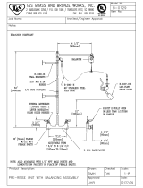
PRESSURE REGULATOR ADJUSTMENT
1. Pull Knob out to unlock.
2. Adjust to 20 psi while faucet
is open, dispensing product.
3. Push knob in to lock.
38465.0000
C
L
O
S
E
O
P
E
N
38466.0000
As directed in the International Plumbing Code of the International Code Council and the Food
Code Manual of the Food and Drug Administration (FDA), this equipment must be installed with
adequate backflow prevention to comply with federal, state and local codes. For models installed
outside the U.S.A., you must comply with the applicable Plumbing /Sanitation Code for your area.
47629 082514

4
1. Remove dispenser from the box and place on a sturdy, level counter.
2. Remove the brass cap and any packing material from the end of the water inlet fitting located on the rear of
the dispenser.
3. Attach a 1/4" water line to the inlet fitting. This supply line must have at least 30 psi of pressure.
4. Using a screwdriver, turn the adjustment screw on the venturi mixer clockwise until the screw contacts the
seat (DO NOT OVERTIGHTEN THIS SCREW!).
5. Turn on the water supply and open the water inlet valve on the rear of the dispenser and check for leaks in
the system.
6. Place a container under faucet(s); fully open the faucet(s) for approximately 10 seconds to remove all the air
out of the lines, then close the faucet(s). Discard the water.
7. Connect the proper BIB (Bag in a Box) adapter(s) to the concentrate inlet tube(s) and clamp. If bottle con-
centrate is used, connect the stainless formed tube(s) to the inlet hose(s) and clamp.
8. Attach the connector(s) to the BIB, or insert the bottle adapter into the bottle(s).
9. Place the concentrate container(s) in the location they will be used for normal operations.
a. In the dispenser housing: Coil the tube in the dispenser and place the BIB (bottle) on top of the coiled
tubing with the connector facing down, under the bag.
b. Under the counter: Place the BIB under the counter and rout the tubing to the dispenser, avoiding sharp
bends and kinks. Cut off excess tubing to keep the over length of tubing to minimum.
NOTE: It is critical that the dispenser is upright and the concentrate container(s) be in the proper location and
orientation that they will be during normal operation, before making any strength adjustments.
10. Slide the dispenser to the edge of the counter to gain access to the adjustment screw from the bottom.
11. Turn the adjustment screw approximately 1/2 turn counterclockwise.
12. Place a container under the faucet(s) and open faucet(s) until the entire concentrate line(s) fill and tea is
dispensed for approximately 5 seconds. Close the faucet(s). Discard this solution.
13. Place a glass under the faucet and open to fill the glass. Adjust the screw to achieve the desired strength
of tea. To increase the amount of concentrate (stronger tea), turn the adjustment screw counterclockwise
slightly (1/16 to 1/8 of a turn at a time). To reduce the amount of concentrate (weaker tea), turn the adjust-
ment screw clockwise slightly (1/16 to 1/8 of a turn at a time).
14. Dispense a couple of 8 ounce glasses of tea after each adjustment and test for taste or color. Continue this
process until the taste or color profile is achieved.
NOTE: The ratio adjustment setting is very sensitive. Make very small adjustments with the screw, then taste or
color check the results. You do not have to turn the screw very much to change the ratio.
15. Once the desired ratio of concentrate to water has been set, slide the dispenser back to the desired location
on the counter top. For under counter BIB’s, make sure the tubes do not get kinked, when the dispenser is
slid back into place.
The dispenser is now ready for use.
SET UP AND OPERATING PROCEDURES
47629 121012

5
Daily Cleaning:
1. Turn handle on rear of dispenser to shut off the water supply.
2. Open the faucet to relieve pressure in the system.
3. Since the bag connector(s) have an internal shut off valve, it will be necessary to prop the valve open during cleaning.
NOTE: Cutting off the mating connector of an empty concentrate bag works well for this. Keep this mating end for future
cleanings of the system.
4. Turn on water supply to the dispenser.
5. Place the open bag connector into a 1/2 gallon container of dish soap and warm to hot water (130° F/54° C).
6. Place a large container under dispenser faucet.
7. Open faucet until the soap/water mixture in the container is empty.
8. After the soap mixture has been flushed through the system, fill the container with warm to hot tap water only (no
soap) and repeat steps 5 thru 7 until all soap has been flushed from the system.
9. Remove the mating end of connector and attach dispenser’s connector to a Bag In a Box and dispense several cups
to prime the concentrate line or until consistency of the product is correct.
10. Wash the entire outside surface of dispenser with a clean, damp cloth.
NOTE: When the system is not in use for extended periods of time (nights, weekends, etc.), turn the water supply valve
off.
Weekly Cleaning:
1. Turn handle on rear of dispenser to shut off the water supply.
2. Open the faucet to relieve pressure in the system.
On models with chrome nut (Complete Step 3, then skip to Step 6):
On models with wing nut (Skip Step 3 - Start at Step 4):
3. Unscrew the faucet bonnet (a) and remove all faucet components, leaving the faucet body (b) in place on the venturi
assembly.
4. Twist the faucet wing nut in a clockwise direction and remove faucet from the dispenser.
5. Remove and clean the O-ring (Optional).
a. Remove the o-ring from the venturi assembly nozzle. Be very careful when removing this o-ring.
Do Not scratch or nick the o-rings sealing surface when removing.
b. Clean the groove and o-ring with the same solutions as used to clean the faucet, Step 6.
c. When finished, slide the o-ring back into the groove on the venturi nozzle.
6. Sanitizing the faucet:
This procedure requires three cleaning solutions of approximately ½ gal each, a mild detergent and warm
water solution, clean hot water only and a warm chlorine solution (at least 50 ppm of chlorine at 75° F [24°
C]). NOTE: DO NOT use full strength bleach.
a. Disassemble the faucet.
b. Thoroughly wash all faucet parts in the mild detergent solution.
c. Rinse the parts in hot water.
d. Sanitize the parts by soaking for one minute in the warm chlorine solution.
e. Re-rinse the parts in hot water to remove all the chlorine solution.
f. Reassemble the faucet and attach it to the dispenser.
7. Sanitizing the BIB connector, tubing and metering valve:
This procedure requires a 1/2 gallon container of sanitizing solution, (100 ppm of chlorine at 100° F (38°
C) water).
a. Since the bag connector(s) have an internal shut off valve, it will be necessary to prop the valve open during clean-
ing. NOTE: Cutting off the mating connector of an empty concentrate bag works well for this. Keep this mating end for
future cleanings of the system.
b. Turn on water supply to the dispenser.
c. Place open bag connector into the 1/2 gallon container of sanitizing solution.
d. Place a large container under dispenser faucet.
e. Open faucet until the chlorine mixture in the container is empty.
f. Allow dispenser to sit overnight before flushing sanitizer out of the system.
g. Flush system by filling a container with warm to hot tap water only (no chlorine) and opening the faucet - until all
chlorine has been flushed from the system.
8. Remove the mating end of connector and attach dispenser’s connector to a Bag In a Box and dispense several cups
to prime the concentrate line or until consistency of the product is correct.
DISPENSER CLEANING AND SANITIZING
a
b
47629 121012

6
TCD-1
TCD-2
REPLACEMENT PARTS (TCD-1)
6
7
8
9
2
3
1
4
5
14
13
12
11
10
15
16
17
18
19
20
20
44
45
21
20
22
23
24
26
25
26
27
28
29
31
32
33
42
20
43
.375" BIB Adapter
56
57
58
57
Concentrate Bottle Tube
47
48
49
50
54
46
30
52 51
53
55
47
20
19
59
34
35
36
37
38
39
41
40
60
Early Models
P3457.60
61
Early Models
47629 121012

ITEM PART NO. QTY. DESCRIPTION
7
* Indicates the part number listed is for reference only. See DESCRIPTION for possible service replacement.
1 23820.1000 1 Water Strainer Assy (Includes items 2 thru 4)
2 22249.0000 1 Cap, Water Strainer
3 23721.0000 1 Screen
4 23819.0000* 1 Housing (Order item 1)
5 00310.0006 1 Tube Assy, Strainer to Bulkhead
6 00459.0001 1 Fitting, Bulkhead
7 01532.0000 1 Lockwasher, Internal Tooth .438"
8 00463.0000 1 Nut, .438" - 20
9 37689.0000 1 Tube Assy, Bulkhead to Shut-off
10 32891.0001 1 Elbow, Male .25" FLR x .25" MPT
11 33113.0000 1 Valve, Ball .25" FPT x .25" FPT
12 32360.0001 1 Clamp, .613" ID
01315.0000 1 Screw, Truss Head #8-32 x .375"
00991.0000 1 Nut #8-32
13 37898.0000 1 Gauge, Pressure
14 37742.0001 1 Nipple, .25" MPT
15 00432.0001 1 Elbow, .125" NPT Male/Female
16 00430.0001 1 Adapter, .125" NPT Male/Female
17 21993.0005 1 Regulator, Water, Low Flow (TCD models except 37750.0037 & 37750.0038)
21993.0006 1 Regulator, Water, Low Flow (TCD models 37750.0037 & 37750.0038 only)
18 37460.0000 1 Fitting, Barb Elbow .25" NPT
19 37720.0001* 2 Tube, Silicone .375" ID x 5.25" (Order item 64)
20 12422.0001 8 Clamp, Hose .59"/.66"
21 40071.0015 2 Valve, Check .375" Barb
22 37720.0004* 1 Tube, Silicone .375" ID x 1.75" (Order item 64)
23 37736.1000 1 Venturi Assy (.25" product tubing)(Includes item 24,25, 27-29 & 32)
37736.1001 1 Venturi Assy (.375" product tubing)(Includes item 24 thru 29 & 32)
37736.1002 1 Venturi Assy w/Barbs (.375" tubing)(Includes item 28, 29 & 30)(Late Models)
38044.0000 2 Screw, Plastite #6 x .375"
24 43111.0000 1 Plate, Fitting Retainer
01360.0002 2 Screw, Plascrew #6 x .375"
25 32849.0001 2 O-ring
26 32631.1002 2 Fitting, Barb .375"
(continued)
REPLACEMENT PARTS (TCD-1)
NOTE: Effective August 2006, the Venturi and product delivery tubing was changed from .25"ID to .375"ID to improve
flow rate. If for first replacement, order Tube Replacement Kit P/N 39169.0000 (2 kits required for TCD-2)
Early Models
Early
Models
47629 062519

8
TCD-1
TCD-2
REPLACEMENT PARTS (TCD-1)
(continued)
P3457.60
6
7
8
9
2
3
1
4
5
14
13
12
11
10
15
16
17
18
19
20
20
44
45
21
20
22
23
24
26
25
26
27
28
29
31
32
33
42
20
43
.375" BIB Adapter
56
57
58
57
Concentrate Bottle Tube
47
48
49
50
54
46
30
52 51
53
55
47
20
19
59
34
35
36
37
38
39
41
40
60
Early Models
61
Early Models
47629 121012

ITEM PART NO. QTY. DESCRIPTION
9
* Indicates the part number listed is for reference only. See DESCRIPTION for possible service replacement.
27 - - - - - - - - 1 Venturi Mixer (Order item 23)
28 37691.0000 1 O-ring
29 37486.0000 1 Adjustment Screw, Venturi
30 32852.0000 1 O-ring
31 03093.0001 1 Wing Nut, Faucet
01268.0000 1 Chrome Nut, Faucet Union (Optional)
32 01221.0001 1 C-Ring, Faucet Shank
33 03260.0034 1 Faucet Assy, Black Plastic Body (Includes items 34 thru 40)(Refer to page 18 for
important ordering information)(See item 67)
03260.0005 1 Faucet Assy, Chrome Body (Includes items 34 thru 41)(See item 67)
34 29163.0007 1 Handle, Faucet
29163.0012 1 Handle, Faucet (SWEET)
29163.0013 1 Handle, Faucet (UNSWEET)
35 29165.0002 1 Bonnet, Faucet
36 00601.0001 1 Spring Faucet
37 37715.0000 1 Collar, Spring (Refer to item 66)
38 29164.0000 1 Stem, Faucet
39 00600.0001 1 Seat Cup, Faucet (Refer to item 66)
40 35758.0002* 1 Faucet Body, Black Plastic (Order item 33)
35206.0000* 1 Faucet Body, Chrome (Order item 33)
41 38473.0000 1 Insert
42 - - - - - - - - 1 Tube, Silicone .25" ID x 36.0" (For first replacement, order item 59)
20976.0078* 1 Tube, Silicone .375" ID x 60.0" (Order item 64)
43 34093.0000 1 Lid, Reservoir
44 01592.0000 2 Bushing, 1.0" Dia
45 03043.0006 1 Decal, Iced Tea (See page 18 for proper placement)
46 38130.0000 1 Decal, Faucet Under Pressure
47 38278.0002* 2 Edging 36.0" (Order item 69)
48 38029.1000 1 Drip Tray Assy (Includes items 49 & 50)
49 26801.0000 1 Drip Tray Cover
50 03207.0004 1 Drip Tray
51 38465.0000 1 Decal, Pressure Regulator
52 38466.0000 1 Decal, Shut-off
REPLACEMENT PARTS (TCD-1)
(continued)
Optional
47629 052118

10
TCD-1
TCD-2
REPLACEMENT PARTS (TCD-1)
(continued)
P3457.60
6
7
8
9
2
3
1
4
5
14
13
12
11
10
15
16
17
18
19
20
20
44
45
21
20
22
23
24
26
25
26
27
28
29
31
32
33
42
20
43
.375" BIB Adapter
56
57
58
57
Concentrate Bottle Tube
47
48
49
50
54
46
30
52 51
53
55
47
20
19
59
34
35
36
37
38
39
41
40
60
Early Models
61
Early Models
47629 121012

ITEM PART NO. QTY. DESCRIPTION
11
* Indicates the part number listed is for reference only. See DESCRIPTION for possible service replacement.
REPLACEMENT PARTS (TCD-1)
53 00651.0000 1 Decal, BUNN
54 00656.0001 1 Decal, Plumbing Code
55 38839.0000 1 Stand (Optional)
56 26443.0000 1 Reducer, Barb .375" x .25"
34644.0000 1 Connector, Barb .375" x .375"
57 12422.0001 2 Clamp, Hose .59"/.66"
58 37720.0000* 1 Tube, Silicone .375" ID x 3.0" (Order item 64)
59 37744.0000 1 Tube, Concentrate Bottle .25"
37744.0001 1 Tube, Concentrate Bottle .375"
60 39216.0000 1 Screen Filter (Late Models)
61 27574.0000 1 Sealing Washer
The Following Items Are Not Illustrated
62 00674.0000 1 Brush, Tube .75"
00674.1000 1 Brush, Tube .75" (Includes 6 Brushes)
63 M2531.0000 1 Lube&Sealant Compound
64 37721.1000 - Tube, Silicone .25" ID x 12.0"
37721.1001 - Tube, Silicone .25" ID x 36.0"
37721.1002 - Tube, Silicone .25" ID x 120.0"
65 20976.1000 - Tube, Silicone .375" ID x 12.0"
20976.1001 - Tube, Silicone .375" ID x 36.0"
20976.1002 - Tube, Silicone .375" ID x 120.0"
66 37747.1000 - Parts Bag (Includes items 1,5,20,33,45 & 59)(with 3.0" BIB hose)
37747.1001 - Parts Bag (Includes items 1,5,20,33,48,58 & 59)(with 36.0" BIB hose)
67 38471.0000 - Kit, Faucet Seat Cup (Includes items 37 & 39)
68 28707.0004 - Kit, Faucet Repair (Includes items 34 & 36-39)
69 38278.1002 - Edging 36.0" (Use as required)
70 39169.0000 - Tube Replacement Kit (Includes items 20,21,22,26 & 42)
For use with .375" BIB adapter
Optional
47629 121012

12
TCD-1
TCD-2
REPLACEMENT PARTS (TCD-2)
P3462.60
64
6
7
8
9
14
13
12
11
10
15
16
17
18
24
19
48
21
20
25
25
26
27
28
29
30
29
31
32
33
35
36
38
39
40
41
42
43
45
44
37
59
46
48
51
.375" BIB Adapter
47
48
49
48
63
Bag Divider
23
22
52
53
54
55
56
34
58
57
50
Concentrate Bottle Tube
61
60
62
60
24
24
2
3
1
4
5
Early Models
65
Early Models
47629 121012

ITEM PART NO. QTY. DESCRIPTION
13
* Indicates the part number listed is for reference only. See DESCRIPTION for possible service replacement.
1 23820.1000 1 Water Strainer Assy (Includes items 2 thru 4)
2 22249.0000 1 Cap, Water Strainer
3 23721.0000 1 Screen
4 23819.0000* 1 Housing (Order item 1)
5 00310.0006 1 Tube Assy, Strainer to Bulkhead
6 00459.0001 1 Fitting, Bulkhead
7 01532.0000 1 Lockwasher, Internal Tooth .438"
8 00463.0000 1 Nut, .438" - 20
9 37689.0000 1 Tube Assy, Bulkhead to Shut-off
10 32891.0001 1 Elbow, Male .25" FLR x .25" MPT
11 33113.0000 1 Valve, Ball .25" FPT x .25" FPT
12 32360.0001 1 Clamp, .613" ID
01315.0000 1 Screw, Truss Head #8-32 x .375"
00991.0000 1 Nut #8-32
13 37898.0000 1 Gauge, Pressure
14 37742.0001 1 Nipple, .25" MPT
15 00432.0001 1 Elbow, .125" NPT Male/Female
16 00430.0001 1 Adapter, .125" NPT Male/Female
17 21993.0005 1 Regulator, Water, Low Flow (TCD models except 37750.0037 & 37750.0038)
21993.0006 1 Regulator, Water, Low Flow (TCD models 37750.0037 & 37750.0038 only)
18 37460.0000 1 Fitting, Barb Elbow .25" NPT
19 37720.0004* 2 Tube, Silicone .375" ID x 1.75" (Order item 68)
20 38023.0000 1 Y-Fitting, Barb .25" Hose
21 01592.0000 4 Bushing, 1.0" Dia
22 37720.0001* 2 Tube, Silicone .375" ID x 5.25" (Order item 68)
23 03043.0006 1 Decal, Iced Tea (See page 18 for proper placement)
24 12422.0001 16 Clamp, Hose .59"/.66"
25 40071.0015 3 Valve, Check .375"
26 - - - - - - - - 2 Tube, Silicone .25" ID x 3.5" (If for first replacement, order item 73)
37720.0004* 2 Tube, Silicone .375" ID x 1.75" (Order item 68)
27 37736.1000 2 Venturi Assy (.25" product tubing)(Each includes items 28,30-33 & 36)
37736.1001 2 Venturi Assy (.375" product tubing)(Each includes items 28 thru 33 & 36)
37736.1002 2 Venturi Assy w/Barbs (.375" tubing)(Includes item 32, 33 & 35)(Late Models)
01360.0002 4 Screw, Plascrew #6 x .375"
28 43111.0000 1 Plate, Fitting Retainer
38044.0000 2 Screw, Plastite #6 x .375"
REPLACEMENT PARTS (TCD-2)
(continued)
NOTE: Effective August 2006, the Venturi and product delivery tubing was changed from .25"ID to .375"ID to improve
flow rate. If for first replacement, order Tube Replacement Kit P/N 39169.0000 (2 kits required for TCD-2)
Early Models
Early
Models
47629 062519

14
TCD-1
TCD-2
P3462.60
REPLACEMENT PARTS (TCD-2)
(continued)
64
6
7
8
9
14
13
12
11
10
15
16
17
18
24
19
48
21
20
25
25
26
27
28
29
30
29
31
32
33
35
36
38
39
40
41
42
43
45
44
37
59
46
48
51
.375" BIB Adapter
47
48
49
48
63
Bag Divider
23
22
52
53
54
55
56
34
58
57
50
Concentrate Bottle Tube
61
60
62
60
24
24
2
3
1
4
5
Early Models
65
Early Models
47629 121012

ITEM PART NO. QTY. DESCRIPTION
15
* Indicates the part number listed is for reference only. See DESCRIPTION for possible service replacement.
29 32631.1002 2 Fitting, Barb .375"
30 32849.0001 2 O-ring
31 - - - - - - - - 1 Venturi Mixer (Order item 27)
32 37691.0000 1 O-ring
33 37486.0000 1 Adjustment Screw, Venturi
34 03093.0001 2 Wing Nut, Faucet
01268.0000 2 Chrome Nut, Faucet Union (Optional)
35 32852.0000 2 O-ring
36 01221.0001 2 C-Ring, Faucet Shank
37 03260.0034 2 Faucet Assy, Black Plastic Body (Includes items 38 thru 44)(Refer to page 18 for
important ordering information)(See item 71)
03260.0005 2 Faucet Assy, Chrome Body (Includes items 38 thru 45)(See item 71)
38 29163.0007 1 Handle, Faucet
29163.0012 1 Handle, Faucet (SWEET)
29163.0013 1 Handle, Faucet (UNSWEET)
39 29165.0002 1 Bonnet, Faucet
40 00601.0001 1 Spring Faucet
41 37715.0000 1 Collar, Spring (Refer to item 70)
42 29164.0000 1 Stem, Faucet
43 00600.0001 1 Seat Cup, Faucet (Refer to item 70)
44 35758.0002* 1 Faucet Body, Black Plastic (Order item 37)
35206.0000* 1 Faucet Body, Chrome (Order item 37)
45 38473.0000 1 Insert
46 - - - - - - - - 2 Tube, Silicone .25" ID x 36.0" (If for first replacement, order item 73)
20976.0078* 2 Tube, Silicone .375" ID x 60.0" (Order item 68)
47 26443.0000 2 Reducer, Barb .375" x .25"
34644.0000 2 Connector, Barb .375" x .375"
48 12422.0001 12 Clamp, Hose .59"/.66"
49 37720.0000* 2 Tube, Silicone .375" ID x 3.0" (Order item 68)
50 37744.0000 2 Tube, Concentrate Bottle .25"
37744.0001 2 Tube, Concentrate Bottle .375"
51 34093.0000 1 Lid, Reservoir
52 38029.1000 1 Drip Tray Assy (Includes items 53 & 54)
53 26801.0000 1 Drip Tray Cover
54 03207.0004 1 Drip Tray
55 00656.0001 1 Decal, Plumbing Code
56 38130.0000 1 Decal, Faucet Under Pressure
REPLACEMENT PARTS (TCD-2)
(continued)
For use with .375" BIB adapter
Optional
Optional
47629 052118

16
TCD-1
TCD-2
REPLACEMENT PARTS (TCD-2)
P3462.60
(continued)
64
6
7
8
9
14
13
12
11
10
15
16
17
18
24
19
48
21
20
25
25
26
27
28
29
30
29
31
32
33
35
36
38
39
40
41
42
43
45
44
37
59
46
48
51
.375" BIB Adapter
47
48
49
48
63
Bag Divider
23
22
52
53
54
55
56
34
58
57
50
Concentrate Bottle Tube
61
60
62
60
24
24
2
3
1
4
5
Early Models
65
Early Models
47629 121012

ITEM PART NO. QTY. DESCRIPTION
17
* Indicates the part number listed is for reference only. See DESCRIPTION for possible service replacement.
REPLACEMENT PARTS (TCD-2)
57 38465.0000 1 Decal, Pressure Regulator
58 38466.0000 1 Decal, Shut-off
59 00651.0000 1 Decal, BUNN
60 38278.0002* 2 Edging 36.0" (Order item 73)
61 38839.0000 1 Stand
62 38745.1000 1 Bag Divider (Includes Item 63)
63 38278.0001* 1 Edging 9.5" (Order item 72)
38278.0003* 2 Edging 1.0" (Order item 72)
64 39216.0000 1 Screen Filter (Late Models)
65 27574.0000 1 Sealing Washer
The Following Items Are Not Illustrated
66 00674.0000 1 Brush, Tube .75"
00674.1000 1 Brush, Tube .75" (Includes 6 Brushes)
67 M2531.0000 1 Lube&Sealant Compound
68 37721.1000 - Tube, Silicone .25" ID x 12.0"
37721.1001 - Tube, Silicone .25" ID x 36.0"
37721.1002 - Tube, Silicone .25" ID x 120.0"
69 20976.1000 - Tube, Silicone .375" ID x 12.0"
20976.1001 - Tube, Silicone .375" ID x 36.0"
20976.1002 - Tube, Silicone .375" ID x 120.0"
70 37747.1002 - Parts Bag (Includes items 1,5,23,37,48 & 50)(with 3.0" BIB hose)
37747.1003 - Parts Bag (Includes items 1,5,37,47,48,49,50 & 52)(with 36.0" BIB hose)
71 38471.0000 - Kit, Faucet Seat Cup (Includes items 41 & 43)
72 28707.0004 - Kit, Faucet Repair (Includes items 38 & 40-43)
73 38278.1002 - Edging 36.0" (Use as required)
74 39169.0000 - Tube Replacement Kit (Includes items 25,29,46,48-50)(Two Kits required for TCD-2)
47629 121012

18
ICED TEA DECAL PLACEMENT
APPR
OX.
5“
PLASTIC BODY FAUCET COMPARISON
If you have a plastic body faucet of this
design, you must order a complete new
plastic faucet.
New Plastic Faucet Design
47629 121012
/