Miller KB148441 Owner's manual

Category
Welding System
Type
Owner's manual

This manual is also suitable for

cover2 8/91 SB-144 451 PRINTED IN USA
February 1992 FORM: OM-1078A
Effective With Serial No. KB148441
MODEL: WC-24
WC-115A
WC-115W
IMPORTANT: Read and understand the entire contents of both this manual and
the power source manual used with this unit, with special emphasis on the safety
material throughout the manual, before installing, operating, or maintaining this
equipment. This unit and these instructions are for use only by persons trained
and experienced in the safe operation of welding equipment. Do not allow
untrained persons to install, operate, or maintain this unit. Contact your distributor
if you do not fully understand these instructions.
MILLER ELECTRIC Mfg. Co.
A Miller Group Ltd., Company
P.O. Box 1079
Appleton, WI 54912 USA
Tel. 414-734-9821
OWNER’S MANUAL
OM-1078A - 2/92
TABLE OF CONTENTS
SECTION 1 SAFETY SIGNAL WORDS 1. . . . . . . . . . . . . . . . . . . . . . . . . . . . . . . . . . . . . . . . . . . . . . . . . .
SECTION 2 SPECIFICATIONS 1. . . . . . . . . . . . . . . . . . . . . . . . . . . . . . . . . . . . . . . . . . . . . . . . . . . . . . . . . .
SECTION 3 INSTALLATION
3-1. Location 2. . . . . . . . . . . . . . . . . . . . . . . . . . . . . . . . . . . . . . . . . . . . . . . . . . . . . . . . . . . . . . . . . . . . . .
3-2. 24 Volt Model Connections 2. . . . . . . . . . . . . . . . . . . . . . . . . . . . . . . . . . . . . . . . . . . . . . . . . . . . . .
3-3. Connections From Gun/Feeder 3. . . . . . . . . . . . . . . . . . . . . . . . . . . . . . . . . . . . . . . . . . . . . . . . . .
3-4. Shielding Gas Connections 4. . . . . . . . . . . . . . . . . . . . . . . . . . . . . . . . . . . . . . . . . . . . . . . . . . . . . .
3-5. Water Connections (Water Cooled Models Only) 5. . . . . . . . . . . . . . . . . . . . . . . . . . . . . . . . . . .
3-6. Coolant Guidelines To Prevent Corrosion 5. . . . . . . . . . . . . . . . . . . . . . . . . . . . . . . . . . . . . . . . .
3-7. 115 Volt Model Voltage Sensing Cable Connections And Motor Start Control Adjustment 6
3-8. Weld Cable Connections 7. . . . . . . . . . . . . . . . . . . . . . . . . . . . . . . . . . . . . . . . . . . . . . . . . . . . . . . .
3-9. 115 Volt Model Input Connections 8. . . . . . . . . . . . . . . . . . . . . . . . . . . . . . . . . . . . . . . . . . . . . . . .
3-10. Contact Closure Connections 10. . . . . . . . . . . . . . . . . . . . . . . . . . . . . . . . . . . . . . . . . . . . . . . . . . . .
SECTION 4 OPERATION 11. . . . . . . . . . . . . . . . . . . . . . . . . . . . . . . . . . . . . . . . . . . . . . . . . . . . . . . . . . . . . . .
SECTION 5 MAINTENANCE & TROUBLESHOOTING
5-1. Routine Maintenance 15. . . . . . . . . . . . . . . . . . . . . . . . . . . . . . . . . . . . . . . . . . . . . . . . . . . . . . . . . . .
5-2. Overload Protection 15. . . . . . . . . . . . . . . . . . . . . . . . . . . . . . . . . . . . . . . . . . . . . . . . . . . . . . . . . . . .
5-3. Troubleshooting 15. . . . . . . . . . . . . . . . . . . . . . . . . . . . . . . . . . . . . . . . . . . . . . . . . . . . . . . . . . . . . . .
SECTION 6 ELECTRICAL DIAGRAMS 17. . . . . . . . . . . . . . . . . . . . . . . . . . . . . . . . . . . . . . . . . . . . . . . . . . .
SECTION 7 PARTS LIST
Figure 7-1. Main Assembly 20. . . . . . . . . . . . . . . . . . . . . . . . . . . . . . . . . . . . . . . . . . . . . . . . . . . . . . . . . . . .
Figure 7-2. WC-24 Control 23. . . . . . . . . . . . . . . . . . . . . . . . . . . . . . . . . . . . . . . . . . . . . . . . . . . . . . . . . . . . .
OM-1078 Page 1
SECTION 1 SAFETY SIGNAL WORDS
mod1.1 9/91
The following safety alert symbol and signal words are used throughout this manual to call attention to and identify
different levels of hazard and special instructions.
WARNING
WARNING statements identify procedures or practices which must be followed to avoid serious personal
injury or loss of life.
CAUTION
CAUTION statements identify procedures or practices which must be followed to avoid minor personal
injury or damage to this equipment.
IMPORTANT: statements identify special instructions necessary for the most efficient operation of this equipment.
SECTION 2 SPECIFICATIONS
Table 2-1. Weld Control Specifications
Specification 24 Volt Models 115 Volt Models
Input Power Single-Phase 24 Volts AC, 1 Ampere,
50/60 Hertz Or 100 Hertz
Single-Phase 115 Volts AC, 2 Amperes,
50/60 Hertz Or 100 Hertz
Control Circuit Voltage Provided To
Gun/Feeder
30 Volts DC 30 Volts DC
Welding Power Source Type Constant Voltage (CV) DC, With Contactor Constant Current (CC) Or Constant Voltage (CV)
DC, With Contactor
Cooling Method Air Cooled (A Models) Or Water Cooled (W Mod-
els)
Coolant Requirements (Water-Cooled
Models)
1 qt./min. Minimum Flowrate
Use Distilled Or Deionized Water, Or High-Qual-
ity Tap Water
Connections Gun Trigger Controls Gun Trigger Controls, Gas, Weld Cables, And
Water In Water-Cooled Models
Welding Process DC Gas Metal Arc Welding (GMAW) DC Gas Metal Arc Welding (GMAW)
Optional Equipment Spot/Continuous Switch, Time Range Switch,
Spot Time Control, Contactor, And Burnback
Control
Input Power Cord With Plug 5 ft. (1.5 m) 9 ft. (2.7 m)
Overall Dimensions See Figure 3-1 See Figure 3-1
Weight Net: 2 lbs. (0.9 kg); Ship: 3 lbs. (1.4 kg) Net: 20 lbs. (9 kg); Ship: 23 lbs. (10.4 kg)
OM-1078 Page 2
SECTION 3 INSTALLATION
3-1. Location
B
Turn OFF welding power source.
1 24 Volt Model
2 115 Volt Model
Place unit on a bench, or on the
welding power source.
SA-147 743 / SB-144 451
A
B
C
A
D
C
A
B
C
D
Inches
7-3/8
5-1/2
1-3/4
6
Millimeters
187
140
44
153
24 Volt Models
8-5/8
9-1/4
12-1/4
219
235
311
115 Volt Models
A
B
C*
1
2
*For Water Cooled Model add 5 in.
(126 mm) for strain relief.
Figure 3-1. Overall Dimensions And Mounting Hole Layout
3-2. 24 Volt Model Connections
Ref. ST-151 355
1 14-Pin Plug PLG4 And Inter-
connecting Cord
Insert plug into 14-socket recep-
tacle on welding power source, and
rotate threaded collar fully clock-
wise.
2 Welding Power Source Top Or
Side Panel Screw
Install unit onto welding power
source.
3 Trigger Control Receptacle
4 Gun/Feeder Trigger Control
Cord And 10-Pin Plug
Insert 10-pin plug from gun/feeder
into receptacle, and rotate threaded
collar fully clockwise. (See gun/fe-
eder Owners Manual).
Tools Needed:
2
1
1/4 in.
3
4
Figure 3-2. 24 Volt Model Connections
OM-1078 Page 3
3-3. Connections From Gun/Feeder
A. Air Cooled Models
1 Gun Control Receptacle
2 Weld Power Grommet
3 Gas Fitting
See gun/feeder Owners Manual
for connections.
Ref. ST-149 549-A / Ref. ST-149 966-A
Tools Needed:
Left Side
Wrapper Off
1
3
2
2
3/4 in.
Figure 3-3. Connections From Gun/Feeder To Air Cooled Models
B. Water Cooled Models
Ref. ST-152 445
1 Gun Control Receptacle
2 Weld/Water From Gun Fitting
3 Strain Relief
4 Gas Fitting
5 Water To Gun Fitting
See gun/feeder Owner’s Manual for
connections.
1
2
3
4
5
1-1/8 in., 5/8 in.
Tools Needed:
Figure 3-4. Connections From Gun/Feeder To Water Cooled Models
OM-1078 Page 4
3-4. Shielding Gas Connections
WARNING
ELECTRIC SHOCK can kill.
Do not touch live electrical parts.
Turn OFF weld control and welding power source, and disconnect input power before inspecting or installing. Stop engine on
welding generators.
A. Air Cooled Models
ELECTRIC SHOCK HAZARD. Read safety information at beginning of Section 3-4 be-
fore proceeding.
ST-149 920 / Ref. ST-149 549-A / Ref. S-0621-C
1 Lower Right Grommet On
Rear Panel
2 Regulator/Flowmeter
3 Gas Hose (supplied with gun/
feeder)
Connect one end of gas hose to re-
gulator/flowmeter. Route remaining
end of hose through lower right
grommet in rear panel, and connect
to rear of front panel GAS fitting.
4 Rear Of Front Panel Gas Fit-
ting
5 Gun/Feeder Gas Hose
See gun/feeder Owner’s Manual for
installation instructions.
Reinstall wrapper.
5/8 in.
2
Tools Needed:
1/4 in.
Rear
Front Panel
Opening
34 5
1
Figure 3-5. Shielding Gas Connections In Air Cooled Models
B. Water Cooled Models
ELECTRIC SHOCK HAZARD. Read safety information at beginning of Section 3-4 be-
fore proceeding.
ST-149 920 / Ref. ST-148 102-B / Ref. S-0621-C
1 Lower Right Grommet On
Rear Panel
2 Regulator/Flowmeter
3 Gas Hose (supplied with gun/
feeder)
Connect one end of gas hose to re-
gulator/flowmeter. Route remaining
end of hose through lower right
grommet in rear panel, and connect
to rear of front panel GAS fitting.
4 Rear Of Front Panel Gas Fit-
ting
Reinstall wrapper.
See gun/feeder Owner’s Manual for
instructions on installing gun/feeder
gas hose.
5/8 in.
2
Tools Needed:
1/4 in.
Rear
Front Panel
Opening
34
1
Figure 3-6. Shielding Gas Connections In Water Cooled Models
WARNING
WARNING
OM-1078 Page 5
3-5. Water Connections (Water Cooled Models Only)
WARNING
ELECTRIC SHOCK can kill.
Do not touch live electrical parts.
Turn OFF weld control and welding power source,
and disconnect input power before inspecting or
installing. Stop engine on welding generators.
OVERHEATING can damage gun parts.
If using recirculating coolant system, do not make
connections from coolant system to water valve;
instead make connections directly from coolant
system to gun hoses.
INCORRECT COOLANT FLOWRATE
can damage gun parts.
Maintain minimum 1 qt./min. flowrate at all times.
1 Upper Right Grommet On
Rear Panel
2 10 Ft. (3 m) Water Supply
Hose With 5/8 in. Adapter
Fitting
3 Rear Of Front Panel Water To
Gun Fitting
Remove 5/8 in. adapter fitting from
hose. Route one end of a water
hose through grommet, and con-
nect to rear of WATER TO GUN fit-
ting on front panel. Connect re-
maining end of hose to supply fitting
on coolant supply. All water con-
nections have 5/8 in. left-hand
threads.
4 Upper Left Grommet On Rear
Panel
5 10 Ft. (3 m) Water Return
Hose
6 Connection Block
Route one end of remaining water
hose through grommet, and con-
nect to rear of connection block.
Connect remaining end of hose to
return fitting on coolant supply.
Reinstall wrapper.
ST-149 290 / Ref. ST-148 102-B / Ref. ST-139 440-A
Rear
56 3
2
1/4 in.
5/8 in.
Tools Needed:
1
4
Figure 3-7. Water Connections
3-6. Coolant Guidelines To Prevent Corrosion
Prevent corrosion in the gun/feeder and cooling system by following these guidelines:
1. Add chlorine bleach to the coolant system to remove algae as follows:
a. For coolant systems with a capacity of 2 gallons (7.6 L) or less, add 1/2 oz. (15 ml) bleach.
b. For coolant systems with a capacity greater than 2 gallons (7.6 L), add 1 oz. (30 ml) bleach.
Using more than the specified amount of bleach in the coolant system will increase corrosion and shorten the
life of the system.
2. If operating at temperatures below freezing, use an ethylene glycol solution (Miller Part No. 128 705) in the
coolant system. Do not use automotive-type antifreezes that contain anti-leak compounds which could block
torch cooling passages.
3. Do not change coolant unless it is discolored or dirty. Add soft, high-quality tap water, deionized water, or dis-
tilled water to maintain coolant level.
4. Be sure electrical connections are tight. Do not make electrical connections with connectors made of different
metals.
OM-1078 Page 6
3-7. 115 Volt Model Voltage Sensing Cable Connections And Motor Start Control Adjust-
ment
WARNING
ELECTRIC SHOCK can kill.
Do not touch live electrical parts.
Turn OFF weld control and welding power source,
and disconnect input power before inspecting or
installing. Stop engine on welding generators.
STATIC ELECTRICITY can damage
parts on circuit boards.
Put on grounded wrist strap BEFORE handling
boards or parts.
Use proper static-proof bags and boxes.
1 Center Baffle
2 Circuit Board PC1
3 Jumper Plug
4 Receptacle RC3
Internal (INT) and external (EXT)
are stamped on PC1 just above
RC3. Unit is shipped with jumper
plug in internal (INT) position.
5 Potentiometer R70
6 Voltage Sensing lead
For constant current welding (CC),
place jumper plug in the EXT posi-
tion. Connect voltage sensing lead
to workpiece.
For constant voltage welding (CV),
place jumper plug in the INT posi-
tion. Do not connect voltage sens-
ing lead.
To adjust motor ramp speed, re-
move protective cap (if present),
and adjust potentiometer R70 using
a small nonconductive screwdriver.
Rotating R70 clockwise increases
the time it takes the motor to ramp
up to speed.
Reinstall wrapper.
ST-149 920 / ST-150 035
Tools Needed:
6
Front
1
2
3
4
5
Rear
123
INT. EXT.
RC3
1/4 in.
Figure 3-8. Voltage Sensing Cable Connections And Motor Start Control Potentiometer R70
OM-1078 Page 7
3-8. Weld Cable Connections
WARNING
ELECTRIC SHOCK can kill.
Do not touch live electrical parts.
Turn OFF weld control and welding power source, and disconnect input power before inspecting or installing. Stop engine on
welding generators.
A. Air Cooled Models
ELECTRIC SHOCK HAZARD. Read safety information at beginning of Section 3-8 be-
fore proceeding.
ST-149 920 / ST-151 113 / ST-149 549-A / Ref. SC-139 439-A
1 Lower Left Grommet
2 Positive (+) Weld Output Ter-
minal On Welding Power
Source
3 Reed Switch
4 Weld Cable (customer
supplied)
5 Weld Cable Terminal
Connect one end of weld cable to
positive (+) terminal on welding
power source. Route remaining end
of weld cable through lower left
grommet and through reed switch,
and install cable securely onto
clean weld cable terminal.
6 Weld Power Cable From Gun/
Feeder
Route weld power cable from gun/
feeder through WELD POWER
grommet on front panel, and install
cable securely onto clean weld
cable terminal. Be sure lug on weld
cable terminal and lug on gun/feed-
er weld power cable make contact
with each other.
7 Weld Power Grommet
Reinstall wrapper.
Tools Needed:
3/4 in.
2
3 4 5 6
Rear
1
Front Panel
Opening
7
1/4 in.
+
Figure 3-9. Weld Cable Connections In Air Cooled Models
WARNING
OM-1078 Page 8
B. Water Cooled Models
ELECTRIC SHOCK HAZARD. Read safety information at beginning of Section 3-8 be-
fore proceeding.
ST-149 920 / ST-151 113 / ST-148 102-B
1 Lower Left Grommet
2 Positive (+) Weld Output Ter-
minal On Welding Power
Source
3 Reed Switch
4 Weld Cable (customer
supplied)
5 Weld Cable Terminal
Connect one end of weld cable to
positive (+) terminal on welding
power source. Route remaining
end of weld cable through lower left
grommet and through reed switch,
and install cable securely onto
clean weld cable terminal.
Reinstall wrapper.
Tools Needed:
2
3 4 5
Rear
1
1/4 in.
+
3/4 in.
Figure 3-10. Weld Cable Connections In Water Cooled Models
3-9. 115 Volt Model Input Connections
WARNING
ELECTRIC SHOCK can kill.
Do not touch live electrical parts.
Turn OFF weld control and welding power source, and disconnect input power before inspecting or installing. Stop engine on
welding generator.
Have only qualified persons install unit.
Installation must meet National Electrical Code and all other codes.
DIRECT CURRENT (DC) will damage weld control.
Connect weld control only to 115 volts ac (alternating current) 50 or 60 Hertz.
WARNING
OM-1078 Page 9
A. Input Power Connections
ELECTRIC SHOCK HAZARD. Read safety information at beginning of Section 3-9 be-
fore proceeding.
1 Contact Closure Interconnect-
ing Cord And Plug PLG5
2 Voltage Sensing Lead
3 Grounded Receptacle
A 15 ampere branch circuit pro-
tected by time-delay fuses or circuit
breakers is required.
4 Input Power Cord And Plug
PLG4
Connect input power plug to a prop-
er receptacle.
SB-149 548
1
3
4
2
Figure 3-11. Input Power Connections
B. Optional Connections For Input Power From Welding Power Source
ELECTRIC SHOCK HAZARD. Read safety information at beginning of Section 3-9 be-
fore proceeding.
Pin Information For Contact Closure Interconnecting
Cord Plug PLG5:
Contactor Control
A Contact output signal
B Input control to energize weld contactor. Contact
closure from pin A to pin B completes the circuit.
Input Voltage (Optional Connection)
G 115 volts neutral
I 115 volts hot
K Machine Chassis
Remaining pins are not used.
1 Input Power Cord And Plug
PLG4
Cut plug off.
2 Individual Leads
Strip a small amount of insulation
from cord and from each of the
three leads.
3 Pins
Solder a supplied pin to each of the
three leads.
4 Strain Relief Clamp
5 14-Pin Plug PLG5 And Con-
tact Closure Interconnecting
Cord
Open clamp and slide input power
cord and pins into clamp, and insert
pins into rear of plug PLG5 as fol-
lows:
Black lead into pin I
White lead into pin G
Green lead into pin K
Tighten strain relief clamp.
Tools Needed:
AJ
B
K
I
C
L
NH
D
M
G
E
F
1
5
2
3
1
4
5
Input Power Cord
ConnectionTo
14-Pin Plug
SA-150 078 / Ref. ST-149 548 / Ref.. S-0512
5
1
Figure 3-12. Optional Input Power Connections And 14-Pin Plug Information
WARNING
WARNING
OM-1078 Page 10
3-10. Contact Closure Connections
WARNING
ELECTRIC SHOCK can kill.
Do not touch live electrical parts.
Turn OFF weld control and welding power source, and disconnect input power before inspecting or installing. Stop engine on
welding generators.
Have only qualified persons install unit.
A. Contact Closure Connections To A Remote 14 Receptacle On A Welding Power Source
AJ
B
K
I
C
L
NH
D
M
G
E
F
Ref. S-0004-A / Ref. S-0628
Turn OFF weld control and welding
power source.
1 Remote 14 Receptacle On
Welding Power Source
Insert plug into 14-socket recep-
tacle on welding power source, and
rotate threaded collar fully clock-
wise.
2 Keyway
3 Plug PLG5
4 Threaded Collar
Pin Information
A Contactor output signal
B Input control to energize weld contactor. Contact clo-
sure from pin A to pin B completes the circuit.
Remaining pins are not used.
12
3
4
Figure 3-13. Contact Closure Connections And Pin Information
B. Optional Contact Closure Connections For Welding Power Sources Requiring 115 Volts AC For Contac-
tor Operation
ELECTRIC SHOCK HAZARD. Read safety information at beginning of Section 3-10
before proceeding.
Turn OFF weld control and welding
power source.
1 Contact Closure Interconnect-
ing Cord
2 14-Pin Plug PLG5
Cut plug off.
3 Twistlock Receptacle
Install supplied receptacle onto
cord.
4 Terminal Strip 1T
5 Terminal H
Disconnect white lead from termi-
nal J, and reconnect to terminal H.
6 Jumper Link
Install jumper link between termi-
nals K and J.
Connect twistlock receptacle to
contactor control plug on welding
power source.
Reinstall wrapper.
Ref. ST-150 803
Tools Needed:
1 2
3
Rear
4
5
6
4
1/4 in.
Figure 3-14. Contact Closure Connections For Welding Power Sources Requiring 115 Volts AC
For Contactor Operation
WARNING
OM-1078 Page 11
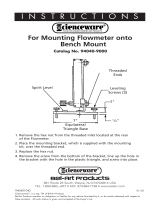
C. Optional Contact Closure Connections For Welding Power Sources Requiring Contact Closure
ELECTRIC SHOCK HAZARD. Read safety information at beginning of Section 3-10
before proceeding.
ST-151 325
Turn OFF weld control and welding
power source.
1 Contact Closure Interconnect-
ing Cord
2 14-Pin Plug PLG5
Cut plug off.
3 Twistlock Plug
Install supplied twistlock plug onto
contact closure interconnecting
cord. Polarity is not important.
Tools Needed:
1 2
3
1
Figure 3-15. Contact Closure Connections For Welding Power Sources Requiring Contact Closure
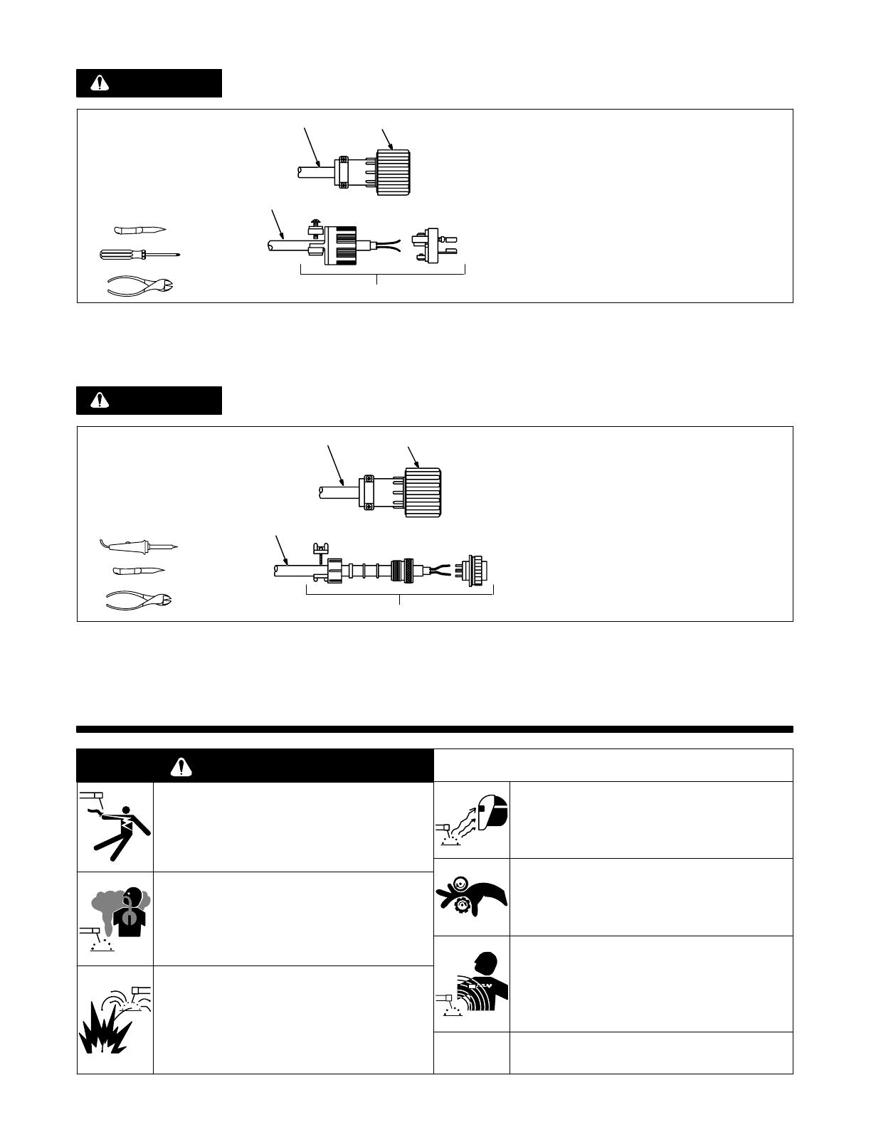
D. Optional Contact Closure Connections For Welding Power Sources Requiring Contact Closure Through
A 5-Pin Plug
ELECTRIC SHOCK HAZARD. Read safety information at beginning of Section 3-10
before proceeding.
ST-151 326
Turn OFF weld control and welding
power source.
1 Contact Closure Interconnect-
ing Cord
2 14-Pin Plug PLG5
Cut plug off.
3 5-Pin Plug
Install supplied 5-pin plug onto con-
tact closure interconnecting cord,
and solder leads to pins A and B.
Tools Needed:
1 2
3
1
Figure 3-16. Contact Closure Connections For Welding Power Sources Requiring Contact Closure
Through A 5-Pin Plug
SECTION 4 OPERATION
WARNING
ELECTRIC SHOCK can kill.
Do not touch live electrical parts.
Always wear dry insulating gloves.
Insulate yourself from work and ground.
Keep all panels and covers securely in place.
FUMES AND GASES can be hazardous
to your health.
Keep your head out of the fumes.
Ventilate area, or use breathing device.
Read Material Safety Data Sheets (MSDSs) and
manufacturer’s instructions for material used.
WELDING can cause fire or explosion.
Do not weld near flammable material.
Watch for fire; keep extinguisher nearby.
Do not locate unit over combustible surfaces.
Do not weld on closed containers.
Allow work and equipment to cool before handling.
ARC RAYS can burn eyes and skin;
NOISE can damage hearing.
Wear welding helmet with correct shade of filter.
Wear correct eye, ear, and body protection.
MOVING PARTS can cause injury.
Keep away from pinch points such as drive rolls.
Keep all doors, panels, covers, and guards closed
and securely in place.
MAGNETIC FIELDS FROM HIGH CUR-
RENTS can affect pacemaker operation.
Pacemaker wearers keep away.
Wearers should consult their doctor before going
near any welding operations.
See Safety Precautions at beginning of manual for ba-
sic welding safety information.
wfwarn3.1 10/91
WARNING
WARNING
OM-1078 Page 12
1 Run-In Speed Control
2 Fuse F1
3 Spot Time Control (Option-
al)
4 Burnback Time Control
(Optional)
5 Time Range Switch (Op-
tional)
6 Spot/Continuous Switch
(Optional)
7 Power Switch
8 Gun Control Receptacle
Ref. ST-144 451
1
2
3
4
5
6
7
8
Figure 4-1. 115 Volt Model Controls
1
1 Insulating Gloves
2 Safety Glasses With Side
Shields
3 Welding Helmet
Wear dry insulating gloves, safety
glasses with side shields, and a
welding helmet with a correct shade
of filter (see ANSI Z49.1).
2 3
sb3.1 10/91
Figure 4-2. Safety Equipment
1 Run-In Speed Control
Use control to select welding
wire speed before arc initiation.
After arc initiation, the wire feed
speed is controlled by the Wire
Speed control on the gun/feeder.
1
ST-139 439
Figure 4-3. Run-In Speed Control
1 Fuse F1
See Section 5-2.
1
Figure 4-4. Fuse F1
OM-1078 Page 13
1 Spot/Continuous Switch
(Optional)
Use switch to select either an un-
timed continuous weld cycle or a
timed spot weld cycle. Both weld
cycles consist of the following
sequence: run-in, weld (spot
time or untimed), and burnback.
2 Time Range Switch (Op-
tional)
Use switch to select spot weld
time range.
3 Spot Time Control (Option-
al)
Use control to select a spot weld
time. Welding wire feeds into
weld at speed selected on the
gun/feeder Wire Speed control.
Spot time starts at arc initiation.
The scale around the control is
marked in seconds.
3
2
1
Figure 4-5. Spot/Continuous Switch, Time Range Switch, And Spot Time Control (Optional)
1 Burnback Time Control
(Optional)
Use control to adjust the time (up
to 0.25 seconds) that the welding
wire is electrically energized af-
ter the wire feeding stops.
By adjusting this control properly,
the welding wire will not freeze in
the weld puddle or in the contact
tube of the gun/feeder. If the
welding wire freezes to the work,
increase the burnback time. If the
welding wire burns back into the
contact tube, decrease the burn-
back time.
1
Figure 4-6. Burnback Time Control (Optional)
1 Power Switch
Use switch to turn unit ON and
OFF.
1
Figure 4-7. Power Switch
OM-1078 Page 14
WARNING
BUILDUP OF SHIELDING GAS can harm health or kill.
Shut off shielding gas supply when not in use.
warn1.1 9/91
1 Customer-Supplied Shielding
Gas Cylinder
2 Valve
Open valve on cylinder just before
welding.
Close valve on cylinder when fin-
ished welding.
3 Regulator/Flowmeter
sb5.1* 10/91 S-0621-B
1
2
3
Figure 4-8. Shielding Gas
Ref. ST-150 755
1 Coolant Supply
Turn on coolant supply before weld-
ing.
Turn off coolant supply when fin-
ished welding.
1
Figure 4-9. Coolant Supply For Water Cooled Model Only
Install &
Connect
Weld Control
Install And Prepare
Gun/Feeder And
Power Source
Put On
Personal Safety
Equipment
Set
All
Controls
Turn On Shielding
Gas And Water
(If Applicable)
Turn On
Weld Control And
Power Source
Do
Sample
Weld
Readjust Controls
And Prepare
For Production
Figure 4-10. Sequence Of Gas Metal Arc Welding (GMAW)
IMPORTANT: When operating in Spot Time mode, gun/feeder trigger must be held closed until SPOT TIME control
has timed out, completing the spot weld cycle. If trigger is released before cycle is complete, cycle stops, and unit
resets for another cycle.
OM-1078 Page 15
SECTION 5 MAINTENANCE & TROUBLESHOOTING
WARNING
ELECTRIC SHOCK can kill.
Do not touch live electrical parts.
Turn OFF weld control and welding power source,
and disconnect input power before inspecting,
maintaining, or servicing. Stop engine on welding
generator.
HOT PARTS can cause severe burns.
Allow cooling period before servicing unit.
Maintenance to be performed only by qualified persons.
5-1. Routine Maintenance
ELECTRIC SHOCK AND HOT PARTS HAZARDS. Read safety information at begin-
ning of Section 5 before proceeding.
Every month check labels, hoses, and cables; clean internal parts.
5-2. Overload Protection
ELECTRIC SHOCK AND HOT PARTS HAZARDS. Read safety information at begin-
ning of Section 5 before proceeding.
Ref. ST-144 451 / Ref. ST-151 186
Turn OFF and unplug unit.
If fuse F1 opens, the weld control
shuts down. To check or change
F1, proceed as follows:
1 Fuse Holder Cover
Press and turn cover counterclock-
wise. Pull out fuse with cover.
2 Fuse
Insert new fuse (see parts list for
size) into cover, and install fuse with
cover by pressing and turning cov-
er clockwise.
12
Figure 5-1. Checking And Replacing Fuse F1
5-3. Troubleshooting
WARNING
ELECTRIC SHOCK can kill.
Do not touch live electrical parts.
Turn OFF welding power source and weld control,
and disconnect input power before inspecting,
maintaining, or servicing.
HOT PARTS can cause severe burns.
Allow cooling period before servicing unit.
Troubleshooting to be performed only by qualified
persons.
WARNING
WARNING
OM-1078 Page 16
Table 5-1. Welding Trouble
Trouble Remedy Section
No weld output; gun feeder inop-
erative.
Secure plug PLG4 in 115 volts ac receptacle. 3-9A
Be sure switch S1 is in the ON position. Figure 4-7
Erratic weld output. Be sure all connections are clean and tight.
Depressing gun/feeder trigger PB1
does not energize weld control;
welding wire is not energized;
shielding gas does not flow.
Be sure gun/feeder trigger plug is secure in GUN CONTROL
receptacle RC3 on weld control.
3-3
Wire feeds, shielding gas flows,
but welding wire is not energized.
Be sure contact closure cord plug PLG5 is secure on welding
power source.
3-10
Be sure contactor control interconnecting cord leads are se-
cure on terminal strip 1T.
3-10
Be sure welding power source is operating correctly. See Trou-
bleshooting Section in welding power source Owner’s Manual.
Wire feeds erratically. Be sure gun/feeder is operating correctly. See Troubleshooting
Section in gun/feeder Owner’s Manual.
Gun overheating (Water-Cooled
Models)
Be sure coolant flowrate is at least 1 qt./min. See gun/feeder
Owner’s Manual
OM-1078 Page 17
SECTION 6 ELECTRICAL DIAGRAMS
Figure 6-1. Circuit Diagram For WC-115A And WC-115W Models
SC-139 435-B
  • Page 1 1
  • Page 2 2
  • Page 3 3
  • Page 4 4
  • Page 5 5
  • Page 6 6
  • Page 7 7
  • Page 8 8
  • Page 9 9
  • Page 10 10
  • Page 11 11
  • Page 12 12
  • Page 13 13
  • Page 14 14
  • Page 15 15
  • Page 16 16
  • Page 17 17
  • Page 18 18
  • Page 19 19
  • Page 20 20
  • Page 21 21
  • Page 22 22
  • Page 23 23
  • Page 24 24
  • Page 25 25
  • Page 26 26

Miller KB148441 Owner's manual

Category
Welding System
Type
Owner's manual
This manual is also suitable for

Ask a question and I''ll find the answer in the document

Finding information in a document is now easier with AI