ADTRAN T1 Quick start guide

Type
Quick start guide

ADTRAN T1, the versatile connectivity solution, seamlessly integrates with your network, offering a plethora of features to optimize your communication experience. Connect to the network T1 circuit via the eight-position modular jack labeled "NET" and utilize the EIA-232 connector for proxy agent, T-WATCH station, ASCII terminal, or modem connectivity. Configure and control the device through the local front panel, EIA-232 control port, or T-WATCH for added convenience.

ADTRAN T1, the versatile connectivity solution, seamlessly integrates with your network, offering a plethora of features to optimize your communication experience. Connect to the network T1 circuit via the eight-position modular jack labeled "NET" and utilize the EIA-232 connector for proxy agent, T-WATCH station, ASCII terminal, or modem connectivity. Configure and control the device through the local front panel, EIA-232 control port, or T-WATCH for added convenience.

T1 ESF CSU ACE P/N 1204025L1
For more detailed documentation, visit us online at www.adtran.com
Quick Start Guide, 61204025L1-13A, August 2004 Technical Support 1-888-4ADTRAN (1-888-423-8726) Copyright 2004 ADTRAN, All Rights Reserved
INSTALLATION INFORMATION
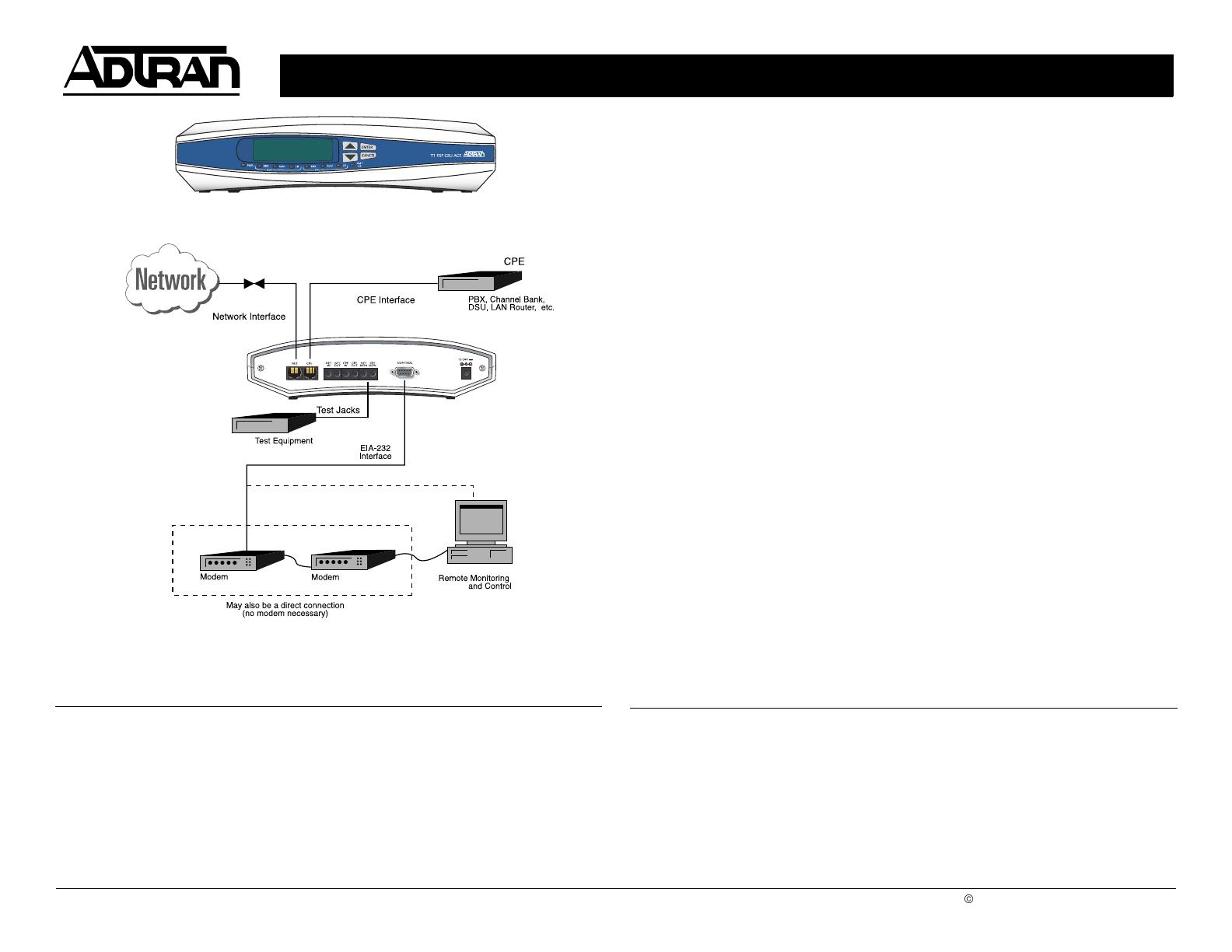
An eight-position modular jack (labeled NET) is provided to connect to
the network T1 circuit. T1 ESF CSU ACE. An eight-position modular
jack (labeled CPE) is provided to connect to the customer equipment.
(The pinouts are provided in this Quick Start Guide. See Chapter 2,
Installation, of the T1 ESF CSU ACE User Manual for more information.)
An EIA-232 connector is provided on the back of the T1 ESF CSU ACE
to connect to a proxy agent, T-WATCH station, ASCII terminal, or
modem. The pinout for the EIA-232 connector can be found in Appendix
A of the the T1 ESF CSU ACE User Manual.
The T1 ESF CSU ACE can be configured and controlled via the local
front panel, the EIA-232 control port, or T-WATCH.
The T1 ESF CSU ACE can be powered by either of the following
methods:
1. Use the included -12 VDC power supply.
2. Use a power cable connected to an on-site 12 to 48 VDC power
supply.
Additional information can be found on the product CD, which contains
the T1 ESF CSU ACE User Manual, FAQs, Data Sheets, Applications,
and White Papers.
NETWORK CONNECTION PINOUT
Pin Name Description
1 R1 RXDATA Receive data from the Network - Ring
2 T1 RXDATA Receive data from the Network - Tip
3, 6, 7, 8 UNUSED n/a
4 R TXDATA Transmit data towards the Network -
Ring
5 T TXDATA Transmit data towards the Network - Tip
CPE CONNECTION PINOUT
Pin Name Description
1 R TXDATA Transmit data towards the Network -
Ring
2 T TXDATA Transmit data towards the Network - Tip
3, 6, 7, 8 UNUSED n/a
4 R1 RXDATA Receive data from the Network - Ring
5 T1 RXDATA Receive data from the Network - Tip
T1 ESF CSU ACE P/N 1204025L1
Quick Start Guide, 61204025L1-13A, August 2004 Technical Support 1-888-4ADTRAN (1-888-423-8726) Copyright 2004 ADTRAN, All Rights Reserved
MENU TREE
1) NI PERF REPORTS
1) STATUS 2) NI ERR/ALM
3) NI HISTORY
4) TI ERR/ALM
5) TI HISTORY 1) NETWORK (NI)
2) CONFIG 2) UNIT
MAIN MENU 3) TERMINAL (TI)
1) SOFTWARE REV Displays the current software revision
3) UTIL 2) REINIT UNIT
3) ADDRESS
4) SET PASSCODE
5) FACT RESTORE Restores all configurations to factory settings
6) REMOTE TWATCH
1) LOCAL LOOPBK
4) TEST 2) RM LB
3) TEST PATTERN
4) RUN SELFTEST
  • Page 1 1
  • Page 2 2

ADTRAN T1 Quick start guide

Type
Quick start guide

ADTRAN T1, the versatile connectivity solution, seamlessly integrates with your network, offering a plethora of features to optimize your communication experience. Connect to the network T1 circuit via the eight-position modular jack labeled "NET" and utilize the EIA-232 connector for proxy agent, T-WATCH station, ASCII terminal, or modem connectivity. Configure and control the device through the local front panel, EIA-232 control port, or T-WATCH for added convenience.

Ask a question and I''ll find the answer in the document

Finding information in a document is now easier with AI