Page is loading ...

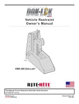
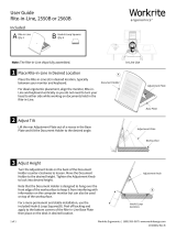
VBR-600 Dok-Lok®
Vehicle Restraint
Owner’s Manual
This Manual Covers Restraints Built After Serial Numbers:
4634330001 and up
PRINTED IN U.S.A.
RITE-HITE PRINT SHOP
PUBLICATION NO. 1328
JANUARY 2016
MADE IN U.S.A.

2Pub. No. 1328 — January 2016
RITE-HITE®VBR-600 DOK-LOK®Owner’s Manual

Pub. No. 1328 — January 2016 3
RITE-HITE®VBR-600 DOK-LOK®Owner’s Manual
INTRODUCTION . . . . . . . . . . . . . . . . . . . . . . . . . . . . . . . . . . . . . . . . . . . . . . . . . . . . . . . . . . . . . . . . . . . . . . . . . . . . . . . . . . . . . . . . . . . . . . . 3
SAFETY WARNINGS . . . . . . . . . . . . . . . . . . . . . . . . . . . . . . . . . . . . . . . . . . . . . . . . . . . . . . . . . . . . . . . . . . . . . . . . . . . . . . . . . . . . . . . . . . . . . 4
FCC COMPLIANCE . . . . . . . . . . . . . . . . . . . . . . . . . . . . . . . . . . . . . . . . . . . . . . . . . . . . . . . . . . . . . . . . . . . . . . . . . . . . . . . . . . . . . . . . . . . . . . . . 5
OWNERS RESPONSIBILITY . . . . . . . . . . . . . . . . . . . . . . . . . . . . . . . . . . . . . . . . . . . . . . . . . . . . . . . . . . . . . . . . . . . . . . . . . . . . . . . . . . . . . . . 6
DEFINITION AND FUNCTION . . . . . . . . . . . . . . . . . . . . . . . . . . . . . . . . . . . . . . . . . . . . . . . . . . . . . . . . . . . . . . . . . . . . . . . . . . . . . . . . . . . . . . . 7
FEATURES . . . . . . . . . . . . . . . . . . . . . . . . . . . . . . . . . . . . . . . . . . . . . . . . . . . . . . . . . . . . . . . . . . . . . . . . . . . . . . . . . . . . . . . . . . . . . . . . . . . . . 8
OPERATING PROCEDURE . . . . . . . . . . . . . . . . . . . . . . . . . . . . . . . . . . . . . . . . . . . . . . . . . . . . . . . . . . . . . . . . . . . . . . . . . . . . . . . . . . . . . . . . 10
MAINTENANCE . . . . . . . . . . . . . . . . . . . . . . . . . . . . . . . . . . . . . . . . . . . . . . . . . . . . . . . . . . . . . . . . . . . . . . . . . . . . . . . . . . . . . . . . . . . . . . . . . . 14
TROUBLESHOOTING . . . . . . . . . . . . . . . . . . . . . . . . . . . . . . . . . . . . . . . . . . . . . . . . . . . . . . . . . . . . . . . . . . . . . . . . . . . . . . . . . . . . . . . . . . . . 15
REPLACEMENT PARTS. . . . . . . . . . . . . . . . . . . . . . . . . . . . . . . . . . . . . . . . . . . . . . . . . . . . . . . . . . . . . . . . . . . . . . . . . . . . . . . . . . . . . . . . . . . . 25
WARRANTY . . . . . . . . . . . . . . . . . . . . . . . . . . . . . . . . . . . . . . . . . . . . . . . . . . . . . . . . . . . . . . . . . . . . . . . . . . . . . . . . . . . . . . . . . . . BACK COVER
INTRODUCTION
Read and understand this manual before attempting to install or operate any DOK-LOK vehicle restraint. For best results, have this product
serviced by your authorized Rite-Hite®representative. The VBR-600 DOK-LOK vehicle restraint by Rite-Hite®is intended to provide a safer
workplace for workers in shipping and receiving dock areas. The VBR-600 DOK-LOK vehicle restraint is a hydraulic restraint device that, when
properly installed and operated, retains a secure connection between the truck and dock. Signal lights and signs provide instructions to the truck
driver and DOK-LOK vehicle restraint operator that a safe condition exists. The DOK-LOK vehicle restriant is operated by pressing push buttons
on an inside control panel.
TABLE OF CONTENTS
PRODUCT SPECIFIC WARRANTY
Rite-Hite®warrants the VBR-600 DOK-LOK vehicle restraint for two-years parts and labor from date of shipment in accordance with Rite-
Hite's Standard Warranty Policy.
NOTICE TO USER
Your local Rite-Hite®representative provides a Planned Maintenance Program (P.M.P.) which can be fitted to your specific operation. Call
your local representative or Rite-Hite®at 414-355-2600.
The Rite-Hite products in this manual are covered by one or more of the following U.S. patents: 5882167, 6065172, 6070283, 6085375,
6092970, 6106212, 6116839, 6190109, 6276016, 6311352, 6318947, 6322310, 6360394, 6368043, 6431819, 6488464, 6524053, 6726432,
6773221, 6832403, 6880301, 7032267, 7062814, 7213285, 7216391, 7363670, 7380305, 7503089, 7533431, 7546655, 7584517, 7681271,
7823239, 7841823, 7877831, 7914042, 8006811, 8065770, 8141189, 8191194, 8286757, 8287223, 8303235, 8307956, 8443474, 8464384,
8464846, 8465245, 8497761, 8499897, 8544130, 8547234, 8590087, 8590673, 8616826, 8657551, 8662535, 8678736, 8690087, 8905198,
9010501, 9096170, 9096397, 9126775, 9139384, 9145273, 9150367, 9174811, 9227799, 9230419 and pending U.S and foreign patent
applications. RITE-HITE®, THINMANTM, SAFE-T-LIP®, HYDRACHEK®, WHEEL-LOKTM, DOK-LOK®, DUAL-DOK®, SAFE-T-STRUTTM,
DOK-COMMANDER®, JUMBOTM, HYDRA-RITETM, SAFE-T-GATE®, RITE-VUTM LIGHT COMMUNICATION SYSTEM and SMOOTH TRANSITION
DOK SYSTEMTM, are trademarks of Rite-Hite®.

4Pub. No. 1328 — January 2016
RITE-HITE®VBR-600 DOK-LOK®Owner’s Manual
SAFETY WARNINGS
DO NOT
OPERATE
LOCKOUT/TAGOUT PROCEDURES
The Occupational Safety and Health Administration requires that, in addition to posting safety warnings and barricading the work area, the
power supply has been locked in the OFF position or disconnected. It is mandatory that an approved lockout device is utilized. An example of
a lockout device is illustrated. The proper lockout procedure requires that the person responsible for the repairs is the only person who has
the ability to remove the lockout device.
In addition to the lockout device, it is also a requirement to tag the power control in a manner that will clearly note that repairs are under way
and state who is responsible for the lockout condition. Tagout devices have to be constructed and printed so that exposure to weather
conditions or wet and damp locations will not cause the tag to deteriorate or become unreadable.
Rite-Hite Corporation does not recommend any particular lockout device, but recommends the utilization of an OSHA approved device (refer
to OSHA regulation 1910.147). Rite-Hite Corporation also recommends the review and implementation of an entire safety program for the
Control of Hazardous Energy (Lockout/Tagout). These regulations are available through OSHA publication 3120.
This is the highest level statement. Failure to follow the
listed instructions will most likely result in severe injury or
death.
IMPORTANT is used to draw attention
to a procedure that needs to be followed to prevent
machine or property damage.
When working with electrical or electronic controls, make
sure that the power source has been locked out and
tagged according to OSHA regulations and approved local
electrical codes.
This is a statement of serious hazard. Failure to follow the
listed instructions could place the individual at risk of
serious injury or death.
The statements used with this level of
warning deal with a safe operating
procedure. If the procedure is ignored, the possibility of
personal injury may exist.
FIGURE 1 - LOCKOUT/TAGOUT

FCC COMPLIANCE
NOTE:
This equipment has been tested and found to comply with the limits
for a Class A digital device, pursuant to Part 15 of the FCC Rules.
These limits are designed to provide reasonable protection against
harmful interference when the equipment is operated in a commercial
environment. This equipment generates, uses , and can radiate radio
frequency energy and, if not installed and used in accordance with the
instruction manual, may cause harmful interference to radio
communications. Operation of this equipment in a residential area is
likely to cause harmful interference in which case the user will be
required to correct the interference at his or her own expense.
NOTE:
Changes or modifications not expressly approved by the party
responsible for compliance could void the user’s authority to operate
the equipment.
This device complies with Part 15 of the FCC Rules. Operation is
subject to the following to conditions: (1) This device may not cause
harmful interference, and (2) this device must accept any interference
received, including interference that may cause undesirable operation.
Pub. No. 1328 — January 2016 5
RITE-HITE®VBR-600 DOK-LOK®Owner’s Manual
FCC COMPLIANCE

6Pub. No. 1328 — January 2016
RITE-HITE®VBR-600 DOK-LOK®Owner’s Manual
OWNER RESPONSIBILITY
1. The owner should recognize the inherent danger of the
interface between dock and transport vehicle. The owner
should, therefore, train and instruct operators in the safe use
of dock equipment in accordance with the information provided
below. The manufacturer shall publish, provide to the initial
purchaser, and make the following information readily available
to owners:
•Installation instructions
•Recommended initial and periodic inspections procedures
•Maintenance procedures
•Operating instructions
•Descriptions or specifications for replaceable or repairable
parts
•Tables identifying the grade (slope) for all variations of
length or configuration of the dock equipment, and
•Information identifying the maximum uncontrolled drop
encountered upon sudden removal of support while within
the working range of the equipment.
It shall be the responsibility of the owner to verify that the
material listed in this section has been received and that it is
made available for the instruction and training of presonnel
entrusted with the use or maintenance of the dock equipment.
2. When a transport vehicle is parked at a loading dock, it is
important that the vehicle is relatively perpendicular to the
dock face and in close contact with at least one of the dock
bumpers.
3. Nameplates, cautions, instructions, and posted warnings shall
not be obscured from the view of operating or maintenance
personnel for whom such warnings are intended.
4. Manufacturer’s recommended periodic maintenance and
inspection procedures in effect at date of shipment shall be
followed, and written records of the performance of these
procedures should be kept.
5. As with any piece of machinery, dock equipment requires routine
maintenance, lubrication, and adjustments. Your local
RITE-HITE®representative offers owners the option of a
Planned Maintenance Program (P.M.P.). As part of this service,
your local RITE-HITE®representative will do all routine
maintenance, lubrication, and adjustments.
6. Dock equipment that is structurally damaged shall be removed
from service, inspected by a manufacturer’s authorized
representative, and repaired as needed before being placed
back in service.
7. The manufacturer shall make available replacement
nameplates, caution/instruction labels, and
operating/maintenance manuals upon request of the owner.
The owner shall see that all nameplates, caution/instruction
markings or labels are in place and legible, and that the
appropriate operating/maintenance manuals are provided to
users.
8. Modifications or alterations of dock equipment shall be made
only with written permission of the original manufacturer.
These changes shall also satisfy all safety recommendations
of the original equipment manufacturer for the particular
application of the dock equipment.
9. In order to be entitled to the benefits of the standard product
warranty, the dock equipment must have been properly
installed, maintained and operated within its rated capacities
and/or specific design parameters, and not otherwise abused.
10. It is recommended that trailers equipped with air ride
suspensions should remove the air from the suspension to
minimize trailer bed drop, prior to loading or unloading.
11. When industrial trucks are driven on and off transport vehicles
during the loading and unloading operation, the brakes on the
transport vehicle shall be applied and wheel chocks or a
positive restraining device shall be engaged.
12. In selecting dock equipment, it is important to consider not
only present requirements but also future plans or adverse
environments.

Pub. No. 1328 — January 2016 7
RITE-HITE®VBR-600 DOK-LOK®Owner’s Manual
DEFINITION AND FUNCTION
The VBR-600 DOK-LOK vehicle restraint is a hydraulic, pit stored
restraint device used to secure trucks and semi-trailers with an intact
Rear Impact Guard (R.I.G.) to the face of a loading dock. This is
achieved by securing the R.I.G. with a steel barrier. This prevents
forward movement of the truck/trailer that may create an unsafe void
between the face of the dock and the rear end of the truck/trailer as
a forklift travels from the loading dock onto the trailer; or to create an
obstruction noticeable to the truck driver, should the driver
accidentally try to pull the truck/trailer away while it is being serviced.
The proper or improper activation of the barrier is monitored by:
• VISUAL CONTROL
— One set of flashing green or red lights located at the inside
of the building for the forklift operator, and one set located
outside of the building for the truck driver. In addition to the
lights, there are three instruction signs.
• AUDIO CONTROL
— A horn will sound at the inside of the building, warning the
forklift operator if there is not R.I.G. present, or if the
engagement is improper. In this case, the trailer must be
secured by other means (wheel chokes, etc.) prior to servicing
trailer.
Prerequisite for proper barrier engagement is that the trailer is
parked firmly against a 4" (trade standard) thick dock bumper. The
activation/deactivation is solely controlled from inside of the building
by momentarily depressing either the Lock (raise) button or the
Unlock (lower) button.
The normal mode of the barrier is in the lower STORED
position, showing a flashing red light (trailer not secured) at the
inside of the building and a flashing green light (trailer free to move
to or away from the loading dock) at the outside of the building.
Once the trailer is parked, the dock attendant will depress the Lock
button. This will raise the barrier to engage the R.I.G. As soon as the
R.I.G. is properly locked, there will be a simultaneous light change -
the inside will change from red to green flashing (trailer secured) and
the outside will change from green to red flashing (do not move
trailer). After the service is complete, the dock attendant will have to
depress the Unlock button which then will return the barrier to its
STORED position.
A proper barrier engagement is achieved when the barrier raises
unobstructed to secure the horizontal cross member of the R.I.G.
Assembly. An improper barrier engagement is if the horizontal cross
member of the R.I.G. is missing, obstructed or it is bent or located
so far toward the rear axle of the trailer that it will prevent the free
passage of the barrier. At this point, the trailer must be secured by
other means (example: wheel chocks) in order to become
serviceable.

8Pub. No. 1328 — January 2016
RITE-HITE®VBR-600 DOK-LOK®Owner’s Manual
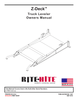
Refer to Figure 2, page 8 for the locations of the following features:
R.I.G.
Acronym used for the Federally mandated rear impact
guard located on the rear of over the road trailers to
prevent accidental underride by automobiles.
POSITIONING CYLINDER/LIFTING SPRING
Positioning Cylinder extends to lower main cylinder/barrier assembly
to stored state. Lifting Spring, raises locking cylinder/barrier
assembly to capture R.I.G. and keep in constant contact.
MAIN CYLINDER / RETURN SPRINGS
Main Cylinder extends to position barrier outside of pit. Return
springs retract the main cylinder, keeping the vertical barrier face in
contact with the R.I.G.
R.I.G. SENSOR / LOCK LIMIT SWITCH
Detects when the barrier is secured to the R.I.G.
BARRIER ASSEMBLY
Secures R.I.G. to prevent trailer from separating from the dock.
STORED LIMIT SWITCH
Senses the barrier assembly is in the proper stored position.
HYDRAULIC VALVE BLOCK
Allows restraint to operate using the leveler power unit.
PIT COVER/BRUSH SEAL
Protects the barrier assembly, float mechanism, hydraulic hoses and
cylinders from debris.
CONTROL BOX, OUTSIDE LIGHT BOX AND SIGNAGE
Combination of these components is used to control the VBR-600
DOK-LOK vehicle restraint and provide audio/visual communications
to the dock attendant and trailer driver.
MOUNTING INSERT
VBR6 is assembled to this and installed into mounting pan. May ship
together with mounting pan or seperately.
MOUNTING PAN
Forms VBR6 pit. Placed in leveler pit and building wall. Prior to
pouring concrete pit floor, VBR6 is installed in mounting pan by way
of the mounting insert. May ship together with mounting insert or
earlier. To be poured in to building prior to VBR6 shipment.
FEATURES

Pub. No. 1328 — January 2016 9
RITE-HITE®VBR-600 DOK-LOK®Owner’s Manual
outside
signs
inside
sign
light
box
control
box
main cylinder
return springs
main
cylinder
R.I.G. sensor
lock limit
switch
barrier
assembly
lifting
spring
positioning
cylinder
brush
seal
stored
limit switch
mounting
pan
valve
block
mounting
insert
FIGURE 2 - VBR-600 DOK-LOK VEHICLE RESTRAINT FEATURES

10 Pub. No. 1328 — January 2016
RITE-HITE®VBR-600 DOK-LOK®Owner’s Manual
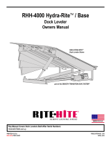
OPERATING PROCEDURE
Stored Position / Restraint UNLOCKED
Barrier is in the STORED position. Inside light is flashing red alerting
forklift operator unsafe condition exists. Outside light is flashing green
alerting truck driver it is safe to back in.
OUTSIDE LIGHT
STATUS
CONTROL BOX
STATUS
RESTRAINT POSITION
RED
GREEN
INSIDE LIGHTS OUTSIDE LIGHTS
OUTSIDE LIGHTS
Check outside lights when
both LEDs are o.
UNLOCK
LOCK
1
3
2
HORN OVERRIDE
DOK-LOK®
DO NOT ENTER TRAILER
ENTER TRAILER
Visually inspect before loading/
unloading vehicle. DOK-LOK
hook must secure rear impact
guard. See warnings on side
panel.
Additional warning labels,
manuals and other information
are available by calling:
1-800-456-0600
If red light is on and/or horn
sounds, DOK-LOK is not
properly engaged.
Check operation of DOK-LOK.
Vehicle may not be against dock.
R.I.G. may not be compatible.
Hook travel may be obstructed.
Before using "HORN OVERRIDE,"
secure vehicle by other means.
Reset system by engaging "HORN
OVERRIDE" control again. Then repeat
"UNLOCK
" operation.
When in "HORN OVERRIDE" mode:
Both red and green Lights flash. "LOCK" and
"UNLOCK" controls are not functional.
Horn can be silenced by engaging
"HORN OVERRIDE" control.
Before using "HORN OVERRIDE," secure
vehicle by other means prior to entering.
If horn and red light are on
after "UNLOCK" control is
pressed, hook may be held
by R.I.G.
To release hook:
Back trailer up against dock.
Repeat "UNLOCK" operation.
FIGURE 3 - STORED POSITION
• Before loading or unloading a vehicle at
your loading dock while using a DOK-LOK
vehicle restraint, always visually inspect to
be sure that the barrier blocks the R.I.G.
assembly. If a condition occurs that cannot
be remedied by backing the trailer firmly
against the dock bumpers, secure the trailer
by other means.
• Be sure that the area around the R.I.G.
assembly is free of plates or other
obstructions.
• Always operate the DOK-LOK vehicle
restraint from the top of the dock.
• Inspect all restraint lights daily to make
certain they work properly.
• Perform maintenance on restraints in
accordance with Maintenance on page 19 of t h i s
manual.
• DOK-LOK vehicle restraints should be
operated only by authorized personnel who have
read and understand the Owner’s
Manual.
• Call your local representative or Rite-Hite
at (800) 456-0600 with any questions.
FAILURE TO FOLLOW THESE PROCEDURES COULD
ALLOW UNEXPECTED TRAILER / LOADING DOCK
SEPERATION RESULTING IN DEATH OR SERIOUS INJURY!

Pub. No. 1328 — January 2016 11
RITE-HITE®VBR-600 DOK-LOK®Owner’s Manual
Restraint LOCKED
Once the R.I.G. is obstructed by the barrier, a LOCKED
condition exists. Inside light is flashing green alerting the forklift
operator a safe condition exists. Outside light is flashing red alerting
truck driver not to move.
OUTSIDE LIGHT
STATUS
CONTROL BOX
STATUS
RESTRAINT POSITION
OUTSIDE LIGHTS
INSIDE LIGHTS
GREEN
RED
OUTSIDE LIGHTS
Check outside lights when
both LEDs are o.
UNLOCK
LOCK
1
3
2
HORN OVERRIDE
DOK-LOK®
DO NOT ENTER TRAILER
ENTER TRAILER
Visually inspect before loading/
unloading vehicle. DOK-LOK
hook must secure rear impact
guard. See warnings on side
panel.
Additional warning labels,
manuals and other information
are available by calling:
1-800-456-0600
If red light is on and/or horn
sounds, DOK-LOK is not
properly engaged.
Check operation of DOK-LOK.
Vehicle may not be against dock.
R.I.G. may not be compatible.
Hook travel may be obstructed.
Before using "HORN OVERRIDE,"
secure vehicle by other means.
Reset system by engaging "HORN
OVERRIDE" control again. Then repeat
"UNLOCK
" operation.
When in "HORN OVERRIDE" mode:
Both red and green Lights flash. "LOCK" and
"UNLOCK" controls are not functional.
Horn can be silenced by engaging
"HORN OVERRIDE" control.
Before using "HORN OVERRIDE," secure
vehicle by other means prior to entering.
If horn and red light are on
after "UNLOCK" control is
pressed, hook may be held
by R.I.G.
To release hook:
Back trailer up against dock.
Repeat "UNLOCK" operation.
FIGURE 4 - RESTRAINT LOCKING
OUTSIDE LIGHT
STATUS
CONTROL BOX
STATUS
RESTRAINT POSITION
OUTSIDE LIGHTS
INSIDE LIGHTS
GREEN
RED
OUTSIDE LIGHTS
Check outside lights when
both LEDs are o.
UNLOCK
LOCK
1
3
2
HORN OVERRIDE
DOK-LOK®
DO NOT ENTER TRAILER
ENTER TRAILER
Visually inspect before loading/
unloading vehicle. DOK-LOK
hook must secure rear impact
guard. See warnings on side
panel.
Additional warning labels,
manuals and other information
are available by calling:
1-800-456-0600
If red light is on and/or horn
sounds, DOK-LOK is not
properly engaged.
Check operation of DOK-LOK.
Vehicle may not be against dock.
R.I.G. may not be compatible.
Hook travel may be obstructed.
Before using "HORN OVERRIDE,"
secure vehicle by other means.
Reset system by engaging "HORN
OVERRIDE" control again. Then repeat
"UNLOCK
" operation.
When in "HORN OVERRIDE" mode:
Both red and green Lights flash. "LOCK" and
"UNLOCK" controls are not functional.
Horn can be silenced by engaging
"HORN OVERRIDE" control.
Before using "HORN OVERRIDE," secure
vehicle by other means prior to entering.
If horn and red light are on
after "UNLOCK" control is
pressed, hook may be held
by R.I.G.
To release hook:
Back trailer up against dock.
Repeat "UNLOCK" operation.
FIGURE 5 - RESTRAINT LOCKED
Visually inspect to ensure that the DOK-LOK barrier
obstructs the R.I.G. of the trailer being serviced before
operating the dock leveler.
Restraint Locking, LOCK Button Pressed
Trailer has backed into loading dock and is parked firmly against
dock bumpers. Barrier extends out of the pit from stored position
and moves up to obstruct R.I.G. Inside light is steady red alerting
the operator that an unsafe condition exists and barrier is in transit.
Outside light is flashing red alerting truck driver not to move.
If horn sounds, go to FAULT state, otherwise go to Restraint
LOCKED.
If trailer can not be restrainted due to a lift gate or other
obstruction that could become damaged, go to OVERRIDE
state.

12 Pub. No. 1328 — January 2016
RITE-HITE®VBR-600 DOK-LOK®Owner’s Manual
Restraint UNLOCKING, UNLOCK Button Pressed
Barrier extends and moves down from the LOCKED position. Once
down the barrier retracts to the STORED position under the leveler.
Inside light is steady red alerting the operator that an unsafe
condition exists and
barrier is in transit. Outside light is flashing red alerting truck driver
not to move.
If horn sounds go to FAULT state, otherwise go to STORED.
FAULT State From LOCKING State
Barrier cannot obstruct the R.I.G. Barrier will auto-retract to its
stored position. This could be due to a R.I.G. that is located too far
toward the rear axle, bent, obstructed or missing. Inside light is
flashing red and horn is pulsing, alerting the forklift operator that the
trailer is not locked. Outside light is flashing red alerting the truck
driver not to move.
If the trailer is parked firmly against the dock bumpers go to
OVERRIDE state. If not, press UNLOCK to clear the fault, have
trailer back up and repeat Restraint LOCKING.
FAULT State From UNLOCKING State
Barrier cannot retract to the STORED position. The barrier could be
caught on the R.I.G. or another part of the trailer. Inside light is
flashing red and horn is pulsing, alerting the forklift operator that the
trailer is not locked. Outside light is flashing red alerting the truck
driver not to move.
Make sure trailer is parked firmly against the dock bumpers. If not,
press LOCK to entrap R.I.G., have trailer back up and repeat
Restraint UNLOCKING.
OUTSIDE LIGHT
STATUS
CONTROL BOX
STATUS
RESTRAINT POSITION
RED
GREEN
INSIDE LIGHTS OUTSIDE LIGHTS
OUTSIDE LIGHTS
Check outside lights when
both LEDs are o.
UNLOCK
LOCK
1
3
2
HORN OVERRIDE
DOK-LOK®
DO NOT ENTER TRAILER
ENTER TRAILER
Visually inspect before loading/
unloading vehicle. DOK-LOK
hook must secure rear impact
guard. See warnings on side
panel.
Additional warning labels,
manuals and other information
are available by calling:
1-800-456-0600
If red light is on and/or horn
sounds, DOK-LOK is not
properly engaged.
Check operation of DOK-LOK.
Vehicle may not be against dock.
R.I.G. may not be compatible.
Hook travel may be obstructed.
Before using "HORN OVERRIDE,"
secure vehicle by other means.
Reset system by engaging "HORN
OVERRIDE" control again. Then repeat
"UNLOCK
" operation.
When in "HORN OVERRIDE" mode:
Both red and green Lights flash. "LOCK" and
"UNLOCK" controls are not functional.
Horn can be silenced by engaging
"HORN OVERRIDE" control.
Before using "HORN OVERRIDE," secure
vehicle by other means prior to entering.
If horn and red light are on
after "UNLOCK" control is
pressed, hook may be held
by R.I.G.
To release hook:
Back trailer up against dock.
Repeat "UNLOCK" operation.
FIGURE 6 - RESTRAINT UNLOCKING
OUTSIDE LIGHT
STATUS
CONTROL BOX
STATUS
RESTRAINT POSITION
HORN
RED
GREEN
INSIDE LIGHTS OUTSIDE LIGHTS
OUTSIDE LIGHTS
Check outside lights when
both LEDs are o.
UNLOCK
LOCK
1
3
2
HORN OVERRIDE
DOK-LOK®
DO NOT ENTER TRAILER
ENTER TRAILER
Visually inspect before loading/
unloading vehicle. DOK-LOK
hook must secure rear impact
guard. See warnings on side
panel.
Additional warning labels,
manuals and other information
are available by calling:
1-800-456-0600
If red light is on and/or horn
sounds, DOK-LOK is not
properly engaged.
Check operation of DOK-LOK.
Vehicle may not be against dock.
R.I.G. may not be compatible.
Hook travel may be obstructed.
Before using "HORN OVERRIDE,"
secure vehicle by other means.
Reset system by engaging "HORN
OVERRIDE" control again. Then repeat
"UNLOCK
" operation.
When in "HORN OVERRIDE" mode:
Both red and green Lights flash. "LOCK" and
"UNLOCK" controls are not functional.
Horn can be silenced by engaging
"HORN OVERRIDE" control.
Before using "HORN OVERRIDE," secure
vehicle by other means prior to entering.
If horn and red light are on
after "UNLOCK" control is
pressed, hook may be held
by R.I.G.
To release hook:
Back trailer up against dock.
Repeat "UNLOCK" operation.
FIGURE 7 - FAULT STATE

Pub. No. 1328 — January 2016 13
RITE-HITE®VBR-600 DOK-LOK®Owner’s Manual
OVERRIDE State, OVERRIDE Code Entered after
Securing Trailer by Alternate Means
An alternate means of securing the truck must be used if the barrier
can not capture the rear impact guard. (i.e. wheel chocks). Inside
lights are flashing red and green alerting the forklift operator the
trailer is secured by other means. Outside light is flashing red
alerting the truck driver not to move.
To return to STORED, press the HORN OVERRIDE button followed
by the UNLOCK button.
OUTSIDE LIGHT
STATUS
CONTROL BOX
STATUS
RESTRAINT POSITION
OUTSIDE LIGHTS
INSIDE LIGHTS
RED
GREEN
OUTSIDE LIGHTS
Check outside lights when
both LEDs are o.
UNLOCK
LOCK
1
3
2
HORN OVERRIDE
DOK-LOK®
DO NOT ENTER TRAILER
ENTER TRAILER
Visually inspect before loading/
unloading vehicle. DOK-LOK
hook must secure rear impact
guard. See warnings on side
panel.
Additional warning labels,
manuals and other information
are available by calling:
1-800-456-0600
If red light is on and/or horn
sounds, DOK-LOK is not
properly engaged.
Check operation of DOK-LOK.
Vehicle may not be against dock.
R.I.G. may not be compatible.
Hook travel may be obstructed.
Before using "HORN OVERRIDE,"
secure vehicle by other means.
Reset system by engaging "HORN
OVERRIDE" control again. Then repeat
"UNLOCK
" operation.
When in "HORN OVERRIDE" mode:
Both red and green Lights flash. "LOCK" and
"UNLOCK" controls are not functional.
Horn can be silenced by engaging
"HORN OVERRIDE" control.
Before using "HORN OVERRIDE," secure
vehicle by other means prior to entering.
If horn and red light are on
after "UNLOCK" control is
pressed, hook may be held
by R.I.G.
To release hook:
Back trailer up against dock.
Repeat "UNLOCK" operation.
FIGURE 8 - HORN OVERRIDE STATE

14 Pub. No. 1328 — January 2016
RITE-HITE®VBR-600 DOK-LOK®Owner’s Manual
NOTE: If a leveler is installed at the VBR-600 DOK-
LOK vehicle restraint location, it may be
necessary to raise the leveler before performing maintenance.
Raise the leveler, insert and secure the
SAFE-T-STRUT, and LOCKOUT/
TAGOUT the power source.
NOTE: Your local Rite-Hite representative provides a
Planned Maintenance Program (P.M.P.) which
can be fitted to your specific operation. Call
your local representative.
DAILY
1. Remove debris around the VBR-600 DOK-LOK vehicle restraint
pit and from loading dock face.
2. Verify inside and outside lights are working.
3. Replace damaged or missing light bulbs and lenses.
4. Repair, remount, or replace outside and inside signs as
required.
5. Inspect dock bumpers. Missing bumpers must be replaced.
180 DAYS
1. Perform all Daily maintenance.
2. Inspect hydraulic hoses and power unit.
3 Check oil fluid level.
4. Inspect pit junction and light box. They should be rigidly
mounted. If loose or damaged, inspect all wires and wire
connections.
5. Inspect switch wires from VBR-600 DOK-LOK vehicle restraint
to junction box. Look for kinks, crushed areas, etc.
6. Perform operational test after all maintenance repairs and
adjustments are complete.
7. Inspect dock bumpers. Four inches (4") of protection is required.
Worn, torn, loose or missing bumpers must be replaced.
MAINTENANCE
A safe work place requires all lights and the horn to be
working properly. DO NOT use DOK-LOK vehicle restraint if
parts are broken or missing.
When working with electrical or electronic controls, make
sure that the power source has been locked out and tagged
according to OSHA regulations and approved local
electrical codes.
Post safety warnings and barricade work area, at dock level
and at ground level, to prevent unauthorized use of the
dock pition.
Maintenance may be required more frequently at loading
docks exposed to harsh environments (extreme climates,
corrosive chemicals, frequency of usage, etc.). Consult
Rite-Hite if these conditions exist for accelerated
maintenance requirements.

Pub. No. 1328 — January 2016 15
RITE-HITE®VBR-600 DOK-LOK®Owner’s Manual
Problem Probable Cause Solution
1 DOK-LOK barrier does not raise and Power source malfunction. Check power source including building
lights do not flash. circuit breaker, 1A fuse and 15A fuse on
power board.
2 DOK-LOK lights are flashing, but Blown fuse. Check 15A fuse on power board.
barrier does not raise/lower, to full Replace as required.
extent. Low incoming voltage. Verify incoming voltage at L1 and L2 is
a minimum of 110V.
Power module failure. Verify the appropriate LED is lit when
the LOCK button or UNLOCK button is
pressed.
No push button inputs. Check for failed push button board
or disconnect ribbon cable.
Hydraulic power unit Check hydraulic power unit. Repair or
replace as required.
3 DOK-LOK barrier is operational but all Bulbs burnt out, loose or Check all bulbs and replace as
lights are out. missing. required.
Damaged CPU module. If the ISG and OSR LEDs are not
flashing while in the LOCKED position
or the ISR and OSG LEDs are not
flashing while in the UNLOCKED
position, replace the CPU module as
required.
Incorrect or damaged field Verify wiring per Electrical Schematic.
wiring.
4 DOK-LOK horn does not sound, but Horn failure. Power horn using 12V DC power. If
lights and barrier are operational. horn does not sound, replace as
required.
Damaged CPU module. LED labeled HORN should be flashing
while in FAULT state. If not, replace
CPU module as required.
Incorrect or damaged field Verify wiring per Electrical Schematic.
wiring.
TROUBLESHOOTING
GENERAL DIAGNOSTIC INFORMATION

16 Pub. No. 1328 — January 2016
RITE-HITE®VBR-600 DOK-LOK®Owner’s Manual
Sensing Switch Test Procedure
1. Set multimeter to “RX1” scale for “Continuity Test”.
2. Attach multimeter leads to white and black wires of mag. reed
switch connector. You should have:
— no magnet present — no meter reading. —
magent present — a “Full Scale” meter reading.
white
black
FIGURE 9 - SENSING SWITCH TEST AND SWITCH/BARRIER POSITION CHART
SWITCH TESTING

Pub. No. 1328 — January 2016 17
RITE-HITE®VBR-600 DOK-LOK®Owner’s Manual
LED STATUS CHART
VBR-600
VERTICAL BARRIER RESTRAIN
T
DOK-LOK LIMIT SWITCH 1 [SW1]
DOK-LOK LIMIT SWITCH 2 [SW2]
UNLOCK INTERLOCK [UNLK ITL]
LOCK PUSH BUTTON
UNLOCK PUSH BUTTON
HORN SILENCE PUSH BUTTONS (1/2/3)
INSIDE RED LIGHT [ISR]
INSIDE GREEN LIGHT [ISG]
CORNER-VU RED LIGHT [CVU RD]
CORNER-VU GREEN LIGHT [CVU GRN]
LEVELER-VU RED LIGHT [LVU RD]
LEVELER-VU GREEN LIGHT [L-VU GRN]
OUTSIDE RED LIGHT [OSR]
OUTSIDE GREEN LIGHT [OSG]
DOK-LOK HORN [HORN]
LEVELER MOTOR CONTACTOR
[COMBINED POWER UNIT ONLY]
RESTRAINT OVERLOAD LED [YELLOW]
K1 - GREEN LIGHT INTERLOCK
K2 - SECURITY SYSTEM INTERFACE
[IF EQUIPPED]
K2 - COMBINED POWER UNIT
[IF EQUIPPED]
MOTOR OUPTUT #1 [M1/RUN]
SOLENOID #1 (RSOL1 / EXTEND)
SOLENOID #2 (RSOL2 / FLOAT)
SOLENOID #3 (RSOL3 / DIVERT)
[COMBINED POWER UNIT ONLY]
12VDC POWER SUPPLY OK
TERMINAL BLOCK NO. J13.1 J13.2 J14.2 MEMBRANE J7.15 J7.16 J12.1 J12.2 J12.3 J12.4 J11.2 J11.1 J7.18 J15.1 N/A J9.3 J10.3 J10.3 J5.4 J7.3 J7.2 J7.1 J2.1-6
POWER BOARD LEDs --------------------LD2LD10LD9LD8LD7
MICRO CONTROL BOARD LEDs LD20 LD23 LD30 LD52 LD17 LD19 LD11 LD13 LD18 LD12 LD49 LD48 LD15 LD42 LD50 LD9 LD10 LD10 LD1 LD8 LD6 LD2 -
01.01.00 LOCKED STATE TF? - - -FPFPFPPFFFFTTFFFTFT
01.01.01 LOCKING SEQUENCE EXTEND FF?M- -TFPFPFPFFTFFTTTFFTT
01.01.05 LOCKING SEQUENCE RAISE FF? - - - TFPFPFPFFTFFTTTFTTT
01.01.06 LOCKING SEQUENCE RETRACT FF? - - - TFPFPFPFFFFFTFFFTTT
01.02.00 UNLOCKED STATE FT?- - -PFPFPFFPFFFFTFFFFFT
01.02.01 UNLOCKING SEQUENCE EXTEND TFITL-M-TFPFPFPFFTFFTTTFFTT
01.02.06 UNLOCKING SEQUENCE LOWER FFITL- - -TFPFPFPFFTFFTTTTFTT
01.02.07 UNLOCKING SEQUENCE RETRACT FFITL- - -TFPFPFPFFFFFTFFFFFT
01.04.00 FAULT STATE ???- - -PFPFPFPFPFFFFFFFFFT
01.04.01 FAULT SILENCED STATE FFT
T
FFFFP
M
-
-
?
?
?FFFT
01.11.00 OVERLOAD FAULT STATE ???- - -PFPFPFPFKFTFFFFFFFT
NO. STATE / SEQUENCE NO.
KEY
? - VARYS DEPENDING ON OPERATION K - CONTINUOUS CHIRP
DES
S
ER
P
NOT
T
UB NEHW STHGIL - MGNIT
ANRE
T
L
A -
A
SE
HC
TIWS
PI
D
GNISU
YD
AE
TS
OT
TES[
GNI
HSA
L
F /
G
N
IS
L
UP
-
P
FFO - F ]
NO
YD
AE
TS
-
TNO
TUPNI
K
CO
L
R
E
TNI - LT
I
MOTOR OVERLOAD RESET PROCEDURE
If Yellow LED LD50 is illuminated and the Dok-Lok Horn is Chirping, system is in an Overload Fault State.
To reset the motor overload:
1) Press and Horn Silence #2 Buon unl Horn Chirps (Approximately 5 Seconds). O
R
2) Press and Release Restraint O/L Buon on Micro Controller Board
.
When the motor overload has been reset, the Yellow LD50 LED will turn off and normal operaon resumes
.
If Dok-Lok motor sll does not run aer reseng the overload, check Motor Fuse 10FU1
.
AAA
POWER BOARD
OUTPUTS
115/230VAC
INPUTS
FIELD PUSH BUTTONS
MICRO CONTROL BOARD
RELAY12VDC
OUTPUTS

18 Pub. No. 1328 — January 2016
RITE-HITE®VBR-600 DOK-LOK®Owner’s Manual
SETTING HORN OVERRIDE CODE
1. *Press and hold DIAGNOSTIC button until the horn chirps
(approximately five seconds).
2. Enter the factory preset HORN OVERRIDE code: 1223. (horn
will chirp)
3. Enter the new HORN OVERRIDE code. The code can be one
to four numbers in length.
4. Once the new code has been entered, press the LOCK button.
5. Controls reset with new HORN OVERRIDE code enabled.
If code has been forgotten, follow the above procedure and
enter a new code.
*NOTE: To change code or enter diagnostic modes without
opening the control box cover, press and hold the “1” and “3”
buttons on the cover until the horn chirps.
ENTER HYDRAULIC FILL MODE
1. *Press and hold DIAGNOSTIC button until the horn chirps
(approximately 5 seconds).
2. *Press the HORN OVERRIDE #2 button (horn will chirp).
3. *System is now in FILL MODE. Press and hold the LOCK and
UNLOCK buttons to run the unit Up or Down, respectively.
4. *Cycle the Dok-Lok up and down to remove air from the
system. Add remaining hydraulic fluid. Stop cycling once the
Dok-Lok barrier travels up and down without hesitation.
5. Exit FILL MODE using one of the following steps:
a. Press DIAGNOSTIC button.
b. Press no buttons for 5 minutes.
c. Cycle Power.
*NOTE: To enter FILL MODE without opening the control box
cover, press and hold the “1” and “3” buttons on the cover until the
horn chirps.
HORN OVERRIDE CODE
MICRO CONTROL BOARD
STUPTUO
ST
UPNI
0
06-
RBV
CDV21SNOTTUB HSUPNITARTSER
R
EI
RRAB LACITREV
FILL MODE
LOCK PUSH BUTTON
UNLOCK PUSH BUTTON
HORN SILENCE PUSH BUTTONS
(1/2/3)
INSIDE RED
INSIDE GREEN
CORNER-VU RED
CORNER-VU GREEN
LEVELER-VU RED
LEVELER-VU GREEN
OUTSIDE RED
OUTSIDE GREEN
RESTRAINT ALARM
LEVELER MOTOR CONTACTOR
[COMBINED POWER UNIT ONLY]
MOTOR OUPTUT #1 [M1/RUN]
SOLENOID #1 (RSOL1 / EXTEND)
SOLENOID #2 (RSOL2 / FLOAT)
SOLENOID #3 (RSOL3 / DIVERT)
[COMBINED POWER UNIT ONLY]
12VDC POWER SUPPLY OK
TERMINAL BLOCK NO. MEMBRANE J7.15 J7.16 J12.1 J12.2 J12.3 J12.4 J11.2 J11.1 J7.18 J15.1 J5.4 J7.3 J7.2 J7.1 J2.1-6
POWER BOARD LEDs - - - - - - - - - - - - - LD2 LD10 LD9 LD8 LD7
MICRO CONTROL BOARD LEDs LD52 LD17 LD19 LD11 LD13 LD18 LD12 LD49 LD48 LD15 LD42 LD1 LD8 LD6 LD2 -
---EC
N
EUQE
S
ED
O
M
L
L
I
F
41.5
1
.1
0TFTFTFPFCFFFFFT
--MPU ROT
O
M
E
CIVR
E
S
5
1.
5
1
.10 TFTFTFPFCTTFFTT
-M-
NWOD ROTOM ECIV
R
ES
6
1.
51
.
10 TFTFTFPFCTTTFTT
NO. STATE / SEQUENCE NO.
KEY
G
NIHS
AL
F
/ G
N
I
SLU
P -
P
Y
R
T
N
E
ETA
TS
NO PR
IH
C
-
C
N
O
YDAET
S
-
T
F
FO
- F
115/230VAC
POWER BOARD
OUTPUTS

Pub. No. 1328 — January 2016 19
RITE-HITE®VBR-600 DOK-LOK®Owner’s Manual
DIAGNOSTICS
Diagnostic mode may be entered while the restraint is in any state.
To enter diagnostic mode:
1. *Press and hold DIAGNOSTIC button until the horn chirps
(approximately five seconds).
2. Press LOCK button.
3. Press UNLOCK button.
4. The horn chirps and the outside light is flashing RED. The
controls are in the first step of diagnostic mode.
NOTE: The outside red light will remain flashing at all times
except Step 10.
5. Start at Step 1 in the Diagnostic Table. If the equipment
Outputs do not match the table, use the Troubleshooting
section.
If no buttons are pressed within a five minute period, the
controls will automatically exit to power up. To exit the
diagnostic mode at any time, press the DIAGNOSTIC button.
DRAOB REWOPDRAOB RELLORTNOC ORCIM ESAB
VBR-600 OUTPUTS OUTPUTS
VERTICAL BARRIER RESTRAINT ALER CDV21 Y 115/230VA
C
DIAGNOSTIC WALK THRU SEQUENCE
INSIDE RED LIGHT [ISR]
INSIDE GREEN LIGHT [ISG]
CORNER-VU RED LIGHT [CVU RD]
CORNER-VU GREEN LIGHT [CVU GRN]
LEVELER-VU RED LIGHT [LVU RD]
LEVELER-VU GREEN LIGHT [L-VU GRN]
PEDESTRIAN-VU AMBER [PVU LT]
PEDESTRIAN-VU ALARM [PVU ALM]
OUTSIDE RED LIGHT [OSR]
OUTSIDE GREEN LIGHT [OSG]
DOK-LOK HORN [HORN]
MWL ACTUATOR [MWL ACTR]
OUTSIDE ALARM [MWL ALM]
UNIDOX ITC [UD ITC OUT]
GREEN LIGH INTERLOCK [GLT ITL]
K1 - GREEN LIGHT INTERLOCK
K2
-
SECURITY
SYSTEM
INTERFACE
OR
COMBINED POWER UNIT
[IF EQUIPPED]
MOTOR OUPTUT #1 [M1/LOCK]
MOTOR OUPTUT #2 (M2/UNLOCK)
12VDC POWER SUPPLY OK
TERMINAL BLOCK NO. J7.15 J7.16 J12.1 J12.2 J12.3 J12.4 J12.6 J12.5 J11.2 J11.1 J7.18 J15.2 J15.3 J15.4 J15.5 J9.3 J10.3 J5.4 J5.3 J2.1-6
STEP POWER BOARD LEDs -----------------LD2LD1LD7
MICRO CONTROL BOARD LEDs LD17 LD19 LD11 LD13 LD18 LD12 LD16 LD14 LD49 LD48 LD15 LD37 LD40 LD20 LD39 LD9 LD10 LD1 LD3 -
1 DIAGNOSTICS ENTERED FFFFFFFFPFCFFFFFFFFT
2 CHECK INSIDE RED TFFFFFFFPFFFFFFFFFFT
3 CHECK INSIDE GREEN FTFFFFFFPFFFFFFFFFFT
4 CHECK CORNER-VU RED FFTFFFFFPFFFFFFFFFFT
5 CHECK CORNER-VU GREEN FFFTFFFFPFFFFFFFFFFT
6 CHECK LEVELER-VU RED FFFFTFFFPFFFFFFFFFFT
7 CHECK LEVELER-VU GREEN FFFFFTFFPFFFFFFFFFFT
8 CHECK PEDESTRIAN-VU AMBER FFFFFFTFPFFFFFFFFFFT
9 CHECK PEDESTRIAN-VU ALARM FFFFFFFTPFFFFFFFFFFT
10 CHECK OUTSIDE RED LIGHT FFFFFFFFTFFFFFFFFFFT
11 CHECK OUTSIDE GREEN LIGH
T
FFFFFFFFPTFFFFFFFFFT
12 CHECK DOK-LOK HORN FFFFFFFFPFTFTFFFFFFT
13 CHECK MWL ACTUATOR AND UNIDOX OUTPUTS FFFFFFFFPFFTFTFFFFFT
14 CHECK GREEN LIGHT INTERLOCK OUTPUT
S
FFFFFFFFPFFFFFTTFFFT
15 CHECK K2 RELA
Y
FFFFFFFFPFFFFFFFTFFT
16 HORN CHIRPS SIGNALING END OF SEQUENCE FFFFFFFFPFCFFFFFFFFT
TROUBLESHOOTING GUIDE KEY
STEPS ACTIONS C - HORN CHIRP
2-3, 12 CHECK POWER SUPPLY LED & POWER SUPPLY FUSE ON POWER CIRC FFO - FDRA
OB
TIU
CHECK CONTROL HARNESS CONNECTION AT CHEVRON AND MICRO CONTROLLER BOARD
S
P - PULSING / FLASHING
4-11 CHECK POWER SUPPLY LED & POWER SUPPLY FUSE ON POWER CIRCUIT NO YDAETS - TDRAOB
CHECK LIGHT BULB, WIRING AND TERMINAL BLOCK CONNECTIONS
13-15 CHECK POWER SUPPLY LED & POWER SUPPLY FUSE ON POWER CIRCUIT BOARD
CHECK TERMINAL BLOCK CONNECTION
S
PRESS LOCK TO ADVANCE, UNLOCK TO REVERSE
(REFER TO TROUBLESHOOTING GUIDE IF OUTPUT DOESN’T MATCH)

20 Pub. No. 1328 — January 2016
RITE-HITE®VBR-600 DOK-LOK®Owner’s Manual
100
101
102
103
104
105
106
107
108
109
110
111
112
113
114
115
116
117
118
119
120
121
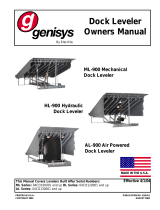
FROM CUSTOMER MAIN POWER & SAFETY
PROTECTION DEVICE.
110-120v. 1PH. 60HZ./208-240v. 1PH. 50HZ.
USE 20.0A/10.0A DUAL ELEMENT TIME DELAY FUSE
(1L1)
(N)
(1L1)
(N)
DUMMY
L1
SEE NOTE 2
FUSED DISCONNECT
(BY OTHERS)
N
G
1FU1 1L1
N
SEE NOTE 7
LD2
LD1
LD9
LD8
LD7
LD10
K3
K2
K1
J3
J5
J7
J2
J11
M2
RSOL1
RSOL2
RSOL3
M1
+12VDC
POWER CIRCUIT BOARD
SEE DETAIL - "A"
10FU1
MOTOR
12FU1
SOLENOID
11FU1
PWR SUPPLY
J2
12V
(12V)
(12V)
(12V)
(12V)
(12V)
X1/L1
X2/N
M1
M2
MCOM
SCOM
12VDC
12VDC
12VDC
12VDC
12VDC
12VDC
RSOL1
RSOL2
RSOL3
J7-3
J7-2
J7-1
J2-6
J2-5
J2-4
J2-3
J2-2
J2-1
J3-2
J3-1
J5-4
J5-3
J5-2
J5-1
G
120VAC, 0.3 AMPS
(BK) (WH)
POSN CYL "EXTEND" (SOLENOID 1)
RESTRAINT EXTEND
SOLENOID
(RSOL1/J73)
(SCOM/J51)
(SCOM/J151)
G
M
(M1/J54)
(MCOM/J52)
THERMAL SWITCH
(IN MOTOR)
SEE NOTE 2
G
120VAC, 0.3 AMPS
(BK) (WH)
POSN CYL "FLOAT" (SOLENOID 2)
(RSOL2/J72)
(SCOM/J151)
RESTRAINT FLOAT
SOLENOID
115V, 1PH, 50/60HZ
14.0/12.4 FLA, 1.0 HP;
(OVLD SET AT 12.4 AMPS)
132 J 4
M1 MCOM
123 J 4
M1 MCOM
RESTRAINT MOTOR
230V, 1PH, 50/60HZ
7.0/6.2 FLA, 1.0 HP;
(OVLD SET AT 6.2 AMPS)
ELECTRICAL SCHEMATIC - Standalone Power Unit
FIGURE 11A - STAND ALONE ELECTRICAL SCHEMATIC - PAGE 1 OF 3
/