Page is loading ...

ALIGNMENT OF THE INNER AND OUTER
AIR NOZZLES ON A HAUCK PROPORTIONING
OIL BURNER
Whenever a Hauck Proportioning Oil Burner is reassembled after either cleaning the burner or
replacing parts, the clearance between the Inner and Outer Air Nozzles should be checked. If
the clearance is not within the limits listed on Table1, the following instructions describe the
correct procedure to be used for setting this clearance:
1. Remove backplate assembly from burner body by removing bolts
which hold it to the body
2. Loosen the two Allen setscrews on each side of the operating lever collar
which holds it to the slotted sleeve.
3. Holding the operating lever in low position turn the inner nozzle so that it moves
away from the backplate as far as it will go. Then tighten lightly the one Allen set-
screw in lever which will be located toward the high side of the burner.
4. Move operating lever to high position. Replace the assembly in the burner and
tighten bolts which hold it to the body evenly and securely.
5. Hold three clearance wires (or narrow strip stock) of the proper thickness equally
spaced between the inner nozzle and outer nozzle and pull the operating lever to low
position all the way. The inner nozzle will then be spaced the proper distance from the
outer nozzle and the lever will slip on the operating sleeve to the low position.
6. Without moving lever, tighten securely the Allen setscrew in operating lever collar on
the high side. Move the lever to the high position and tighten securely the second Allen
setscrew in the collar lever at the low side.
INSTRUCTIONS
These instructions are intended to serve as guidelines covering the installation, operation, and maintenance of Hauck equipment. While
every attempt has been made to ensure completeness, unforeseen or unspecified applications, details, and variations may preclude
covering every possible contingency. WARNING: TO PREVENT THE POSSIBILITY OF SERIOUS BODILY INJURY, DO NOT USE OR
OPERATE ANY EQUIPMENT OR COMPONENT WITH ANY PARTS REMOVED OR ANY PARTS NOT APPROVED BY THE
MANUFACTURER. Should further information be required or desired or should particular problems arise which are not covered
sufficiently for the purchaser's purpose, contact Hauck Mfg. Co.
HAUCK MANUFACTURING CO., P.O. Box 90 Lebanon, PA 17042-0090 717-272-3051
Fax: 717-273-9882 780P-9.2
8/03 www.hauckburner.com

Page 2
780P-9.2
BURNER CLEARANCE
779 .007" - .010"
780 .010" - .012"
781 .010" - .012"
782 .010" - .015"
783 .010" - .015"
784 .050" - .062"
785 .050" - .062"
786 .050" - .062"
Table 1.
Figure 1. Drawing of the air nozzle control lever
showing the set screw locations.
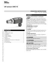
Figure 2. Schematic representation depicting
the inner and outer nozzles.
1/2