Page is loading ...

©2018 Warn Industries, Inc. WARN® and the WARN logo are trademarks of Warn Industries Inc. 1 102494A0
JEEP JK WRANGLER
FRONT CRAWLER BUMPER
Part Number: 102145, 102146, 102510, 102520
GENERAL SAFETY PRECAUTIONS
WARNING
IMPACT AND MOVING PARTS ENTANGLEMENT HAZARD
Failure to observe these instructions could lead to severe injury or death
• Always take time to fully read the Instructions and/or Operations Guide, and/or Basic Guide to Winching Techniques, in order to understand your winch and its operations.
• Always use extreme caution when drilling on any vehicle. Make sure that all fuel lines, brake lines, electrical wires, and other objects are not punctured or damaged when/if drilling on the
vehicle. Thoroughly inspect the area to be drilled (on both sides of material) prior to drilling, and relocate any objects that may be damaged. Failure to inspect the area to be drilled may result in
vehicle damage, electrical shock, re or personal injury.
• Always wear safety glasses when installing this kit. A drilling operation will cause ying metal chips. Flying chips can cause eye injury.
• Always use extreme caution when cutting and trimming during tting.
• Always remove jewelry and wear eye protection.
• Never lean over battery while making connections.
• Never route electrical cables:
o Across any sharp edges.
o Through or near moving parts.
o Near parts that become hot.
• Always insulate and protect all exposed wiring and electrical terminals.
• Always install terminal boots as directed in installation instructions.
• Always use appropriate and adequate care in lifting components into place.
• Always ensure components will remain secure during installation and operation.
• Always tighten all nuts and bolts securely, per the installation instructions.
• Always perform regular inspections and maintenance on the plow mechanism, fasteners, cable and related hardware.
• Always replace all worn or damaged parts before operating.
• Never operate this WARN product with damaged or missing parts.
Read installation and operating instructions thoroughly.
Your safety, and the safety of others, is very important. To help you make informed decisions about safety, we have
provided installation and operating instructions and other information on labels and in this guide. This information
alerts you to potential hazards that could hurt you or others. It is not possible to warn you about all potential hazards
associated with this product, you must use your own good judgment.
CARELESS INSTALLATION AND OPERATION CAN RESULT IN SERIOUS INJURY OR EQUIPMENT DAMAGE. READ AND
UNDERSTAND ALL SAFETY PRECAUTIONS AND OPERATING INSTRUCTIONS BEFORE INSTALLING AND OPERATING
THIS PRODUCT.
This guide identies potential hazards and has important safety messages that help you and others avoid personal injury
or death. WARNING and CAUTION are signal words that identify the level of hazard. These signal words mean:
WARNING signals a hazard that could cause serious injury or death, if you do not follow recommendations. CAUTION
signals a hazard that may cause minor to moderate injury, if you do not follow recommendations.
This guide uses NOTICE to call attention to important mechanical information, and Note: to emphasize general information
worthy of special attention.
BEFORE YOU BEGIN
THIS IS A 2-SIDED INSTRUCTION.
This side is for the the Jeep JK Wrangler.
Be sure to choose your precise application before you begin.

©2018 Warn Industries, Inc. WARN® and the WARN logo are trademarks of Warn Industries Inc. 2 102494A0
CAUTION
MOVING PARTS ENTANGLEMENT HAZARD
Failure to observe these instructions could lead to minor or moderate injury
• Always take time to fully read and understand the installation and Operations Guide included with this product.
• Never operate this product if you are under 16 years of age.
• Never operate this product when under the inuence of drugs, alcohol or medications.
Read installation and operating instructions thoroughly.
TABLE OF CONTENTS
Torque Specications ......................................................................page 2
Tools Required ................................................................................... page 3
Parts List...............................................................................................page 3
Installation ......................................................................................page 4-8
Maintenance/Care ............................................................................page 8
TORQUE SPECIFICATIONS
Please use the recommended torque specications when
assembling this product unless otherwise specied in the
instructions.
FASTENER SIZE FASTENER TORQUE FASTENER SIZE FASTENER TORQUE
lb-ft (N.m) lb-ft (N.m)
1/4" 8 (11) M4 (2) 3
5/16" 17 (23) M5 (4.5) 6
3/8" 30 (40) M6 (7.5) 10
7/16” 48 (66) M8 (18) 25
1/2" 74 (100) M10 (37) 50
9/16” 106 (144)
5/8" 148 (200)
3/4” 269 (364)
NOTICE
EQUIPMENT DAMAGE
• Never tow vehicle by attaching a tow bar to the eyelets on the bumper.
• Never attach tow bars directly to the bumper. Damage to bumper may occur. WARN bumpers are not designed to be used for at towing. Consult with the manufacturer of your tow bar system for the proper vehicle tow
bar brackets..
Read installation and operating instructions thoroughly.
NOTES
• The Warn Crawler Bumper will accept a large range of mid frame winches with up to 12,000 lb. capacities. The Bumper has been
designed to accommodate the standard 4-1/2 x 10” feet down mounting pattern as well as the 4-1/2 x 6” short drum pattern. The
Warn PowerPlant, 8274 and 9.5 CTI are NOT compatible with this bumper.
• Full width Crawler Bumpers are compatible with factory fog lamps using provided brackets. Stubby Crawler Bumpers do not reuse
factory fog lamps. Both Crawler Bumpers provide mounting locations for aftermarket lights on the top of the bumper.
• Both Crawler Bumper styles are not compatible with the factory skid plate and will not be reinstalled after installation of the
Crawler Bumper.
NOTICE
This product may interfere with driver assist systems such as adaptive cruise control and parking as-
sist systems that have sensors or cameras installed in the bumpers or front grill area. If your vehicle is
equipped with any of these systems or features, consult your vehicle owner’s manual before installing this
product. These systems may need to be disabled as a result of installing this product.

©2018 Warn Industries, Inc. WARN® and the WARN logo are trademarks of Warn Industries Inc. 3 102494A0
PARTS LIST
TOOLS REQUIRED
ID PN Description Qty.
A1 Varies Rock Crawler Bumper 1
A2 87398 Winch Mount Plate 1
A3 102148 RH Foglight Bracket 1
A4 102147 LH Foglight Bracket 1
A7 102521 LH Anti-Nod 1
A8 102522 RH Anti-Nod 1
A9 102727 Vacuum pump bracket 1
ID PN Description Qty.
B1 102491 Carriage Bolt - 1/2" - 13 x 1.25 8
B2 101259 Pushnut Bolt Retainer - 1/2" 8
B3 9213 Washer - 1/2" Plain Narrow 8
B4 29060 Locking Hex Nut - 1/2" - 13 8
B5 100772 Locking Plastic Plug - 3/8" 4
B6 83125 Flange Hex Nut - M6 x 1.0 4
B7 87166 Flange Nut Elastic Insert - M10 x 1.5 12
B8 93078 Flange Head Bolt - M10 x 1.5 x 25 8
B9 64108 Flange Head Capscrew - M6 x 1.0 x 25 6
B10 6819 Hex Head Capscrew - 5/8" - 11 x 1 1/2" 2
B11 82930 Washer- M6 plain at 4
B12 87167 Nut Elastic M6 2
B13 9471 Washer - 5/8" Plain Wide 2
B14 88041 Nut Plate Weldment - 5/8" - 11 2
B17 82351 Socket Head Capscrew - M4 x 0.7 x 16 4
B18 93675 Locking Hex Nut - M4 x 0.7 Nylon Insert 4
- Ratchet, extensions, universal - Metal cutting saw
- Sockets: Standard and Metric
- End Wrenches: Standard and Metric
- Open End Wrenches

©2018 Warn Industries, Inc. WARN® and the WARN logo are trademarks of Warn Industries Inc. 4 102494A0
INSTALLATION INSTRUCTIONS
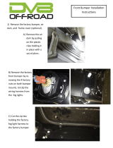
1. Remove factory bumper.
2. If reusing fog lights, be sure to remove from stock bumper.
3. Use a small at head screwdriver to pry wire harness clips
upward.
4. Disconnect fog light harness Christmas tree clips from the
factory bumper.
NOTE: You will need to secure wiring up in new bumper with
zip ties.
5. Install the eight 1/2” carriage bolts (B1) into the bumper
mounting slot (four each side).
IMPORTANT: Be sure that bolts are completely seated
in bumper (with square edges lined up with slot) before
securing push nut.
Aline
edges
Figure 1
Figure 2
Figure 3
Figure 4

©2018 Warn Industries, Inc. WARN® and the WARN logo are trademarks of Warn Industries Inc. 5 102494A0
Figure 6
Figure 5
6. Using a socket, secure bolt to bumper with push nut (B2).
TIP: Use an end of a tool to hold the back side of each bolt in
place while you secure push nut.
NOTE: The head of bolt will be in the inside of bumper hull
and the push nut will be on the outside.
7. Attach fog light to brackets (A3 and A4). NOTE: The fog
light may need to be trimmed to match the supplied fog
light bracket.
a. For LED fog lights: Secure light with two M6 ange head
bolts (B9) and M6 locking ange nuts (B6).
b. For HALOGEN fog lights: Secure with two M4
screws (B15) and M4 locking nut (B16).
NOTE: Halogen Fog light housing may need to be
trimmed to install further forward into bumper light
shroud.
NOTE: Your bracket may look dierent than image shows.
8. Attach fog light assemblies to bumper with two M10 ange
bolts (B8) and nuts (B7 ).
NOTE: Bracket mounting location may dier depending on
type of light.
Figure 7
INSTALLATION INSTRUCTIONS

©2018 Warn Industries, Inc. WARN® and the WARN logo are trademarks of Warn Industries Inc. 6 102494A0
NOTE: The next few steps are for the removal of the vacuum
pump. If your vehicle is not equipped with a vacuum pump,
move to step 14.
9. Remove the vacuum pump from factory bracket. Do not
remove any connections. Place pump up and out of the way
for now. Retain hardware for later reinstall.
WARNING
Always use extreme caution when cutting and trimming.
10. Use a saw to trim the right pump bracket arm. Be careful not
to damage any lines or wires.
11. Touch up raw edge with paint to prevent rust.
12. Carefully disconnect the hoses and electrical connection. Be
careful not to strain or kink the lines, wires or ttings.
13. Use a grinder or le to enlarge the slot in the factory pump
bracket to match the frame hole behind it, about 5/8”
diameter. Touch up raw edge with paint to prevent rust.
ANTI-NOD INSTALLATION
14. To install the anti-nod bracket, rst insert the nut plate (A6)
into the frame (driver’s side).
Figure 8
Figure 9
Figure 11
Trim
Enlarge slot
A6
INSTALLATION INSTRUCTIONS
Figure 10

©2018 Warn Industries, Inc. WARN® and the WARN logo are trademarks of Warn Industries Inc. 7 102494A0
15. Loosely secure top portion of anti-nod bracket between
bumper and frame using bolts (B8).
16. Line anti-nod bracket (A7) holes up with nut plate.
17. Insert bolt (B10) and washer (B13) through bracket, frame
and nut plate and tighten.
18. Tighten top bolts.
19. Repeat steps 15-17 for passenger side bracket (A8).
NOTE: You will not have a nut plate for passenger side
installation.
BUMPER INSTALLATION
20. With assistance, lift bumper in place (threading bolts
through frame mounting brackets).
21. Secure bumper to factory frame horns, using eight washers
(B3) and lock nuts (B4) (four each side).
NOTE: The next few steps are for the installation of the vacuum
pump. If your vehicle is not equipped with a vacuum pump,
move to step 25.
22. If your vehicle is equipped with a vacuum pump, install
the vacuum pump bracket (A9) (just behind the anti-nod
bracket) through bumper with bolt (B9), two washers (B11)
and nut (B12). Refer to exploded view on page 3.
23. Secure pump to bracket with one screw (B9), two washers
(B11) and nut (B12).
24. Secure pump to factory arm with factory hardware.
Figure 12
Figure 8
B8
A7
B10 & B13
A9
Factory
Hardware
B9, B11
and B12
Anti-Nod
Hardware
CAUTION
• Always use assistance when moving or lifting heavy parts.
INSTALLATION INSTRUCTIONS
Figure 13
Figure 14

©2018 Warn Industries, Inc. WARN® and the WARN logo are trademarks of Warn Industries Inc. 8 102494A0
25. Install fairlead to winch mounting bracket (A2).
26. Place winch mounting bracket on top of bumper (aligning
mounting holes). NOTE: We recommend getting assistance
to hold mounting bracket/fairlead in place to avoid tipping
hazard.
27. Install winch and wire to mounting bracket and bumper per
your winch installation instructions.
28. Tighten ALL hardware to specications on page 2.
29. Your installation is now complete.
Figure 15
Figure 16
MAINTENANCE / CARE
1. Inspect all parts on the winch, winch mount, and related hardware prior to each use. Replace all hardware that appears rusted or
deformed.
2. Inspect all nuts and bolts on the winch, winch mount and related hardware prior to each use. Tighten all nuts that appear to be
loose. Stripped, fractured, or bent bolts or nuts need to be replaced.
3. Check all cables prior to use. Replace cables that look worn or frayed.
4. Check all moving or rotating parts. Remove debris that may inhibit the part from moving freely.
/