Page is loading ...

125975-2
2/02
Obtaining Other Language Versions: To obtain information in another language about
the use of this product, please contact your local Crown Distributor. If you need assis-
tance locating your local distributor, please contact Crown at 574-294-8000.
This manual does not include all of the details of design, production, or variations of
the equipment. Nor does it cover every possible situation which may arise during in-
stallation, operation or maintenance.
The information provided in this manual was deemed accurate as of the publication
date. However, updates to this information may have occurred. To obtain the latest
version of this manual, please visit the Crown website at www.crownaudio.com.
Trademark Notice:
PIP and PIP2
are trademarks and
Crown, Macro-Tech
,
Com-Tech
,
IOC
and
P.I.P.
are registered trademarks of Crown International. Other trademarks are
the property of their respective owners.
©2002 by Crown Audio, Inc. P.O. Box 1000, Elkhart, Indiana 46515-1000 U.S.A.
Telephone: 574-294-8000
P.I.P.-XOV
Programmable Input Processor
REFERENCE
MANUAL

P.I.P.-XOV
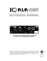
1 Welcome
Thank you for purchasing the
Crown
P.I.P.
®
-XOV
accessory.
PIP
TM
modules are designed to
quickly install in the rear panel
of many Crown amplifiers. PIP
stands for “Programmable Input
Processor.” Their versatile fea-
tures expand the capabilities of
your amplifier and enable you to
customize it for your particular
needs.
The P.I.P. -XOV is a versatile and
economical mono crossover filter
that plugs into Crown amplifiers
with PIP compatibility. It provides
high-pass and low-pass filters
with 18 dB/octave (3rd order)
slopes for bi-amp and tri-amp
systems.
Five two-position sliding switches
make it easy for the user to se-
lect one of twenty-four modes of
operation.
Plug-in resistor and capacitors
make it easy to change the cross-
over frequencies.
Features
❏ 18 dB/octave high-pass and
low-pass filters.
❏ User-selectable Butterworth,
Bessel, or Chebyshev response.
❏ Fully protected from output
shorts.
❏ Unity gain.
❏ Very economical.
❏ Twenty-four modes of operation.
❏ Both 3-pin XLR connectors and
1
/
4
-inch phone jacks are provided
for input and output connection.
Fig. 1.1 P.I.P.-XOV
Page 3

Page 4
P.I.P.-XOV
Fig. 2.1 Front & Bottom Views
A
B
S1 S2 S3 S4
S5
BACC B A
D E

Page 5
P.I.P.-XOV
D. Mode Switches
Five slide switches (S1–S5) are
used to configure the P.I.P.-XOV
in any of its 24 different modes
of operation. Each switch has
two positions: A (up) and B
(down). See the table in Figure
3.1 for a description of each
mode and their respective
switch settings.
E. User-Replaceable
Components
Six resistors (R1–R6) and six ca-
pacitors (C1–C6) can be easily
unplugged and replaced with
components of different values
to change both the crossover
frequency and the response
curve (Bessel, Butterworth, or
Chebyshev).
2 Facilities
A. Thumb Screws
Use these two thumb screws to fas-
ten the PIP to the amplifier. An E-ring
prevents them from falling out.
B. Balanced Phone Jacks
A balanced 1/4-inch phone jack is
provided at both the input and out-
put of the P.I.P.-XOV. Each phone
jack is parallel to its XLR connec-
tor counterpart.
C. XLR Connectors
A balanced 3-pin XLR connector is
provided at both the input and out-
put. A female connector is used for
the input and a male connector is
used for the output. These connec-
tors are wired with pin 2 high and
are parallel to their phone jack
counterparts.

P.I.P.-XOV
3 Installation
Mode of Operation
Use switches S1 through S5 to con-
figure the P.I.P.-XOV in the desired
operating mode. The following five
modes are just a sample of the
twenty-four different modes which
are available:
• Mode 3: High-pass to Ch. 1, low-
pass to Ch. 2, unprocessed sig-
nal to the output connectors for
daisy-chaining.
• Mode 5: Low-pass to Ch. 1, high-
pass to Ch. 2, unprocessed sig-
nal to the output connectors for
daisy-chaining.
• Mode 16: Band-pass to Ch. 1 for
mono operation, with unproc-
essed signal to the output con-
nectors for daisy-chaining.
• Mode 20: High-pass to Ch. 1 for
mono operation, with low-pass
signal routed to the output con-
nectors.
• Mode 22: Low-pass to Ch. 1 for
mono operation, with high-pass
signal routed to the output con-
nectors.
Figure 3.1 shows the switch settings
and explanation of each mode. The
MODE
SWITCH SETTINGS FUNCTION
S1 S2 S3 S4 S5 CH. 1 CH. 2
OUTPUT
CONNECTOR
1
2
3
4
5
6
7
8
9
10
11
12
13
14
15
16
17
18
19
20
21
22
23
24
A
A
A
A
A
A
A
A
A
A
A
A
A
A
B
B
B
B
B
B
B
B
B
B
A
A
A
A
A
A
A
B
B
B
B
B
B
B
A
A
A
B
B
B
B
B
B
B
A
A
A
B
B
B
B
A
A
A
B
B
B
B
X
X
X
A
A
A
B
B
B
B
A
B
B
A
A
B
B
A
B
B
A
A
B
B
A
B
B
A
B
B
A
A
B
B
X
A
B
A
B
A
B
X
A
B
A
B
A
B
X
A
B
X
A
B
A
B
A
B
LP
BP
HP
LP
LP
BP
HP
LP
BP
HP
LP
LP
BP
HP
LP
BP
HP
LP
BP
HP
LP
LP
BP
HP
LP
LP
LP
BP
HP
BP
HP
LP
LP
LP
BP
HP
BP
HP
MONO
MONO
MONO
MONO
MONO
MONO
MONO
MONO
MONO
MONO
FLAT
FLAT
FLAT
FLAT
FLAT
FLAT
FLAT
FLAT
FLAT
FLAT
LP
LP
LP
BP
HP
BP
HP
X = A or B
LP = Low-pass
HP = High-pass
BP = Band-pass
Fig. 3.1 Twenty-Four Operating Modes
Page 6

Page 7
P.I.P.-XOV
output connector is provided as a
convenient means for “daisy chain-
ing” the signal from amplifier to am-
plifier. However, please note that
modes 8–14 do
not provide any out-
put signal to the output connector.
Also note that modes 15–24 are to
be used
only with the amplifier con-
figured in one of its two mono
modes (BRIDGE-MONO or PAR-
ALLEL-MONO). When the P.I.P.-
XOV is placed in one of these
modes, no signal will be fed to the
input of Channel 2.
Diagrams illustrating the connec-
tion of each mode are included in
Appendix A to assist your selection.
Crossover Selection
The P.I.P.-XOV is factory-set for
a crossover frequency of 800 Hz
with a Butterworth response. In-
cluded with the PIP are additional
resistors to change the crossover
frequency to 100 or 500 Hz, and
capacitors to change it to 1, 5 or
8 kHz.
Changing the filter type or its
crossover frequency is simply a
matter of plugging in resistors
and capacitors of the desired val-
ues. Six resistors and six capaci-
tors are socketed for this purpose
(Figure 2.1).
Three filter types are available:
Bessel, Butterworth, and
Chebyshev. Each differs in its
ability to provide ideal frequency
response, a constant signal de-
lay, and large stopband attenua-
tion. A brief description of each
type follows:
B e s s e l
A Bessel filter provides minimum
phase distortion throughout its
passband (i.e. the most constant
signal delay), which is desirable
for pulse-type waveforms, but has
the poorest stopband attenuation
of the three filter types.
B u t t e r w o r t h
A Butterworth filter provides the
flattest response in the passband
with a moderate amount of
stopband attenuation. This filter is
most commonly used in crossover
applications.
C h e b y s h e v
A Chebyshev filter has more at-
tenuation in the stopband at the ex-
pense of ripple in the passband.
For example, a 0.5 dB Chebyshev
filter has attenuation varying from
0 dB to 0.5 dB in the passband,
but has attenuation in the stopband
greater than that of the other two
filter types.

Page 8
P.I.P.-XOV
The formulas shown below calcu-
late the correct component values
for the low-pass and high-pass fil-
ters. The value of constants K1, K2
and K3 determine the filter type.
Notice that the value of resistors
R1, R2 and R3 will always be equal.
The same is true of capacitors C4,
C5 and C6. Resistors R1–R5
should always be greater than 2 K
ohms and less than 330 K ohms.
Resistor R6 should always be less
than 1 M ohm. The value of ca-
pacitors C4, C5 and C6 can be
any arbitrary value so long as it
allows R1–R6 to meet the above
criteria.
All resistors should have a 1% tol-
erance and should be rated for
0.25 watt. All capacitors should
have a 10% tolerance and be of
the film type.
Fig. 3.2 Resistor / Capacitor Selection Values
Where:
π = 3.14159
F
L
= Low-pass crossover frequency (Hz)
F
H
= High-pass crossover frequency (Hz)
R = R1 = R2 = R3 (ohms)
C = C4 = C5 = C6 (farads)
Note: R1–R5 must all be > 2 K ohms and < 330 K ohms
and R6 must be < 1 M ohm. All resistors are 0.25 watt, 1%
and all capacitors are 10% film.
Filter Type K1 K2 K3
Bessel 0.988 1.423 0.2538
Butterworth 1.392 3.546 0.2024
0.1 dB Chebyshev 1.825 6.653 0.1345
0.25 dB Chebyshev 2.018 8.551 0.1109
0.5 dB Chebyshev 2.250 11.23 0.0895
1 dB Chebyshev 2.567 16.18 0.06428
2 dB Chebyshev 3.113 27.82 0.03113
3 dB Chebyshev 3.629 43.42 0.02533
K1
2 F R
π
L
C1 =
K2
2 F R
π
L
C2 =
K3
2 F R
π
L
C3 =
LOW-PASS
FILTER
1/K1
2 F C
π
H
R4 =
1/K2
2 F C
π
H
R5 =
1/K3
2 F C
π
H
R6 =
HIGH-PASS
FILTER

Page 9
P.I.P.-XOV
Fig. 3.3 Butterworth Filters
E x a m p l e
Suppose that you need a 0.25
Chebyshev high-pass filter with a
400 Hz cutoff. The preceding chart
shows the correct values for K1–K3:
K1=2.018, K2=8.551, and K3=
0.1109. Next choose an arbitrary
value for C (C4, C5, C6) which yields
R4 and R5 values approximately
within the range of 2 K to 330 K ohms
and a value for R6 less than 1 M ohm.
For this example, let C=0.01 mF.
Then:R4 = (1 / 2.018) / (2 x 3.14159
x 400 x 0.01 x 10E–6) = 19,717 ohms.
R5 = (1 / 8.551) / (2 x 3.14159 x
400 x 0.01 x 10E–6) = 4,563 ohms.
R6 = (1 / 0.1109) / (2 x 3.14159 x
400 x 0.01 x 10E–6) = 358,800
ohms.
The 1% precision resistors with the
closest values are: R4=19.6 K
ohms, R5=4,640 ohms, and
R6=357 K ohms.
Figure 3.3 lists the resistor and ca-
pacitor values for a Butterworth fil-
ter using K1=1.392, K2=3.546, and
K3=0.2024:

Page 10
P.I.P.-XOV
A guide to reading resistor color
codes is included in Appendix B for
your convenience.
Installation Procedures
You may need a phillips screwdriver
to remove the existing PIP module
or panel from your amplifier.
CAUTION: Before connecting this
or any PIP to your amplifier, it is
important to turn its level controls
down, turn it off and remove the
AC power. Don’t touch the cir-
cuitry while the amp is plugged
in. Even though the amplifier is
off, there could still be enough
energy remaining to cause elec-
tric shock.
1. Turn down the level controls (full
counterclockwise), turn off the
amplifier and unplug it from the AC
power source.
2. Remove the existing PIP module or
panel (two screws). For
PIP2
TM
amplifiers, this may involve
disconnecting the PIP from a PIP2
input adapter (see Figures 3.5 and
3.6). If a PIP2 input adapter is
already present, do not remove the
ribbon cables from the adapter.
Otherwise you will have to
reconnect them in the next step.
3.
Standard PIP Amplifiers
: Align the
edges of the P.I.P.–XOV
in the PIP
card rails and firmly push the unit in
until it is seated against the
mounting bracket (see Figure 3.4).
PIP2 Amplifiers:
(Requires a PIP2
input adapter. Crown part number
Q43528-1.) Connect the PIP2 input
adapter to the two input cables of
the amplifier (see Figure 3.5).
Notice that the PIP2 input adapter
should be positioned with the PIP
edge connector on top and facing
away from the amplifier. The 20-pin
cable (A) is connected first then the
18-pin cable (B) is connected. Both
ribbon cables should extend below
the PIP2 input adapter.
Next, insert the edge connector of
the P.I.P.–XOV into the PIP2 input
adapter (see Figure 3.6) and insert
the assembly into the PIP
opening in
the back of the amplifier.
4. Secure the P.I.P.–XOV
with the two
screws and lock washers provided.
(The lock washers are important
because they bond the PIP to the
chassis ground of the amplifier.)
5. Connect input and output wiring.
6. Plug in the amplifier and turn it on.
Adjust its level controls to a desired
setting.
Do not tamper with the circuitry.Circuit
changes made by unauthorized per-
sonnel, or unauthorized circuit modifi-
cations are not allowed.
Remember: Remember:
Remember: Remember:
Remember: Crown is not liable for any
damage resulting from overdriving other
components in your sound system.

Page 11
P.I.P.-XOV
Fig.3.5 PIP2 Input
Adapter Connection
Fig. 3.6 Installation
into a PIP2 Amplifier
Fig. 3.4 Installation into a
Standard PIP Amplifier

Page 12
P.I.P.-XOV
Connectors
Input:
Balanced female 3-pin XLR
and balanced 1/4-inch phone jack.
Output:
Balanced male 3-pin XLR
and balanced 1/4-inch phone jack.
(The input signal can be switched
to the output connector for external
“daisy chaining.”)
Power Requirements:
When plugged
into a
Macro-Tech
®
or
Com-Tech
®
amplifier, the PIP receives +/– 24 V
power.
Dimensions:
6 3/8 x 1 7/8 x 3 7/8 in.
16.2 x 4.8 x 9.8 cm.
Weight:
8.5 ounces (241 grams).
Note:
All specifications referenced
to a 0.775 V input signal.
4 Specifications
Signal to Noise:
Better than –85
dB with 800 Hz low-pass or high-
pass (equivalent input noise, 20
Hz to 20 kHz).
Input Impedance:
Nominally 20 K
ohms balanced and 10 K ohms un-
balanced.
Output:
10 VRMS balanced maxi-
mum.
Nominal Gain:
1.
Frequency Response:
+/– 0.75 dB,
dropping to –3 dB at the selected
crossover frequency (Butterworth
response). See Figures 4.1 to 4.4.
Filters:
One low-pass and one high-
pass with user-selectable filter type.
Factory-set for 3-pole Butterworth at
18 dB/octave with 800 Hz crossover
frequency. Bessel or Chebyshev
filters are also available.

Page 13
P.I.P.-XOV
15 100 1 K 4 K
6 dB
Fig. 4.1 Low-Pass Frequency Response
800 Hz Crossover Frequency
Fig. 4.2 Low-Pass Phase Response
800 Hz Crossover Frequency
15 100 1 K 4 K
45°

Page 14
P.I.P.-XOV
100 1 K 10 K
6 dB
100 1 K 10 K
45°
Fig. 4.3 High-Pass Frequency Response
800 Hz Crossover Frequency
Fig. 4.4 High-Pass Phase Response
800 Hz Crossover Frequency

P.I.P.-XOV
Appendix A:
Operating Modes
OUTPUT INPUT
CH. 2
LOW-PASS
CH. 1
LOW-PASS
INPUT
SIGNAL
FLAT
OUTPUT
FOR DAISY
CHAINING
MODE 1
OUTPUT INPUT
CH. 2
LOW-PASS
CH. 1
BAND-PASS
INPUT
SIGNAL
FLAT
OUTPUT
FOR DAISY
CHAINING
MODE 2
OUTPUT INPUT
CH. 2
BAND-PASS
CH. 1
LOW-PASS
INPUT
SIGNAL
FLAT
OUTPUT
FOR DAISY
CHAINING
MODE 4
OUTPUT INPUT
CH. 2
LOW-PASS
CH. 1
HIGH-PASS
INPUT
SIGNAL
FLAT
OUTPUT
FOR DAISY
CHAINING
MODE 3
A-1

P.I.P.-XOV
OUTPUT INPUT
CH. 2
HIGH-PASS
CH. 1
LOW-PASS
INPUT
SIGNAL
FLAT
OUTPUT
FOR DAISY
CHAINING
MODE 5
OUTPUT INPUT
CH. 2
BAND-PASS
CH. 1
BAND-PASS
INPUT
SIGNAL
FLAT
OUTPUT
FOR DAISY
CHAINING
MODE 6
OUTPUT INPUT
CH. 2
LOW-PASS
CH. 1
LOW-PASS
INPUT
SIGNAL
NO
OUTPUT
MODE 8
OUTPUT INPUT
CH. 2
HIGH-PASS
CH. 1
HIGH-PASS
INPUT
SIGNAL
FLAT
OUTPUT
FOR DAISY
CHAINING
MODE 7
A-2

P.I.P.-XOV
OUTPUT INPUT
CH. 2
LOW-PASS
CH. 1
BAND-PASS
INPUT
SIGNAL
NO
OUTPUT
MODE 9
OUTPUT INPUT
CH. 2
LOW-PASS
CH. 1
HIGH-PASS
INPUT
SIGNAL
NO
OUTPUT
MODE 10
OUTPUT INPUT
CH. 2
HIGH-PASS
CH. 1
LOW-PASS
INPUT
SIGNAL
NO
OUTPUT
MODE 12
OUTPUT INPUT
CH. 2
BAND-PASS
CH. 1
LOW-PASS
INPUT
SIGNAL
NO
OUTPUT
MODE 11
A-3

P.I.P.-XOV
OUTPUT INPUT
CH. 2
BAND-PASS
CH. 1
BAND-PASS
INPUT
SIGNAL
NO
OUTPUT
MODE 13
OUTPUT INPUT
CH. 2
HIGH-PASS
CH. 1
HIGH-PASS
INPUT
SIGNAL
NO
OUTPUT
MODE 14
OUTPUT INPUT
INPUT
SIGNAL
FLAT
OUTPUT
FOR DAISY
CHAINING
MODE 16
OUTPUT INPUT
MONO (CH. 1)
LOW-PASS
INPUT
SIGNAL
FLAT
OUTPUT
FOR DAISY
CHAINING
MODE 15
CONFIGURE AMPLIFIER
IN EITHER BRIDGE-MONO
OR PARALLEL-MONO
MODE.
MONO (CH. 1)
BAND-PASS
CONFIGURE AMPLIFIER
IN EITHER BRIDGE-MONO
OR PARALLEL-MONO
MODE.
A-4

P.I.P.-XOV
OUTPUT INPUT
INPUT
SIGNAL
LOW-PASS
OUTPUT
FOR 2ND
AMPLIFIER
MODE 20
OUTPUT INPUT
MONO (CH. 1)
BAND-PASS
INPUT
SIGNAL
LOW-PASS
OUTPUT
FOR 2ND
AMPLIFIER
MODE 19
CONFIGURE AMPLIFIER
IN EITHER BRIDGE-MONO
OR PARALLEL-MONO
MODE.
MONO (CH. 1)
HIGH-PASS
CONFIGURE AMPLIFIER
IN EITHER BRIDGE-MONO
OR PARALLEL-MONO
MODE.
OUTPUT INPUT
INPUT
SIGNAL
LOW-PASS
OUTPUT
FOR 2ND
AMPLIFIER
MODE 18
OUTPUT INPUT
MONO (CH. 1)
HIGH-PASS
INPUT
SIGNAL
FLAT
OUTPUT
FOR DAISY
CHAINING
MODE 17
CONFIGURE AMPLIFIER
IN EITHER BRIDGE-MONO
OR PARALLEL-MONO
MODE.
MONO (CH. 1)
LOW-PASS
CONFIGURE AMPLIFIER
IN EITHER BRIDGE-MONO
OR PARALLEL-MONO
MODE.
A-5

P.I.P.-XOV
OUTPUT INPUT
INPUT
SIGNAL
HIGH-PASS
OUTPUT
FOR 2ND
AMPLIFIER
MODE 24
OUTPUT INPUT
MONO (CH. 1)
BAND-PASS
INPUT
SIGNAL
BAND-PASS
OUTPUT
FOR 2ND
AMPLIFIER
MODE 23
CONFIGURE AMPLIFIER
IN EITHER BRIDGE-MONO
OR PARALLEL-MONO
MODE.
MONO (CH. 1)
HIGH-PASS
CONFIGURE AMPLIFIER
IN EITHER BRIDGE-MONO
OR PARALLEL-MONO
MODE.
OUTPUT INPUT
INPUT
SIGNAL
HIGH-PASS
OUTPUT
FOR 2ND
AMPLIFIER
MODE 22
OUTPUT INPUT
MONO (CH. 1)
LOW-PASS
INPUT
SIGNAL
BAND-PASS
OUTPUT
FOR 2ND
AMPLIFIER
MODE 21
CONFIGURE AMPLIFIER
IN EITHER BRIDGE-MONO
OR PARALLEL-MONO
MODE.
MONO (CH. 1)
LOW-PASS
CONFIGURE AMPLIFIER
IN EITHER BRIDGE-MONO
OR PARALLEL-MONO
MODE.
A-6

P.I.P.-XOV
Appendix B:
Reading Component Values
Capacitors
Capacitors’ values are usually stamped on the capacitor. However, not all
capacitors are labeled the same way. For example, a 0.022 microfarad
(µF) capacitor may be marked as .022 K, 22n, .022 µF, or 223 K. The last
example could be read 22 x 10
3
picofarads (pF), where 1 pF=10
6
µF.
Resistors
Figure B.1 shows how to read the value of a resistor:
R E S I S T O R C O L O R C O D E
SIGNIFICANT FIGURES
(1st, 2nd, 3rd BANDS)
BLACK
BROWN
RED
ORANGE
YELLOW
GREEN
BLUE
VIOLET
GRAY
WHITE
O
1
2
3
4
5
6
7
8
9
BLACK
BROWN
RED
ORANGE
YELLOW
1
10
100
1,000
10,000
GREEN
BLUE
VIOLET
GRAY
WHITE
100,000
1,000,000
10,000,000
100,000,000
1,000,000,000
MULTIPLIER (4th BAND)
TOLERANCE (5th BAND)
SILVER
GOLD
RED
BROWN
10%
5%
2%
1%
1% tolerance resistors are recommended.
Resistors with 5% or 10% tolerance have two (instead of three) significant figures.
The third band is the multiplier and the fourth is the tolerance.
EXAMPLE:
WHITE
GREEN
ORANGE
BROWN
BROWN
953101%
x
ANSWER:
9530 OHMS (OR 9.53 K OHMS)
WITH 1% TOLERANCE
Fig. B.1 Reading Resistor Color Codes
B-1
/