Fujitsu ARYG24LMLA Installation guide
- Category
- Split-system air conditioners
- Type
- Installation guide

EnglishDeutschFrançaisEspañolItalianoEλληvIkάPortuguês
Русский
Turkiçe
INSTALLATION MANUAL
For authorized service personnel only.
INSTALLATIONSANLEITUNG
Nur für autorisiertes Personal.
MANUEL D'INSTALLATION
Pour le personnel agréé uniquement.
MANUAL DE INSTALACIÓN
Solo para personal autorizado.
MANUALE D'INSTALLAZIONE
Ad uso esclusivo del personale autorizzato.
ΕΓΧΕΙΡΙΔΙΟ ΕΓΚΑΤΑΣΤΑΣΗΣ
Για εξουσιοδοτημένο προσωπικό σέρβις.
MANUAL DE INSTALAÇÃO
Apenas para técnicos autorizados.
РУКОВОДСТВО ПО УСТАНОВКЕ
Для уполномоченного персонала.
KURULUM KILAVUZU
Yetkili servis personeli içindir.
PART NO. 9379127035-02
AIR CONDITIONER
9379127035-02_IM.indb 19379127035-02_IM.indb 1 23/01/2013 16:24:4023/01/2013 16:24:40

En-1
CAUTION
Read carefully all security information before use or install the air conditioner.
Do not attempt to install the air conditioner or a part of the air conditioner by yourself.
This unit must be installed by qualified personnel with a capacity certificate for handling
refrigerant fluids. Refer to regulation and laws in use on installation place.
Th
e installation must be carried out in compliance with regulations in force
in the place
of installation and the installation instructions of the manufacturer.
This unit is part of a set constituting an air conditioner. It must not be installed alone or
with non-authorized by the manufacturer.
Always use a separate power supply line protected by a circuit breaker operating on all
wires with a distance between contact of 3mm for this unit.
The unit must be correctly grounded and the supply line must be equipped with a
differential breaker in order to protect the persons.
The units are not explosion proof and therefore should not be installed in explosive
atmosphere.
Never touch electrical components immediately after the power supply has been turned
off. Electric shock may occur. After turning off the power, always wait 5 minutes before
touching electrical components.
This unit contains no user-serviceable parts. Always consult authorized service
personnel to repairs.
When moving, consult authorized service personnel for disconnection and installation of
the unit.
This appliance is not intended for use by persons (including children) with reduced
physical, sensory or mental capabilities, or lack of experience and knowledge, unless
they have been given supervision or instruction concerning use of the appliance by a
person responsible for their safety. Children should be supervised to ensure that they do
not play with the appliance.
2. ABOUT THE UNIT
2.1. Precautions for using the R410A refrigerant
WARNING
Do not introduce any substance other than the prescribed refrigerant into the
refrigeration cycle.
If air enters the refrigeration cycle, the pressure in the refrigeration cycle will become
abnormally high and cause the piping to rupture.
If there is a refrigerant leakage, make sure that it does not exceed the concentration
limit.
If a refrigerant leakage exceeds the concentration limit, it can lead to accidents such as
oxygen starvation.
Do not touch refrigerant that has leaked from the refrigerant pipe connections or other
area. Touching the refrigerant directly can cause frostbite.
If a refrigerant leakage occurs during operation, immediately vacate the premises and
thoroughly ventilate the area.
If the refrigerant comes in contact with a fl ame, it produces a toxic gas.
2.2. Special tool for R410A
WARNING
To install a unit that uses the R410A refrigerant, use dedicated tools and piping
materials that have been manufactured specifi cally for R410A use.
Because the pressure of the R410A refrigerant is approximately 1.6 times higher than
the R22, failure to use dedicated piping material or improper installation can cause
rupture or injury.
Furthermore, it can cause serious accidents such as water leakage, electric shock, or
fi re.
Tool name Contents of change
Gauge manifold
Pressure is huge and cannot be measured with a conventional
gauge. To prevent erroneous mixing of other refrigerants, the
diameter of each port has been changed.
It is recommended to use a gauge manifold with a high pressure
display range –0.1 to 5.3 MPa and a low pressure display range
–0.1 to 3.8 MPa.
Charging hose
To increase pressure resistance, the hose material and base
size were changed.
Vacuum pump
A conventional vacuum pump can be used by installing a
vacuum pump adapter.
Gas leakage
detector
Special gas leakage detector for HFC refrigerant R410A.
1. SAFETY PRECAUTIONS
• Be sure to read this Manual thoroughly before installation.
• The warnings and precautions indicated in this Manual contain important information
pertaining to your safety. Be sure to observe them.
• Hand this Manual, together with the Operating Manual to the customer.
Request the customer to keep them on hand for future use, such as for relocating or
repairing the unit.
WARNING
This mark indicates procedures which, if improperly performed,
might lead to the death or serious injury of the user.
CAUTION
This mark indicates procedures which, if improperly performed,
might possibly result in personal harm to the user, or damage to
property.
WARNING
Request your dealer or a professional installer to install the indoor unit in accordance
with this Installation Manual. An improperly installed unit can cause serious accidents
such as water leakage, electric shock, or fi re. If the indoor unit is installed in disregard
of the instructions in the Installation Manual, it will void the manufacturer’s warranty.
Do not turn ON the power until all work has been completed. Turning ON the power
before the work is completed can cause serious accidents such as electric shock or fi re
.
If refrigerant leaks while work is being carried out, ventilate the area. If the refrigerant
comes in contact with a fl ame, it produces a toxic gas.
Installation work must be performed in accordance with national wiring standards by
authorized personnel only.
Except for EMERGENCY, never turn off main as well as sub breaker of the indoor units
during operation. It will cause compressor failure as well as water leakage.
First, stop the indoor unit by operating the control unit, converter or external input
device and then cut the breaker.
Make sure to operate through the control unit, converter or external input device.
When the breaker is designed, locate it at a place where the users cannot start and
stop in the daily work.
Contents
1. SAFETY PRECAUTIONS ..........................................................................................1
2. ABOUT THE UNIT .....................................................................................................1
2.1. Precautions for using the R410A refrigerant .......................................................1
2.2. Special tool for R410A ........................................................................................1
2.3. Accessories ........................................................................................................2
2.4. Optional parts .....................................................................................................2
3. INSTALLATION WORK .............................................................................................2
3.1. Selecting an installation location ........................................................................2
3.2. Installation dimension .........................................................................................3
3.3. Installation the unit ..............................................................................................3
4.
PIPE INSTALLATION ................................................................................................4
4.1. Selecting the pipe material .................................................................................4
4.2. Pipe requirement ................................................................................................5
4.3. Flare connection (Pipe connection) ....................................................................5
4.4. Installing heat insulation .....................................................................................6
5. INSTALLING DRAIN HOSE .......................................................................................6
6. ELECTRICAL WIRING ..............................................................................................7
6.1. Wiring system diagram .......................................................................................7
6.2. Connection cable preparation .............................................................................8
6.3. Connection of wiring ...........................................................................................8
7. REMOTE CONTROLLER SETTING .........................................................................9
7.1. Installing the remote controller ...........................................................................9
7.2. Setting the DIP switches .....................................................................................9
8. FUNCTION SETTING..............................................................................................10
8.1. Turning on the power ........................................................................................10
8.2. Function setting ................................................................................................10
8.3. Static pressure characteristic ...........................................................................12
8.4. Special installation methods .............................................................................12
9. FRESH AIR INTAKE ................................................................................................13
10. TEST RUN ...............................................................................................................14
11. CHECK LIST ............................................................................................................14
12. OPTIONAL KIT INSTALLATION (OPTION) .............................................................14
13. CUSTOMER GUIDANCE ........................................................................................15
14. ERROR CODES ......................................................................................................15
INSTALLATION MANUAL
PART NO. 9379127035
INDOOR UNIT (Duct Type)
9379127035-02_IM.indb Sec1:19379127035-02_IM.indb Sec1:1 23/01/2013 16:25:4023/01/2013 16:25:40

En-2
2.3. Accessories
WARNING
For installation purposes, be sure to use the parts supplied by the manufacturer or
other prescribed parts.
The use of non-prescribed parts can cause serious accidents such as the unit to fall,
water leakage, electric shock, or fi re.
The following installation parts are furnished. Use them as required.
Keep the Installation Manual in a safe place and do not discard any other accessories
until the installation work has been completed.
Do not discard any accessories needed for installation until the installation work has
been completed.
Name and Shape Q’ty Description
Operating manual
1
Installation manual
1
(This book)
Hanger
4
For suspending the indoor unit
from ceiling
Drain hose insulation
1
Insulates the drain hose and
vinyl hose
Cable tie (large)
1
For fi xing the drain hose
Cable tie (small)
1
For remote controller and re-
mote controller cable binding
Cable tie
2
For electrical wiring
(22,24 model)
Wire clamper
1
For electrical wiring
(22,24 model)
Remote controller
1
For air conditioner operation
Remote controller cable
(*1)
1
For connecting the remote
controller
Screw (M4 × 16)
2
For installing the remote
controller
Coupler heat
insulation (large)
1
For indoor side pipe joint (gas)
Coupler heat
insulation (small)
1
For indoor side pipe joint
(liquid)
Special nut A
(large fl ange)
4
For suspending the indoor unit
from ceiling
Special nut B
(small fl ange)
4
For suspending the indoor unit
from ceiling
(*1) Not supplied for ART series
2.4. Optional parts
Parts name Model No. Application
Wired remote controller UTY-RNN*M For air conditioner operation
Wired remote controller UTY-RVN*M For air conditioner operation
Simple remote controller UTY-RSN*M For air conditioner operation
Remote sensor unit UTY-XSZX Room temperature sensor
External connect kit UTD-ECS5A For control input/output port
Square fl ange UTD-SF045T
Round fl ange UTD-RF204
Long-life fi lter UTD-LF25NA
Drain pump unit
UTZ-PX1NBA
3. INSTALLATION WORK
3.1. Selecting an installation location
Especially, the installation place is very important for the split type air conditioner be-
cause it is very diffi cult to move from place to place after the fi rst installation.
WARNING
Select installation locations that can properly support the weight of the indoor. Install
the units securely so that they do not topple or fall.
CAUTION
Do not install the unit in the following areas:
• Area with high salt content, such as at the seaside.
It will deteriorate metal parts, causing the parts to fail or the unit to leak water.
• Area fi lled with mineral oil or containing a large amount of splashed oil or steam,
such as a kitchen.
It will deteriorate plastic parts, causing the parts to fail or the unit to leak water.
• Area that generates substances that adversely affect the equipment, such as
sulfuric gas, chlorine gas, acid, or alkali.
It will cause the copper pipes and brazed joints to corrode, which can cause
refrigerant leakage.
• Area that can cause combustible gas to leak, contains suspended carbon fi bers or
fl ammable dust, or volatile infl ammables such as paint thinner or gasoline.
If gas leaks and settles around the unit, it can cause a fi re.
• Area where animals may urinate on the unit or ammonia may be generated.
Do not use the unit for special purposes, such as storing food, raising animals, growing
plants, or preserving precision devices or art objects.
It can degrade the quality of the preserved or stored objects.
Do not install where there is the danger of combustible gas leakage.
Do not install the unit near a source of heat, steam, or fl ammable gas.
Install the unit where drainage does not cause any trouble.
Install the indoor unit, outdoor unit, power supply cable, transmission cable, and remote
controller cable at least 1 m away from a television or radio receivers. The purpose of
this is to prevent TV reception interference or radio noise.
(Even if they are installed more than 1 m apart, you could still receive noise under
some signal conditions.)
Take precautions to prevent the unit from falling.
Decide the mounting position with the customer as follows:
(1) Install the indoor unit in a location having suffi cient strength to support the weight of
the indoor unit.
(2) The inlet and outlet ports should not be obstructed; the air should be able to blow all
over the room.
9379127035-02_IM.indb Sec1:29379127035-02_IM.indb Sec1:2 23/01/2013 16:25:4023/01/2013 16:25:40

En-3
(3) Leave the space required to service the air conditioner.
(4) Locate where the air can be distributed evenly throughout the room by the unit.
(5) Install the unit where connection to the outdoor unit is easy.
(6) Install the unit where the connection pipe can be easily installed.
(7) Install the unit where the drain pipe can be easily installed.
(8) Install the unit where noise and vibration is not amplifi ed.
(9) Take servicing, etc., into consideration and leave the spaces. Also install the unit
where the fi lter can be removed.
(10) Providing as much space as possible between the indoor unit and the ceiling will
make work much easier.
(11) If installing in a place where its humidity exceeds 80%, use heat insulation to prevent
condensation.
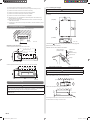
3.2. Installation dimension
Provide the space around the unit as shown in the following fi gure.
Floor
Unit : mm
2500 or more
(When no
ceiling)
300
or more
150
or more
Maintenance hole dimensions:
It shall be possible to install and remove the control box.
Maintenance hole
Control box
Unit : mm
It shall be possible to install and remove the control box, fan units and fi lter.
Maintenance hole
Intake panel
Control box
Unit : mm
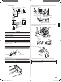
3.3. Installation the unit
WARNING
Install the air conditioner in a location which can withstand a load do at least 5 times the
weight of the main unit and which will not amplify sound or vibration. If the installation
location is not strong enough, the indoor unit may fall and cause injuries.
If the job is done with the panel frame only, there is a risk that the unit will come loose.
Please take care.
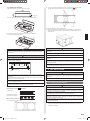
3.3.1. Installing the hangers
WARNING
When fastening the hangers, make the bolt positions uniform.
Hanging bolt installation diagram.
(Example)
(Top side)
(Left side)
Unit : mm
The distance of is adjustable according to the place of the hanging bolts.
(MAX : 550 mm, MIN : 410 mm)
Slide the unit in the arrow direction and fasten it.
Hanging bolt M10
(Obtained locally)
Special nut A
Washer
(Obtained locally)
Special nut B
Hanger
Bolt Strength [N·m (kgf·cm)] 9.81 to 14.71 (100 to 150)
CAUTION
Fasten the unit securely with special nuts A and B.
3.3.2. Leveling
Base vertical direction leveling on the unit (right and left).
(Left side)
Lever meter
AIR
AIR
Base horizontal direction leveling on top of the unit.
Drain hose
0-5 mm
Give a slight tilt to the side to which the drain hose is connected.
The tilt should be in the range of 0 mm to 5 mm.
9379127035-02_IM.indb Sec1:39379127035-02_IM.indb Sec1:3 23/01/2013 16:25:4123/01/2013 16:25:41

En-4
3.3.3. Intake duct connection
Follow the procedure in the following fi gure to the ducts.
Unit : mm
The air inlet duct can be changed by replacing the intake grille and fl ange.
For the bottom air intake, follow the procedure of
1
→
2
for installation.
(The factory setting is back air intake.)
1
2
CAUTION
When air is taken in from the bottom side, the operating sound of the product will easily
enter the room. Install the product and intake grilles where the affect of the operating
sound is small.
CAUTION
If an intake duct is installed, take care not to damage the temperature sensor.
Be sure to install the air inlet grille and the air outlet grille for air circulation. The correct
temperature cannot be detected.
Unit
Air Outlet Grille
Air Inlet Grille
(Room)
When connecting the duct, perform duct-insulation that is appropriate for the installing
environment.
Inappropriate insulation work may cause condensation on the surface of the insulating
material, and may lead condensation drip.
Grills must be fi xed so that man cannot touch indoor unit fan, and cannot be removed
by only hand operation without tool.
Be sure to install the air fi lter in the air inlet. If the air fi lter is not installed, the heat
exchanger may be clogged and its performance may decrease.
3.3.4. Outlet duct connection
Duct installation pattern ( CUT PART)
Square duct(1)
(2) Round duct outlet ×4
(This is the factory setting.)
When using as a square duct
(1) Cut the slit seam
with a cutter.
Turn up the insulation around the points to be cut according to the outlet port shape (2)
working points so that the insulation does not stick out at the
part.
Cut Cut
Cut
Cut
Cut with nippers and remove the sheet metal.(3)
Since there is a slit in the insulation, use radio pliers, tweezers, etc. to stretch the (4)
screw hole part used when installing the round fl ange and square fl ange when con-
necting the duct.
CAUTION
Check that duct work does not exceed the range of external static pressure of
equipment.
Make sure to insulate ducts to avoid the dew condensation.
Make sure to insulate between ducts and walls if metal ducts are used.
Please explain handling and washing methods of locally purchased materials to the
customer.
To prevent people from touching the parts inside the unit, be sure to install grilles on
the inlet and outlet ports. The grilles must be designed in such a way that cannot be
removed without tools.
When connecting the duct to the outlet port of the indoor unit, be sure to insulate the
outlet port and the installation screws to prevent water from leaking around the port.
4.
PIPE INSTALLATION
CAUTION
Be careful that foreign matter (oil, water, etc.) does not enter the piping with refrigerant
R410A models. Also, when storing the piping, securely seal the openings by pinching,
taping, etc.
While brazing the pipes, be sure to purge with dry nitrogen gas.
4.1. Selecting the pipe material
CAUTION
Do not use existing pipes.
Use pipes that have clean external and internal sides without any contamination which
may cause trouble during use, such as sulfur, oxide, dust, cutting waste, oil, or water.
It is necessary to use seamless copper pipes.
Material : Phosphor deoxidized seamless copper pipes
It is desirable that the amount of residual oil is less than 40 mg/10 m.
Do not use copper pipes that have a collapsed, deformed, or discolored portion
(especially on the interior surface). Otherwise, the expansion valve or capillary tube
may become blocked with contaminants.
Improper pipe selection will degrade performance. As an air conditioner using R410A
incurs pressure higher than when using conventional refrigerant, it is necessary to
choose adequate materials.
•
Thicknesses of copper pipes used with R410A are as shown in the table.
•
Never use copper pipes thinner than those indicated in the table even if they are
available on the market.
9379127035-02_IM.indb Sec1:49379127035-02_IM.indb Sec1:4 23/01/2013 16:25:4123/01/2013 16:25:41

En-5
Width across
fl ats
Pipe outside
diameter [mm (in.)]
Width across flats
of Flare nut [mm]
6.35 (1/4) 17
9.52 (3/8) 22
12.70 (1/2) 26
15.88 (5/8) 29
19.05 (3/4) 36
4.3.2. Bending pipes
•
If pipes are shaped by hand, be careful not to collapse them.
•
Do not bend the pipes in an angle more than 90°.
•
When pipes are repeatedly bend or stretched, the material will harden, making it
diffi cult to bend or stretch them any more.
•
Do not bend or stretch the pipes more than 3 times.
CAUTION
To prevent breaking of the pipe, avoid sharp bends.
If the pipe is bent repeatedly at the same place, it will break.
4.3.3. Pipe connection
CAUTION
Be sure to install the pipe against the port on the indoor unit correctly. If the centering
is improper, the fl are nut cannot tighten smoothly. If the fl are nut is forced to turn, the
threads will be damaged.
Do not remove the flare nut from the indoor unit pipe until immediately before
connecting the connection pipe.
Do not use mineral oil on fl ared part. Prevent mineral oil from getting into the system
as this would reduce the lifetime of the units.
Be sure to connect the gas pipe after connecting the liquid pipe completely.
Detach the caps and plugs from the pipes.(1)
Center the pipe against the port on the indoor unit, and then turn the fl are nut by (2)
hand.
When the fl are nut is tightened properly by your hand, hold the body side coupling (3)
with a separate spanner, then tighten with a torque wrench. (See the table below for
the fl are nut tightening torques.)
CAUTION
Hold the torque wrench at its grip, keeping it at a right angle with the pipe, in order to
tighten the fl are nut correctly.
Tighten the flare nuts with a torque wrench using the specified tightening method.
Otherwise, the fl are nuts could break after a prolonged period, causing refrigerant to
leak and generate a hazardous gas if the refrigerant comes into contact with a fl ame.
Connect the piping so that the control box cover can easily be removed for servicing
when necessary.
In order to prevent water from leaking into the control box, make sure that the piping is
well insulated.
When the fl are nut is tightened properly by your hand, hold the body side coupling with
a separate spanner, then tighten with a torque wrench. (See the table below for the fl are
nut tightening torques.)
Tighten with 2 wrenches.
Holding wrench
Flare nut
Connection pipe
Torque wrench
Indoor unit pipe
(Body side)
Flare nut [mm (in.)] Tightening torque [N·m (kgf·cm)]
6.35 (1/4) dia. 16 to 18 (160 to 180)
9.52 (3/8) dia. 32 to 42 (320 to 420)
12.70 (1/2) dia. 49 to 61 (490 to 610)
15.88 (5/8) dia. 63 to 75 (630 to 750)
19.05 (3/4) dia. 90 to 110 (900 to 1,100)
Thicknesses of Annealed Copper Pipes (R410A)
Pipe outside diameter [mm (in.)] Thickness [mm]
6.35 (1/4) 0.80
9.52 (3/8) 0.80
12.70 (1/2) 0.80
15.88 (5/8) 1.00
19.05 (3/4) 1.20
4.2. Pipe requirement
CAUTION
Refer to the Installation Manual of the outdoor unit for description of the length of
connecting pipe or for difference of its elevation.
Install heat insulation around both the gas and liquid pipes. Failure to do so may cause
water leaks.
Use heat insulation with heat resistance above 120 °C. (Reverse cycle model only)
In addition, if the humidity level at the installation location of the refrigerant piping is
expected to exceed 70 %, install heat insulation around the refrigerant piping. If the
expected humidity level is 70-80 %, use heat insulation that is 15 mm or thicker and if
the expected humidity exceeds 80 %, use heat insulation that is 20 mm or thicker. If
heat insulation is used that is not as thick as specifi ed, condensation may form on the
surface of the insulation. In addition, use heat insulation with heat conductivity of 0.045
W/(m·K) or less (at 20 °C).
Use pipe with water-resistant heat insulation.
4.3. Flare connection (Pipe connection)
WARNING
Tighten the flare nuts with a torque wrench using the specified tightening method.
Otherwise, the fl are nuts could break after a prolonged period, causing refrigerant to
leak and generate a hazardous gas if the refrigerant comes into contact with a fl ame.
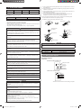
4.3.1. Flaring
Use special pipe cutter and fl are tool exclusive for R410A.
(1)
Cut the connection pipe to the necessary length with a pipe cutter.
(2)
Hold the pipe downward so that cuttings will not enter the pipe and remove any
burrs.
(3)
Insert the fl are nut (always use the fl are nut attached to the indoor and outdoor units
respectively) onto the pipe and perform the fl are processing with a fl are tool. Use
the special R410A fl are tool, or the conventional fl are tool. Leakage of refrigerant
may result if other fl are nuts are used.
(4)
Protect the pipes by pinching them or with tape to prevent dust, dirt, or water from
entering the pipes.
L
Die
Pipe
A
B
Check if [L] is fl ared uniformly
and is not cracked or scratched.
Pipe outside diameter
[mm (in.)]
Dimension A [mm]
Dimension B
-
0
0.4
[mm]
Flare tool for R410A,
clutch type
6.35 (1/4)
0 to 0.5
9.1
9.52 (3/8) 13.2
12.70 (1/2) 16.6
15.88 (5/8) 19.7
19.05 (3/4) 24.0
When using conventional fl are tools to fl are R410A pipes, the dimension A should be ap-
proximately 0.5 mm more than indicated in the table (for fl aring with R410A fl are tools)
to achieve the specifi ed fl aring. Use a thickness gauge to measure the dimension A.
9379127035-02_IM.indb Sec1:59379127035-02_IM.indb Sec1:5 23/01/2013 16:25:4123/01/2013 16:25:41

En-6
4.4. Installing heat insulation
CAUTION
After checking for gas leaks (refer to the Installation Manual of the outdoor unit),
perform this section.
Install heat insulation around both the large (gas) and small (liquid) pipes. Failure to do
so may cause water leaks.
After checking for gas leaks, insulate by wrapping insulation around the two parts (gas
and liquid) of the indoor unit coupling, using the Coupler Heat Insulation.
After installing the Coupler Heat Insulation, wrap both ends with vinyl tape so that there is
no gap.
Coupler heat insulation
No gap
Coupler heat
insulation
Body
Be sure to overlap the
insulation
CAUTION
Must fi t tightly against body without any gap.
5. INSTALLING DRAIN HOSE
Install the drain hose according to the measurements given in the following fi gure.
(Left side)
(Right side)
Liquid pipe
Drain pipe
38 mm (O.D.)
Gas pipe
Drain pipe
38 mm (O.D.)
The drain cap is attached
at the factory setting.
Unit : mm
CAUTION
Install the drain hose in accordance with the instructions in this Installation Manual and
keep the area warm enough to prevent condensation. Problems with the piping may
lead to water leaks.
NOTE:
Install the drain hose.
Install the drain hose with downward gradient (1/50 to 1/100) and so there are no rises or •
traps in the hose.
Use general hard polyvinyl chloride pipe (VP25) [outside diameter 38 mm] and connect it •
with adhesive (polyvinyl chloride) so that there is no leakage.
When the hose is long, install supporters.•
Do not perform air bleeding.•
Always heat insulate the indoor side of the drain hose.•
Outlet
air fl ow
Drain
hose
Trap
Arrange the drain hose lower
than this portion.
Rise
Air bleeding
Supporter
GOOD
PROHIBITED
PROHIBITED
PROHIBITED
1.5 to 2 m
When the unit is shipped from the factory, the drain port is on the left side (control box side).•
When using the drain port on the right side of the unit, reinstall the drain cap to the left •
side drain port.
Drain port Drain cap
Cable tie
CAUTION
Always check that the drain cap is installed to the unused drain port and is fastened
with the Cable tie.
If the drain cap is not installed, or is not suffi ciently fastened by the Cable tie, water
may drip during the cooling operation.
Cut the drain hose insulation at a position approximately 80 mm from the end with •
cutters, etc.
Stick the large drain hose insulation at the drain hose installation side.•
Stick the small drain hose insulation at the drain cap side.•
Drain hose
insulation
(large)
Drain hose
Drain hose insulation (small)
Drain hose
insulation
(small)
Drain hose
Drain hose
insulation
(large)
Drain cap
unit
unit
Unit
Unit
Unit : mm
Cut line
Cover the drain cap with the drain hose insulation.•
9379127035-02_IM.indb Sec1:69379127035-02_IM.indb Sec1:6 23/01/2013 16:25:4223/01/2013 16:25:42

En-7
6. ELECTRICAL WIRING
Cable Cable size (mm
2
) Type Remarks
Connection cable 1.5 (MIN.) Type 60245 IEC57 3Cable+Ground, 1φ230V
Max. Cable Length: Limit voltage drop to less than 2%. Increase cable gauge if voltage drop is
2% or more.
For simultaneous multi ( 22,24 model only )
Conductor size (mm
2
) Max length (m)
Bus wire 0.3 (MIN.) 500*
* This length shall be the total extended length in the system of the group.
(Total length of bus wire and remote controller cable.)
Install all electrical works in accordance to standard.•
Install the disconnect device with a contact gap of at least 3mm in all poles nearby the •
units. (Both indoor unit and outdoor unit)
Wiring size must comply with the applicable country or region's regulations.•
WARNING
Electrical work must be performed in accordance with this Manual by a person certifi ed
under the national or regional regulations. Be sure to use a dedicated circuit for the
unit.
An insuffi cient power supply circuit or improperly performed electrical work can cause
serious accidents such as electric shock or fi re.
Before starting work, check that power is not being supplied to the indoor unit and
outdoor unit.
For wiring, use the prescribed type of cables, connect them securely, making sure that
there are no external forces of the cables applied to the terminal connections.
Improperly connected or secured cables can cause serious accidents such as
overheating the terminals, electric shock, or fi re.
Securely install the electrical box cover on the unit.
An improperly installed electrical box cover can cause serious accidents such as
electric shock or fi re through exposure to dust or water.
Install sleeves into any holes made in the walls for wiring. Otherwise, a short circuit
could result.
Use the included connection cables and power cables or ones specified by the
manufacturer. Improper connections, insuffi cient insulation, or exceeding the allowable
current can cause electric shock or fi re.
Do not modify the power cables, use extension cables, or use any branches in the
wiring. Improper connections, insuffi cient insulation, or exceeding the allowable current
can cause electric shock or fi re.
Match the terminal block numbers and connection cable colors with those of the
outdoor unit or branch box. Erroneous wiring may cause burning of the electric parts.
Securely connect the connection cables to the terminal board. In addition, secure the
cables with wiring holders. Improper connections, either in the wiring or at the ends of
the wiring, can cause a malfunction, electric shock, or fi re.
Always fasten the outside covering of the connection cable with the cable clamp. (If the
insulator is chafed, electric leakage may occur.)
Install a earth leakage breaker. In addition, install the earth leakage breaker so that the
entire AC main power supply is cut off at the same time. Otherwise, electric shock or
fi re could result.
Always connect the earth cable.
Improper grounding work can cause electric shocks.
Install the remote controller cables so as not to be direct touched with your hand.
Perform wiring work in accordance with standards so that the air conditioner can be
operated safely and positively.
Connect the connection cable fi rmly to the terminal board. Imperfect installation may
cause a fi re.
CAUTION
Ground the unit.
Do not connect the earth cable to a gas pipe, water pipe, lightning rod, or a telephone
earth cable.
Improper grounding may cause electric shock.
Do not connect power supply cables to the transmission or remote controller terminals,
as this will damage the product.
Never bundle the power supply cable and transmission cable, remote controller cable
together.
Separate these cable by 50 mm or more.
Bundling these cables together will cause miss operation or breakdown.
When handling PCB, static electricity charged in the body may cause malfunction of
the PCB. Follow the cautions below:
• Establish a ground for the indoor and outdoor units and peripheral devices.
• Cut power (breaker) off.
• Touch metal part of the indoor and outdoor units for more than 10 seconds to
discharge static electricity charged in the body.
• Do not touch terminals of parts and patterns implemented on PCB.
(1) Use ring terminals with insulating sleeves as shown in the fi gure below to connect to
the terminal block.
(2) Securely clamp the ring terminals to the cables using an appropriate tool so that the
cables do not come loose.
(3) Use the specifi ed cables, connect them securely, and fasten them so that there is no
stress placed on the terminals.
(4) Use an appropriate screwdriver to tighten the terminal screws.
Do not use a screwdriver that is too small, otherwise, the screw heads may be
damaged and prevent the screws from being properly tightened.
(5) Do not tighten the terminal screws too much, otherwise, the screws may break.
(6) See the table for the terminal screw tightening torques.
(7) Please do not fi x 2 power supply cables with 1 screw.
Strip 10 mm
Sleeve
Screw with spe-
cial washer
Screw with
special washer
Ring terminal
Cable
Cable
Terminal block
Ring terminal
Ring
terminal
WARNING
Use ring terminals and tighten the terminal screws to the specifi ed torques, otherwise,
abnormal overheating may be produced and possibly cause heavy damage inside the
unit.
Tightening torque [N·m (kgf·cm)]
M4 screw 1.2 to 1.8 (12 to 18)
M5 screw 2.0 to 3.0 (20 to 30)
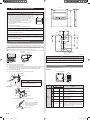
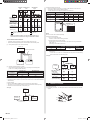
6.1. Wiring system diagram
Connection diagrams
Standard pair:
Indoor
unit side
Power line
Earth (Ground) line
Black
White
Red
*
Control line
Wired remote controller cable
Connection cable to outdoor unit
*Ground the remote controller if it has a earth (ground) wire.
9379127035-02_IM.indb Sec1:79379127035-02_IM.indb Sec1:7 23/01/2013 16:25:4223/01/2013 16:25:42

En-8
Simultaneous twin ( 22, 24 type only )
R
W
B
Wired remote
controller
Indoor unit
(Primary)
Outdoor unit
Remote controller cable
Power line
Bus wire
(Local purchase)
Black
White
Red
Control line
Indoor unit
(Secondary)
Indoor unit
(Primary)
Indoor unit
(Secondary)
Junction box
(Local purchase)
Connection cable
Wired remote controller cable
Wired remote controller is recommended using simultaneous twin or triple connection.
CAUTION
Tighten the indoor unit connection cable and power supply indoor and outdoor unit,
branch box terminal board connections fi rmly with the terminal board screws. Faulty
connection may cause a fi re.
If the indoor unit connection cable and power supply are wired incorrectly, the air
conditioner may be damaged.
Connect the indoor unit connection cable by matching the numbers of the outdoor and
indoor units terminal board numbers as shown in terminal label.
Earth (Ground) both the indoor and outdoor, units by attaching a earth (ground) cable.
Unit shall be grounded in compliance with the country or region's regulations.
CAUTION
Be sure to refer to the above diagram for do correct fi eld wiring. Wrong wiring causes
malfunction of the unit.
Check local electrical rules and also any specifi c wiring instructions or limitation.
6.2. Connection cable preparation
Keep the earth (ground) wire longer than the other wires.
Power supply cable
or connection cable
20 mm
50mm or more
Earth
(ground) wire
Use a 4-core wire cable.
6.3. Connection of wiring
CAUTION
Use care not to mistake the power supply cable and connection wires when installing.
Remove the control box cover and install each connection wire.(1)
Screw
Control box cover
22,24 model(2)
After wiring is complete, secure the remote controller cable, transmission cable, with the
cable tie and the clamper.
Detail (a)
(a)
Wire clamper
(Accessory)
Transmission
cable
Сable tie (Accessory)
Remove excess
after installing
Сable tie (Accessory)
Remove excess after installing
Remote
controller cable
45 mm
Other models(2)
After wiring is complete, secure the remote controller cable, connection cable, and power
supply cable with the cable clamps.
Connection cable
(to outdoor unit)
Cable clamp
Cable clamp
45 mm
Remote control-
ler cable
Install control box cover.(3)
Adjust the position of the screws for control box cover according to the installation.
CAUTION
Do not bundle the remote controller cable, or wire the remote controller cable in paral-
lel, with the indoor unit connection wire (to the outdoor unit) and the power supply
cable. It may cause erroneous operation.
9379127035-02_IM.indb Sec1:89379127035-02_IM.indb Sec1:8 23/01/2013 16:25:4323/01/2013 16:25:43

En-9
.
7. REMOTE CONTROLLER SETTING
CAUTION
When detecting the room temperature using the remote con-
troller, please set up the remote controller according to the
following conditions. If the remote controller is not located prop-
erly, the correct room temperature will not be detected, and
thus abnormal conditions like “not cooled” or “not heated” will
occur even if the air-conditioner is running normally.
• Locate where an average temperature for the room being
air conditioned will be sensed.
• Do not locate directly exposed to the outlet air from the
air-conditioner.
• Locate out of direct sunlight.
• Locate away from the infl uence of other heat sources.
Do not touch the remote controller PC board and PC board parts directly with your hands
.
Do not wire the remote controller cable together with or parallel to the connection
cables, and power supply cable of the INDOOR UNIT and OUTDOOR UNIT, BRANCH
BOX. It may cause erroneous operation.
When installing the bus wire near a source of electromagnetic waves, use shielded wire
.
Do not set the DIP switches, either on the air conditioner or the remote controller, in any
way other than indicated in this manual that is supplied with the air conditioner. Doing
so may result in improper operation.
7.1. Installing the remote controller
Open the operation panel on the front of the remote controller, remove the 2 screws indi-
cated in the following fi gure, and then remove the front case of the remote controller.
When installing the remote controller, remove the connector from the front case. The
wires may break if the connector is not removed and the front case hangs down.
When installing the front case, connect the connector to the front case.
Screws
SET BACK
Front case
(back side)
Rear case
Connector
When remote controller cable is concealed
(1) Conceal the remote controller cable.
(2) Pass the remote controller cable through the hole in the rear case and connect the
remote controller cable to the remote controller terminal board specifi ed in fi gure.
(3) Clamp the remote controller cable sheath with the сable tie as shown in fi gure.
(4) Cut off the excess сable tie.
(5) Install the rear case to the wall, box, etc., with 2 screws fi gure.
Cable tie
(Small)
1. Red
2. White
3. Black
CAUTION
When connecting the remote controller
wires, do not overtighten the screws.
Hole
[Example]
Remote
controller cable
Box
Screws
Connector
Rear case
Ground the remote controller if it has a ground wire.
Wrap the connector and remote
controller wires with vinyl tape
or some other type of insulation
as shown in the fi gure.
Remote controller
Temperature
sensor
30
120
17
120
45.3
33.5
Hole
15.3
23
8
4.5
4.5
4.5 12.5
Hole × 3
Hole × 2
83.5
63.5
6
Unit: mm
CAUTION
Install the remote controller wires so as not to be direct touched with your hand.
Do not touch the remote controller PC board and PC board parts directly with your
hands.
7.2. Setting the DIP switches
Set the remote controller DIP switches.
[Example]
ON
ON
OFF
1
2
3
4
5
6
DIP switch 1
Front case (back side)
NO.
SW state
Detail
OFF ON
DIP-
switch 1
1
★
Cannot be used.
(Do not change)
2
★
Dual remote controller setting
* Refer to "8.4.2. Dual remote controllers."
3
★
Cannot be used.
(Do not change)
4
★
Cannot be used.
(Do not change)
5
★
Cannot be used.
(Do not change)
6
★
Invalidity Validity
Memory backup setting
* Set to ON to use batteries for the memory
backup. If batteries are not used, all of the
settings stored in memory will be deleted if
there is a power failure.
(
★
Factory setting)
9379127035-02_IM.indb Sec1:99379127035-02_IM.indb Sec1:9 23/01/2013 16:25:4323/01/2013 16:25:43

En-10
.
8. FUNCTION SETTING
CAUTION
Confi rm whether the wiring work for outdoor unit has been fi nished.
Confi rm whether the cover for electric control box on the outdoor unit is close.
8.1. Turning on the power
Check the remote controller wiring and DIP switch settings.(1)
Install the front case. (2)
When installing the front case, connect the connector to the front case.
Check the indoor and outdoor unit wiring and circuit board (3)
switch settings, and then turn on the indoor and outdoor units. After “
” has fl ashed
on the set temperature display for several seconds, the clock display will appear in the
center of the remote controller display.
The clock display will appear in the center of the remote controller display.
SU
MO
TU
WE
TH FR
SA
8.2. Function setting
This procedure changes the function settings used to control the indoor unit according to
the installation conditions. Incorrect settings can cause the indoor unit to malfunction. This
procedure should be performed by authorized installation or service personnel only.
Perform the “FUNCTION SETTING” according to the installation conditions using the remote
controller. (Refer to the indoor unit installation manual for details on the function numbers
and setting values.)
(1) Press the SET TEMP. buttons (
) ( ) and FAN button simultaneously for more than
5 seconds to enter the function setting mode.
SU
MO
TU
WE
TH FR
SA
(2) Press the SET BACK button to select the indoor unit number.
SU
MO
TU
WE
TH FR
SA
Unit number of INDOOR UNIT
SET BACK
(3) Press the SET TIME ( ) buttons to select the function number.
Function number
SU
MO
TU
WE
TH FR
SA
(4) Press the SET TEMP. buttons ( ) ( ) to select the setting value.
The display fl ashes as shown to the right during setting value selection.
Setting value
SU
MO
TU
WE
TH FR
SA
(5) Press the TIMER SET button to confi rm the setting.
Press the TIMER SET button for a few seconds until the setting value stops fl ashing.
If the setting value display changes or if “- -” is displayed when the fl ashing stops, the
setting value has not been set correctly.
(An invalid setting value may have been selected for the indoor unit.)
(6) Repeat steps 2 to 5 to perform additional settings.
Press the SET TEMP. buttons (
) ( ) and FAN button simultaneously again for
more than 5 seconds to cancel the function setting mode. In addition, the func-
tion setting mode will be automatically canceled after 1 minute if no operation is
performed.
(7) After completing the FUNCTION SETTING, be sure to turn off the power and turn it on
again.
CAUTION
After turning off the power, wait 30 seconds or more before turning on it again. The
FUNCTION SETTING doesn’t become effective if it doesn’t do so.
• Function Details
(1) Filter Sign
The indoor unit has a sign to inform the user that it is time to clean the fi lter. Select the
time setting for the fi lter sign display interval in the table below according to the amount of
dust or debris in the room. If you do not wish the fi lter sign to be displayed, select the set-
ting value for “No indication”.
(♦... Factory setting)
Setting description
Function
number
Setting value
Standard (2500 hours)
11
00
Long interval (4400 hours) 01
Short interval (1250 hours) 02
♦
No indication 03
(2) Static pressure
Select appropriate static pressure according to the installation conditions.
(♦... Factory setting
)
Setting description
Function
number
Setting value
♦
Normal
21
00
High static pressure 1 01
High static pressure 2 02
High static pressure 3 03
Determine the wind volume in each mode i.e., applicable range of static pressure, refer-
ring to "8.3. Static pressure characteristics." (The unit is factory-set to “00”.)
(3) Cooling room temperature correction
Depending on the installed environment, the room temperature sensor may require a cor-
rection.
The settings may be selected as shown in the table below.
9379127035-02_IM.indb Sec1:109379127035-02_IM.indb Sec1:10 23/01/2013 16:25:4423/01/2013 16:25:44

En-11
(♦... Factory setting)
Setting description
Function
number
Setting value
♦
Standard
30
00
Slightly lower control 01
Lower control 02
Warmer control 03
(4) Heating room temperature correction
Depending on the installed environment, the room temperature sensor
may require a cor-
rection.
The settings may be changed as shown in the table below.
(♦... Factory setting)
Setting description
Function
number
Setting value
♦
Standard
31
00
Lower control 01
Slightly warmer control 02
Warmer control 03
(5) Auto restart
Enable or disable automatic system restart after a power outage.
(♦... Factory setting)
Setting description
Function
number
Setting value
♦
Yes
40
00
No 01
* Auto restart is an emergency function such as for power failure etc. Do not start and stop
the indoor unit by this function in normal operation. Be sure to operate by the control unit,
or external input device.
(6) Indoor room temperature sensor switching function
(Only for Wired remote controller)
The following settings are needed when using the Wired remote controller temperature
sensor.
(♦... Factory setting)
Setting description
Function
number
Setting value
♦
No
42
00
Yes 01
* If setting value is “00” :
Room temperature is controlled by the indoor unit temperature sensor.
* If setting value is “01” :
Room temperature is controlled by either indoor unit temperature sensor or remote
controller unit sensor.
(7) Wireless remote controller signal code
Change the indoor unit Signal Code, depending on the wireless remote controllers.
(♦... Factory setting)
Setting description
Function
number
Setting value
♦
A
44
00
B01
C02
D03
(8) External input control
“Operation/Stop” mode or “Forced stop” mode can be selected.
(♦... Factory setting)
Setting description
Function
number
Setting value
♦
Operation/Stop mode
46
00
(Setting forbidden) 01
Forced stop mode 02
Setting record
•
Record any changes to the settings in the following table.
Setting Setting Value
(1) Filter sign
(2) Static pressure
(3) Cooling room temperature correction
(4) Heating room temperature correction
(5) Auto restart
(6) Indoor room temperature sensor switching func-
tion
(7) Wireless remote controller signal code
(8) External input control
After completing the FUNCTION SETTING, be sure to turn off the power and turn it on
again.
SETTING THE ROOM TEMPERATURE DETECTION
LOCATION
The detection location of the room temperature can be selected from the following 2 examples.
Choose the detection location that is best for the installation location.
A. Indoor unit setting (factory setting)
The room temperature is detected by the indoor unit temperature sensor
.
(1) When the THERMO SENSOR button is pressed, the lock display fl ashes because the
function is locked at the factory.
A
Indoor unit
B. Indoor unit/remote controller setting (room tempera-
ture sensor selection)
The temperature sensor of the indoor unit or the remote controller can be used to detect
the room temperature.
(1) Enable the room temperature sensor selection in FUNCTION SETTING, which will be
previous page.
(2) Press the THERMO SENSOR button for 5 seconds or more to select the temperature
sensor of the indoor unit or the remote controller.
B
Indoor unit
9379127035-02_IM.indb Sec1:119379127035-02_IM.indb Sec1:11 23/01/2013 16:25:4423/01/2013 16:25:44

En-12
CAUTION
1
When select the “Remote controller setting”, if the detected
temperature value between the temperature sensor of the
indoor unit and the temperature sensor of the remote controller
varies signifi cantly, it is likely to return to the control status of
temperature sensor of the indoor unit temporarily.
2
As the temperature sensor of remote controller detects the temperature near the
wall, when there is a certain difference between the room temperature and the wall
temperature, the sensor will not detect the room temperature correctly sometimes.
Especially when the outer side of the wall on which the sensor is positioned is
exposed to the open air, it is recommended to use the temperature sensor of
the indoor unit to detect the room temperature when the indoor and outdoor
temperature difference is signifi cant.
3
The temperature sensor of the remote controller is not only used when there is a
problem in the detection of the temperature sensor of the indoor unit.
NOTE:
If the function to change the temperature sensor is used as shown in examples A (other
than example B), be sure to lock the detection location. If the function is locked, the lock
display
will fl ash when the THERMO SENSOR button is pressed.
8.3. Static pressure characteristic
CAUTION
If the applicable static pressure does not match the static pressure mode, the static
pressure mode maybe changed to another mode automatically.
RECOMMENDED RANGE OF EXTERNAL STATIC PRESSURE [Pa]
30 to 150
1. STATIC PRESSURE MODE
It is necessary to set up a static pressure mode for each usage of static pressure.
Determine the applicable range of static pressure in each mode and wind volume, refer-
ring to the Technical manual.
2. MODE SETTING
It is possible to change the setting of static pressure mode. Refer to "8.2. Function setting."
8.4. Special installation methods
CAUTION
When setting DIP switches, do not touch any other parts on the circuit board directly with
your bare hands.
Be sure to turn off the main power.
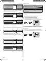
8.4.1. Group control system
A number of indoor units can be operated at the same time using a single remote controller.
(1) Wiring method (indoor unit to remote controller)
123
123
123 123 123
Indoor
unit 1
Bus wire
Remote
controller cable
Remote controller
When ground wire is necessary
Indoor
unit 2
Indoor
unit 3
Indoor
unit 4
(2) DIP switch setting (Indoor unit)
Set the unit number of each indoor unit using the DIP switches on the indoor unit
circuit board. (See the following table and fi gure.)
The DIP switches are normally set to make the unit number 00.
Indoor unit
Unit number
DIP SWITCH No.
1234
1
00 OFF OFF OFF OFF
2
01 ON OFF OFF OFF
3
02 OFF ON OFF OFF
4
03 ON ON OFF OFF
5
04 OFF OFF ON OFF
6
05 ON OFF ON OFF
7
06 OFF ON ON OFF
8
07 ON ON ON OFF
9
08 OFF OFF OFF ON
0
09 ON OFF OFF ON
A
10 OFF ON OFF ON
B
11 ON ON OFF ON
C
12 OFF OFF ON ON
D
13 ON OFF ON ON
E
14 OFF ON ON ON
F
15 ON ON ON ON
Example : unit number 03
ON
1234
NOTE
Be sure to set the unit numbers sequentially.
Remote controller setting(3)
Turn on all of the indoor units.1.
Turn on the indoor unit with the unit number 00 last. (Within 1 minute)
Set the refrigerant circuit address. (Assign the same number to all of the indoor 2.
units connected to an outdoor unit.)
Indoor unit Unit number Function Number Setting Value
1
00
02 00 15
2
01
E
14
F
15
Set the “primary” and “secondary” settings. (Set the indoor unit that is connected to 3.
the outdoor unit using a transmission cable as the “primary”.)
Function Number Setting Value
Primary
51
00
Secondary 01
After completing the function settings, turn off all of the indoor units, and then turn 4.
them back on.
If error code 21, 22, 24, or 27 is displayed, there may be an incorrect setting. *
Perform the remote controller setting again.
NOTES:
• When different indoor unit models are connected using the group control system, some
functions may no longer be available.
• If the group control system contains multiple units that are operated simultaneously, con-
nect and set the units as shown below.
• Auto-changeover operates under the same mode with model unit number 00.
• It should not be connected to any other Gr that is not of the same series (A**G only).
9379127035-02_IM.indb Sec1:129379127035-02_IM.indb Sec1:12 23/01/2013 16:25:4523/01/2013 16:25:45

En-13
Remote
controller
DIP switch setting
(Indoor unit)
Standard
pair
Simultaneous
twin
Simultaneous
triple
Remote controller
setting
Refrigerant circuit
address setting
Out door
unit
Out door
unit
Out door
unit
Indoor
unit
Indoor
unit
Indoor
unit
Indoor
unit
Indoor
unit
Indoor
unit
Unit number
(Function number 02)
Setting value
Setting value
Primary/Secondary setting
(Function number 51)
Transmission cable, Power supply cable
Remote controller cable
Power supply cable
Bus wire
Make sure that the indoor unit with the unit number 00 is
connected to the outdoor unit using a transmission cable.
8.4.2. Dual remote controllers
• 2 separate remote controllers can be used to operate the indoor units.
•
The timer and self-diagnosis functions cannot be used on the secondary units.
(1) Wiring method (indoor unit to remote controller)
Remote controller cable
Indoor unit
Remote controller
Secondary unitPrimary unit
(2) Remote controller DIP switch 1 setting
Set the remote controller DIP switch 1 No. 2 according to the following table.
( Refer to "7.2. Setting the DIP switches.")
Number of remote
controllers
Primary unit Secondary unit
DIP SW 1 No. 2 DIP SW 1 No. 2
1 (Normal) OFF –
2 (Dual) OFF ON
8.4.3. Simultaneous multi-system operation ( 22,24 model )
By combining with an outdoor unit, 2 units for twin indoor units, can be switched ON/OFF •
simultaneously.
Wiring method(1)
Refer to 6.ELECTRICAL WIRING for wiring procedure and wiring method.•
The indoor unit is connected the outdoor unit using a transmission cable is “primary”.•
Connect the remote controller wire to the primary unit.•
Twin type
Outdoor
unit
Indoor
unit
Indoor
unit
Remote
controller
[primary]
[secondary]
DIP switch setting (Indoor unit)(2)
Set the unit number of each indoor unit using the DIP switches on the indoor unit
circuit board. (See the following table and fi gure.)
The DIP switches are normally set to make the unit number 00.
Indoor unit Unit number
DIP SWITCH No.
1234
1
00 OFF OFF OFF OFF
2
01 ON OFF OFF OFF
3
02 OFF ON OFF OFF
DIP switches
Example :
Unit number 02
ON
Circuit board in the control box of indoor unit.
NOTE:
Be sure to set the unit numbers sequentially.
Remote controller setting(3)
Turn on all of the indoor units.1.
Therefore, continue with the setting procedure.
Set the primary and secondary settings.2.
Set the indoor unit that is not connected to the outdoor unit using a transmission
cable as the “01” .
(The setting value is factory-set to “00”.)
Indoor unit Unit number Function Number Setting Value
00
51
00(primary)
01 01(secondary)
After completing the function settings, turn off all of the indoor units, and then turn 3.
them back on.
If error code 21, 22, 24 or 27 is displayed, there may be an incorrect setting. *
Perform the remote controller setting again.
Twin type
Remote
controller
DIP switch setting
(Indoor unit)
Remote controller
setting
Unit number
Unit number
Setting value
(Primary/secondary)
Out door
unit
Indoor
unit
[primary]
Indoor
unit
[secondary]
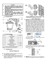
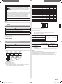
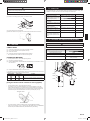
9. FRESH AIR INTAKE
(Processing before use)
When taking in fresh air, cut a slit shaped cabinet in the left side of the outer case with (1)
nippers.
Cut
Cut
Cabinet (iron plate)
9379127035-02_IM.indb Sec1:139379127035-02_IM.indb Sec1:13 23/01/2013 16:25:4523/01/2013 16:25:45

En-14
CAUTION
When removing the cabinet (iron plate), be careful not to damage the indoor unit inter-
nal parts and surrounding area (outer case).
When processing the cabinet (iron plate), be careful not to injure yourself with burrs, etc.
Install the round fl ange (option parts) to the fresh air intake.(2)
Round duct
Connect the duct to the round fl ange.(3)
Seal with a band and vinyl tape, etc. so that air does not leak from the connection.(4)
Duct
10. TEST RUN
CHECK ITEMS
(1) Is operation of each button on the remote controller normal?
(2) Do not air fl ow direction louvers operate normally?
(3) Is the drain normal?
(4)
Is there any abnormal noise and vibration during operation?
• Do not operate the air conditioner in test run for a long time.
[OPERATION METHOD]
• For the operation method, refer to the operating manual.
(1) Stop the air conditioner operation.
(2)
Press the MODE button and the FAN button simultaneously for 2 seconds or more to
start the test run.
Test run display
(3) Press the START/STOP button to stop the test run.
If “C0” appears in the unit number display, there is a remote controller error. Refer to the
installation manual included with the remote controller.
Unit number Error code Content
Incompatible indoor unit is connected
Indoor unit
↔
remote controller communication
error
[Using the wireless remote controller for test run] (Option)
• For the operation method, refer to the operating manual.
•
The outdoor unit may not operate depending on the room temperature. In this case,
press the TEST RUN button on the wireless remote controller while the air conditioner
is running. (Point the transmitter section of the wireless remote controller toward the air
conditioner and press the TEST RUN button with the tip of a ball-point pen, etc.)
Transmitter section
TEST RUN button
•
To end test operation, press the wireless remote controller START/STOP button.
(When the air conditioner is run by pressing the TEST RUN button, the OPERATION
indicator lamp and TIMER indicator lamp will simultaneously fl ash slowly.)
11. CHECK LIST
Pay special attention to the check items below when installing the indoor unit(s). After
installation is complete, be sure to check the following check items again.
CHECK ITEMS If not performed correctly CHECK BOX
Has the indoor unit been
installed correctly?
Vibration, noise, indoor unit may
drop
Has there been a check for gas
leaks (refrigerant pipes)?
No cooling, No heating
Has heat insulation work been
completed?
Water leakage
Does water drain easily from the
indoor units?
Water leakage
Are the wires and pipes all con-
nected completely?
No operation, heat or burn dam-
age
Is the connection cable the
specifi ed thickness?
No operation, heat or burn dam-
age
Are the inlets and outlets free of
any obstacles?
No cooling, No heating
After installation is completed,
has the proper operation and
handling been explained to the
user?
12. OPTIONAL KIT INSTALLATION (OPTION)
WARNING
Regulation of cable differs from each locality, refer in accordance with local rules.
This air conditioner can be connected with the following optional kits.
Option type Connector No.
UTY-XSZX (Remote sensor unit) CN8
UTD-ECS5A (External input) CN102
UTD-ECS5A (External output) CN103
UTZ-PX1NBA (Drain pump unit)
CN106 ( Drain pump )
CN9 ( Float SW )
CN103
CN102
CN106
CN8
CN9
9379127035-02_IM.indb Sec1:149379127035-02_IM.indb Sec1:14 23/01/2013 16:25:4623/01/2013 16:25:46

En-15
13. CUSTOMER GUIDANCE
Explain the following to the customer in accordance with the operating manual:
(1) Starting and stopping method, operation switching, temperature adjustment, timer, air
fl ow switching, and other remote controller operations.
(
2) Air fi lter removal and cleaning, and how to use the air louvers.
(3) Give the operating and installation manuals to the customer.
(4) If the signal code is changed, explain to the customer how it changed (the system
returns to signal code A when the batteries in the remote controller are replaced).
*(4) is applicable to using wireless remote controller.
14. ERROR CODES
If you use a wired type remote controller, error codes will appear on the remote control-
ler display. If you use a wireless remote controller, the lamps on the IR receiver unit will
output error codes by way of blinking patterns. See the lamp blinking patterns and error
codes in the table below. An error display is displayed only during operation.
Error display
Wired
remote con-
troller Error
code
Description
OPERATION
lamp
(green)
TIMER
lamp
(orange)
ECONOMY
lamp
(green)
●
(1)
●
(1)
◊
Serial communication error
●
(1)
●
(2)
◊
Wired remote controller
communication error
●
(1)
●
(5)
◊
Check run unfi nished
●
(2)
●
(1)
◊
Unit number or Refrigerant circuit
address setting error
[Simultaneous Multi]
●
(2)
●
(2)
◊
Indoor unit capacity error
●
(2)
●
(3)
◊
Combination error
●
(2)
●
(4)
◊
Connection unit number •
error (indoor secondary unit)
[Simultaneous Multi]
Connection unit number error •
(indoor unit or branch unit)
[Flexible Multi]
●
(2)
●
(7)
◊
Primary unit, secondary unit setup
error [Simultaneous Multi]
●
(3)
●
(1)
◊
Power supply interruption error
●
(3)
●
(2)
◊
Indoor unit PCB model
information error
●
(3)
●
(5)
◊
Manual auto switch error
●
(4)
●
(1)
◊
Room temp. sensor error
●
(4)
●
(2)
◊
Indoor unit Heat Ex. Middle temp.
sensor error
●
(5)
●
(1)
◊
Indoor unit fan motor error
●
(5)
●
(3)
◊
Drain pump error
●
(5)
●
(7)
◊
Damper error
●
(5)
●
(15)
◊
Indoor unit error
●
(6)
●
(2)
◊
Outdoor unit main PCB model
information error or
communication error
●
(6)
●
(3)
◊
Inverter error
●
(6)
●
(4)
◊
Active fi lter error, PFC circuit error
●
(6)
●
(5)
◊
Trip terminal L error
●
(6)
●
(10)
◊
Display PCB microcomputers
communication error
●
(7)
●
(1)
◊
Discharge temp. sensor error
●
(7)
●
(2)
◊
Compressor temp. sensor error
Error display
Wired
remote con-
troller Error
code
Description
OPERATION
lamp
(green)
TIMER
lamp
(orange)
ECONOMY
lamp
(green)
●
(7)
●
(3)
◊
Outdoor unit Heat Ex. liquid temp.
sensor error
●
(7)
●
(4)
◊
Outdoor temp. sensor error
●
(7)
●
(5)
◊
Suction Gas temp. sensor error
●
(7)
●
(6)
◊
2-way valve temp. sensor error•
3-way valve temp. sensor error•
●
(7)
●
(7)
◊
Heat sink temp. sensor error
●
(8)
●
(2)
◊
Sub-cool Heat Ex. gas inlet •
temp. sensor error
Sub-cool Heat Ex. gas outlet •
temp. sensor error
●
(8)
●
(3)
◊
Liquid pipe temp. sensor error
●
(8)
●
(4)
◊
Current sensor error
●
(8)
●
(6)
◊
Discharge pressure sensor error•
Suction pressure sensor error•
High pressure switch error•
●
(9)
●
(4)
◊
Trip detection
●
(9)
●
(5)
◊
Compressor rotor position
detection error (permanent stop)
●
(9)
●
(7)
◊
Outdoor unit fan motor 1 error
●
(9)
●
(8)
◊
Outdoor unit fan motor 2 error
●
(9)
●
(9)
◊
4-way valve error
●
(9)
●
(10)
◊
Coil (expansion valve ) error
●
(10)
●
(1)
◊
Discharge temp. error
●
(10)
●
(3)
◊
Compressor temp. error
●
(10)
●
(4)
◊
High pressure error
●
(10)
●
(5)
◊
Low pressure error
●
(13)
●
(2)
◊
Branch boxes error
[Flexible Multi]
Display mode
●
: 0.5s ON / 0.5s OFF
◊
: 0.1s ON / 0.1s OFF
( ) : Number of fl ashing
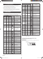
[Troubleshooting at the remote controller LCD]
This is possible only on the wired remote controller.
[Self-diagnosis]
If an error occurs, the following display will be shown. (“Er” will appear in the set room
temperature display.)
Unit number
of indoor unit
Error code
EX. Self-diagnosis
9379127035-02_IM.indb Sec1:159379127035-02_IM.indb Sec1:15 23/01/2013 16:25:4623/01/2013 16:25:46
-
 1
1
-
 2
2
-
 3
3
-
 4
4
-
 5
5
-
 6
6
-
 7
7
-
 8
8
-
 9
9
-
 10
10
-
 11
11
-
 12
12
-
 13
13
-
 14
14
-
 15
15
-
 16
16


Fujitsu ARYG24LMLA Installation guide
- Category
- Split-system air conditioners
- Type
- Installation guide
Ask a question and I''ll find the answer in the document
Finding information in a document is now easier with AI
Related papers
-
Fujitsu HRG45LHTA Installation guide
-
-
Fujitsu ARXA36GBLH Installation guide
-
Fujitsu ARXN018GLBH Installation guide
-
Fujitsu ARXP018GLAH Installation guide
-
-
Fujitsu ARXH054GTAH Installation guide
-
-
Fujitsu ARXC45GATH Installation guide
-
Fujitsu ARXN30GATH Installation guide