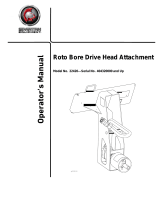
Toro Bore Drive Head is a hydraulically powered auger attachment designed for vertical hole digging in earth, enabling easy installation of posts, plants, and other items for construction and landscaping.

FormNo.3420-680RevA
BoreDriveHeadAttachment
CompactToolCarrier
ModelNo.22420—SerialNo.402000000andUp
g029193
Registeratwww.Toro.com.
OriginalInstructions(EN)
*3420-680*A

ThisproductcomplieswithallrelevantEuropean
directives.Fordetails,pleaseseetheDeclarationof
Incorporation(DOI)atthebackofthispublication.
WARNING
CALIFORNIA
Proposition65Warning
Useofthisproductmaycauseexposure
tochemicalsknowntotheStateof
Californiatocausecancer,birthdefects,
orotherreproductiveharm.
Introduction
Themachineisahydraulicallypoweredauger
attachmentforTorocompacttoolcarriers.Itis
designedtodigverticalholesinearthforthe
installationofposts,plants,andotherconstruction
andlandscapingneeds.Itisnotintendedtodrillholes
inpavement,concrete,orice.
Readthisinformationcarefullytolearnhowtooperate
andmaintainyourproductproperlyandtoavoid
injuryandproductdamage.Youareresponsiblefor
operatingtheproductproperlyandsafely.
YoumaycontactT orodirectlyatwww.T oro.com
forproductsafetyandoperationtrainingmaterials,
accessoryinformation,helpndingadealer,orto
registeryourproduct.
Wheneveryouneedservice,genuineT oroparts,or
additionalinformation,contactanAuthorizedService
DealerorT oroCustomerServiceandhavethemodel
andserialnumbersofyourproductready.Figure1
identiesthelocationofthemodelandserialnumbers
ontheproduct.Writethenumbersinthespace
provided.
Important:Withyourmobiledevice,youcan
scantheQRcodeontheserialnumberdecal(if
equipped)toaccesswarranty,parts,andother
productinformation.
g257161
Figure1
1.Modelandserialnumberlocation
ModelNo.
SerialNo.
Thismanualidentiespotentialhazardsandhas
safetymessagesidentiedbythesafety-alertsymbol
(Figure2),whichsignalsahazardthatmaycause
seriousinjuryordeathifyoudonotfollowthe
recommendedprecautions.
g000502
Figure2
1.Safety-alertsymbol
Thismanualuses2wordstohighlightinformation.
Importantcallsattentiontospecialmechanical
informationandNoteemphasizesgeneralinformation
worthyofspecialattention.
©2018—TheToro®Company
8111LyndaleAvenueSouth
Bloomington,MN55420
2
Contactusatwww.Toro.com.
PrintedintheUSA
AllRightsReserved

Contents
Safety.......................................................................3
GeneralSafety...................................................3
SlopeSafety.......................................................4
BoringUnitSafety...............................................4
MaintenanceandStorageSafety........................4
SafetyandInstructionalDecals..........................5
ProductOverview.....................................................5
Specications....................................................5
Attachments/Accessories...................................5
Operation..................................................................6
InstallingandRemovingtheAttachment.............6
InstallinganAccessory.......................................6
RemovinganAccessory.....................................7
UsingtheBoringUnit..........................................7
TransportPosition..............................................8
Storage.....................................................................9
Troubleshooting......................................................10
Safety
DANGER
Theremaybeburiedutilitylinesinthework
area.Diggingintothemmaycauseashock
oranexplosion.
Havethepropertyorworkareamarkedfor
buriedlinesanddonotdiginmarkedareas.
Contactyourlocalmarkingserviceorutility
companytohavethepropertymarked(for
example,intheUS,call811orinAustralia,
call1100forthenationwidemarkingservice).
GeneralSafety
Alwaysfollowallsafetyinstructionstoavoidserious
injuryordeath.
•Alwayscarrytheattachmentclosetotheground;
refertoTransportPosition(page8).
•Havethepropertyorworkareamarkedforburied
linesandotherobjects,anddonotdiginmarked
areas.
•ReadandunderstandthecontentofthisOperator’s
Manualbeforestartingtheengine.
•Useyourfullattentionwhileoperatingthe
machine.Donotengageinanyactivitythat
causesdistractions;otherwise,injuryorproperty
damagemayoccur.
•Neverallowchildrenoruntrainedpeopleto
operatethemachine.
•Keepyourhandsandfeetawayfromthemoving
componentsandattachments.
•Donotoperatethemachinewithouttheguards
andothersafetyprotectivedevicesinplaceand
workingonthemachine.
•Keepbystandersandpetsasafedistanceaway
fromthemachine.
•Stopthemachine,shutofftheengine,andremove
thekeybeforeservicing,fueling,orunclogging
themachine.
Improperlyusingormaintainingthismachinecan
resultininjury.Toreducethepotentialforinjury,
complywiththesesafetyinstructionsandalways
payattentiontothesafety-alertsymbol
,which
meansCaution,Warning,orDanger—personalsafety
instruction.Failuretocomplywiththeseinstructions
mayresultinpersonalinjuryordeath.
Youcanndadditionalsafetyinformationwhere
neededthroughoutthisOperator’sManual.
3

SlopeSafety
•Operatethemachineupanddownslopeswith
theheavyendofthemachineuphill.Weight
distributionchangeswithattachments.Anempty
attachmentmakestherearofthemachinethe
heavyend,andafullattachmentmakesthe
frontofthemachinetheheavyend.Mostother
attachmentsmakethefrontofmachinetheheavy
end.
•Keeptheattachmentintheloweredposition
whenonslopes.Raisingtheattachmentona
slopeaffectsthestabilityofthemachine.
•Slopesareamajorfactorrelatedtolossofcontrol
andtip-overaccidents,whichcanresultinsevere
injuryordeath.Operatingthemachineonany
slopeoruneventerrainrequiresextracaution.
•Establishyourownproceduresandrulesfor
operatingonslopes.Theseproceduresmust
includesurveyingthesitetodeterminewhich
slopesaresafeformachineoperation.Always
usecommonsenseandgoodjudgmentwhen
performingthissurvey.
•Slowdownanduseextracareonhillsides.Ground
conditionscanaffectthestabilityofthemachine.
•Avoidstartingorstoppingonaslope.Ifthe
machinelosestraction,proceedslowly,straight
downtheslope.
•Avoidturningonslopes.Ifyoumustturn,turn
slowlyandkeeptheheavyendofthemachine
uphill.
•Keepallmovementsonslopesslowandgradual.
Donotmakesuddenchangesinspeedor
direction.
•Ifyoufeeluneasyoperatingthemachineona
slope,donotdoit.
•Watchforholes,ruts,orbumps,asuneventerrain
couldoverturnthemachine.Tallgrasscanhide
obstacles.
•Usecautionwhenoperatingonwetsurfaces.
Reducedtractioncouldcausesliding.
•Donotoperatethemachineneardrop-offs,
ditches,embankments,orbodiesofwater.The
machinecouldsuddenlyrolloverifawheelor
trackgoesovertheedgeortheedgecavesin.
Maintainasafedistancebetweenthemachine
andanyhazard.
•Donotremoveoraddattachmentsonaslope.
•Donotparkthemachineonahillsideorslope.
•Donotpullatraileronanyslope.
BoringUnitSafety
•Forwheeledmachines,donotusethe
counterweightonthetractionunitwhenusingthe
boringunit.
•Keepatleasttenfeetfromrotatingparts,unless
youareoperatingtherodguidetool.
•Donotwearlooseclothingorjewelrywhile
operatingorassistingwiththeboringunit.
•Neveruseanythingbuttherodguidetoolfor
startingtherodandboringbit.
•Neveruseboltsorpinsinplaceofpushbutton
connectors.
•Alwayshave2peopleoperatetheattachment,1
tooperatethetractionunitandtheothertoguide
theboringunitwiththeguidetool.
•Alwaysusetheguidetooltoaligntheboringunit.
•Neverstraddleorstandontherodwhenthe
engineisrunning.
MaintenanceandStorage
Safety
•Checkfastenersatfrequentintervalsforproper
tightnesstoensurethattheequipmentisinsafe
operatingcondition.
•RefertotheOperator’sManualforimportant
detailsifyoustoretheattachmentforanextended
periodoftime
•Maintainorreplacesafetyandinstructionlabels,
asnecessary.
4

SafetyandInstructionalDecals
Safetydecalsandinstructionsareeasilyvisibletotheoperatorandarelocatednearanyarea
ofpotentialdanger.Replaceanydecalthatisdamagedormissing.
decal99-9945
99-9945
1.Warning—readthe
Operator’sManual.
3.Explosionandelectric
shockhazard—donotdig
inareaswithburiedgas
orelectricallines;contact
localpowerorganizations
beforedigging.
2.Entanglementhazard,
shaft—keepbystanders
asafedistancefromthe
machine.
ProductOverview
Specications
Note:Specicationsanddesignaresubjectto
changewithoutnotice.
Width
61cm(24inches)
Length
56cm(22inches)
Height
63.5cm(25inches)
Weight
54kg(120lb)
Boringdiameter
3.2to8.9cm(1.25to3.5
inches)
Attachments/Accessories
AselectionofT oroapprovedattachmentsand
accessoriesisavailableforusewiththemachine
toenhanceandexpanditscapabilities.Contact
yourAuthorizedServiceDealerorauthorizedToro
distributororgotowww.T oro.comforalistofall
approvedattachmentsandaccessories.
Toensureoptimumperformanceandcontinuedsafety
certicationofthemachine,useonlygenuineT oro
replacementpartsandaccessories.Replacement
partsandaccessoriesmadebyothermanufacturers
couldbedangerous,andsuchusecouldvoidthe
productwarranty.
5

Operation
InstallingandRemoving
theAttachment
RefertotheOperator’sManualforthetractionunitfor
theinstallationandremovalprocedure.
Important:Beforeinstallingtheattachment,
positionthemachineonalevelsurface,ensure
thatthemountplatesarefreeofanydirtordebris,
andensurethatthepinsrotatefreely.Ifthepins
donotrotatefreely,greasethem.
Note:Alwaysusethetractionunittoliftandmove
theattachment.
WARNING
Ifyoudonotfullyseatthequick-attach
pinsthroughtheattachmentmountplate,
theattachmentcouldfalloffthemachine,
crushingyouorbystanders.
Ensurethatthequick-attachpinsarefully
seatedintheattachmentmountplate.
WARNING
Hydraulicuidescapingunderpressurecan
penetrateskinandcauseinjury.Fluidinjected
intotheskinmustbesurgicallyremoved
withinafewhoursbyadoctorfamiliarwith
thisformofinjury;otherwise,gangrenemay
result.
•Ensurethatallhydraulic-uidhoses
andlinesareingoodconditionandall
hydraulicconnectionsandttingsaretight
beforeapplyingpressuretothehydraulic
system.
•Keepyourbodyandhandsawayfrom
pinholeleaksornozzlesthateject
high-pressurehydraulicuid.
•Usecardboardorpapertondhydraulic
leaks;neveruseyourhands.
CAUTION
Hydrauliccouplers,hydrauliclines/valves,
andhydraulicuidmaybehot.Ifyoucontact
hotcomponents,youmaybeburned.
•Weargloveswhenoperatingthehydraulic
couplers.
•Allowthemachinetocoolbeforetouching
hydrauliccomponents.
•Donottouchhydraulicuidspills.
InstallinganAccessory
Severaldifferentrodsandbitsareavailableforuse
withtheattachment.ContactyourAuthorizedService
Dealer.
1.Parkthemachineonalevelsurface,lowerthe
loaderarms,andengagetheparkingbrake(if
applicable).
2.Shutofftheengine,removethekey,andwaitfor
allmovingpartstostop.
3.Slidethehexshaftofarod,boringbit,orreamer
intothesocket.Aligntheholeinthesocketwith
thepushbuttonconnector(Figure3).
g008475
Figure3
1.Accessoryshaft
3.Pushbuttonconnector
2.Socket
4.Hole
4.Pressdownthepushbuttonconnectorandpush
theshaftintothesocketuntiltheconnector
snapsintotheholeinthesocket(Figure3).
5.Repeatsteps3and4.
6

RemovinganAccessory
1.Parkthemachineonalevelsurface,lowerthe
loaderarms,andengagetheparkingbrake(if
applicable).
2.Shutofftheengine,removethekey,andwaitfor
allmovingpartstostop.
3.Pressthepushbuttonconnectorsecuringthe
accessoryshaftinthesocketandpullthe
accessoryfreeofthesocket.
UsingtheBoringUnit
DiggingaTrench
Beforedrillingunderawalkordriveway,youmust
makeanentranceandanexittrenchoneithersideof
thedrillingarea(Figure4).
•Bothtrenchesmustbeatleast15cm(6inch)wide
and46cm(18inches)deep.
•Theentrancetrenchmustbeatleast2.13m(7ft)
longandperpendiculartothewalkordriveway.
•Theexittrenchmustbeatleast0.91m(3ft)to1.8
m(6ft)long,paralleltothewalkordriveway,and
centeredacrossfromtheentrancetrench.
g008476
Figure4
1.Entrancetrench3.Exittrench
2.Sidewalk
BoringaHole
Important:Boringisa2-personoperation.Do
notattempttoperformthisoperationbyyourself.
1.Positionthetractionunitwiththedriveheadat
thebeginningofthetrenchandlowerittothe
appropriatedepth.
2.Shutofftheengine,removethekey,andwaitfor
allmovingpartstostop.
3.Connectarodandboringbitontothedrivehead.
4.Connecttherodguidetooltotherodjustbehind
theboringbit(Figure5).
g008477
Figure5
1.Sidewalkordriveway
4.Rod
2.Entrancetrench5.Rod-guidetool
3.Boringbit
5.Withthepersonguidingtheboringbitpositioned
totherightofthetrench(Figure5),startthe
engine,movethepumpselectorvalvetothe
SLOWposition(200and300seriestractionunits
only),movethethrottletomidwaybetweenthe
SLOWandFASTpositions,andpulltheauxiliary
hydraulicsleverrearwardtostarttheforward
rotationoftheboringbit.
6.Slowlymovethetractionunitforward,whilethe
personwiththerod-guidetoolguidestheboring
bitintothesoil(Figure5).
7.Oncetheentiredrillbitisinthesoil,pushthe
auxiliaryhydraulicsleverintoneutral.
8.Shutofftheengine,removethekey,andwaitfor
allmovingpartstostop.
9.Iftherodisnotwithinthegradetolerancesfor
thejobbeingperformed,starttheengineand
drivebackwardtopulltheboringbitoutofthe
soil,thenrepeatsteps5through8,making
adjustmentstocorrectthegrade.
10.Removetherod-guidetool.
11.Starttheengineandpulltheauxiliaryhydraulics
leverrearwardtostarttheboringbit.
7

12.Slowlymovethetractionunitforwardasthe
boringbitdigsintothesoil.
Important:Donotdrivetoofast,forcingthe
bitintothesoil.Allowthebittoprogress
atitsownrate.Neverpushorpullthebit
throughthesoilwhenthedriveheadisnot
turning.
13.Whenabout15cm(6inches)ofrodareleft
showingintheentrancetrenchorwhenthe
boringbitcompletelyentersandboresintothe
farsideoftheexittrench,stopthetractionunit,
pushtheauxiliaryhydraulicsleverintoneutral,
shutofftheengine,andremovethekey.
14.Iftheboringbithasnotyetenteredtheexit
trench,completethefollowing:
A.Detachtherodfromthedrivehead.
B.Starttheengineandbackuptotheendof
theentrancetrench.
C.Shutofftheengine,removethekey,and
waitforallmovingpartstostop.
D.Connectanotherrodandrepeatsteps11
through14.
ReamingtheHole
1.Usingashovel,carefullydigaroundtheboring
bit,clearingitofsoiluntilyoucanremovethe
bit(Figure6).
g008478
Figure6
1.Sidewalkordriveway
4.Reamer
2.Exittrench
5.Swivel
3.Shoveldug-outarea
aroundbit
2.Removetheboringbitandattachthereamer
(Figure6).
3.Attachthecableorpipingbeinginstalledtothe
swivelontheendofthereamer(Figure6).
4.Starttheengineandpulltheauxiliaryhydraulics
leverrearwardtostartthereamer.
5.Slowlymovethetractionunitrearwardasthe
reamerdigsintothesoil.
Important:Donotdrivetoofast,forcing
thereamerintothesoil.Allowthereamerto
progressatitsownrate.Neverpushorpull
thereamerthroughthesoilwhenthedrive
headisnotturning.
6.Whenarodcouplingisabout15cm(6inches)
intotheentrancetrenchorwhenthereamer
completelyentersthetrenchwithabout15cm(6
inches)ofthecableorpiping,stopthetraction
unit,pulltheauxiliaryhydraulicsleverinto
neutral,shutofftheengine,andremovethekey.
7.Ifthereamerhasnotyetenteredtheexittrench,
completethefollowing:
A.Detachtherodfromthedriveheadandrod
stillinthesoil.
B.Starttheengineandmovetothefrontof
theentrancetrench.
C.Shutofftheengine,removethekey,and
waitforallmovingpartstostop.
D.Connectthedriveheadtotherodshaftin
thesoil.
E.Repeatsteps4through7.
8.Withthereamerandcable/pipingintheentrance
trench,removethecableorpipingfromthe
reamer.
TransportPosition
Whentransportingtheattachment,raisetheloader
armsslightly,nomorethan15cm(6inches)above
thelowestposition.Tilttheattachmentsothatthe
attachmentplateisvertical.
g257693
Figure7
1.Nomorethan15cm(6
inches)abovethelowest
position
2.Attachmentplateis
vertical.
8

Storage
1.Beforelong-termstorage,washtheattachment
withmilddetergentandwatertoremovedirtand
grime.
2.Checktheconditionoftheteeth.Turnorreplace
anywornordamagedteeth.
3.Checkandtightenallbolts,nuts,andscrews.
Repairorreplaceanydamagedorwornpart.
4.Ensurethatallhydrauliccouplersareconnected
togethertopreventcontaminationofthe
hydraulicsystem.
5.Paintallscratchedorbaremetalsurfaces.Paint
isavailablefromyourAuthorizedServiceDealer.
6.Storetheattachmentinaclean,drygarageor
storagearea.Coverittoprotectitandkeepit
clean.
9

Troubleshooting
Problem
PossibleCauseCorrectiveAction
1.Thehydrauliccouplerisnotcompletely
connected.
1.Checkandtightenallcouplers.
2.Ahydrauliccouplerisdamaged.
2.Checkthecouplersandreplaceany
thataredamaged.
3.Thereisanobstructioninahydraulic
hose.
3.Findandremovetheobstruction.
4.Ahydraulichoseiskinked.4.Replacethekinkedhose.
5.Theauxiliaryvalveonthetractionunit
isnotopening.
5.Repairthevalve.
Theboredriveheaddoesnotrotate.
6.Ahydraulicmotorisdamagedorworn.6.Replaceorrepairthemotor.
10

DeclarationofIncorporation
TheToroCompany,8111LyndaleAvenueSouth,Bloomington,MN,USAdeclaresthatthefollowingunit(s)
conform(s)tothedirectiveslisted,wheninstalledinaccordancewiththeaccompanyinginstructionsontocertain
ToromodelsasindicatedontherelevantDeclarationsofConformity.
ModelNo.
SerialNo.
ProductDescriptionInvoiceDescription
GeneralDescription
Directive
22420402000000andUpBoreDriveHeadAttachment
BOREDRIVEHEAD
ATTACHMENTCE
CompactUtilityLoader2006/42/EC
RelevanttechnicaldocumentationhasbeencompiledasrequiredperPartBofAnnexVIIof2006/42/EC.
Wewillundertaketotransmit,inresponsetorequestsbynationalauthorities,relevantinformationonthispartly
completedmachinery.Themethodoftransmissionshallbeelectronictransmittal.
ThismachineryshallnotbeputintoserviceuntilincorporatedintoapprovedToromodelsasindicatedonthe
associatedDeclarationofConformityandinaccordancewithallinstructions,wherebyitcanbedeclaredin
conformitywithallrelevantDirectives.
Certied:
AuthorizedRepresentative:
MarcelDutrieux
ManagerEuropeanProductIntegrity
ToroEuropeNV
Nijverheidsstraat5
2260Oevel
Belgium
JoeHager
Sr.EngineeringManager
Tel.+3216386659
8111LyndaleAve.South
Bloomington,MN55420,USA
July2,2018

EuropeanPrivacyNotice
TheInformationT oroCollects
ToroWarrantyCompany(T oro)respectsyourprivacy.Inordertoprocessyourwarrantyclaimandcontactyouintheeventofaproductrecall,weaskyou
tosharecertainpersonalinformationwithus,eitherdirectlyorthroughyourlocalT orocompanyordealer.
TheT orowarrantysystemishostedonserverslocatedwithintheUnitedStateswhereprivacylawmaynotprovidethesameprotectionasapplies
inyourcountry.
BYSHARINGYOURPERSONALINFORMATIONWITHUS,YOUARECONSENTINGTOTHEPROCESSINGOFYOURPERSONALINFORMATION
ASDESCRIBEDINTHISPRIVACYNOTICE.
TheWayT oroUsesInformation
Toromayuseyourpersonalinformationtoprocesswarrantyclaims,tocontactyouintheeventofaproductrecallandforanyotherpurposewhichwetell
youabout.T oromayshareyourinformationwithToro'safliates,dealersorotherbusinesspartnersinconnectionwithanyoftheseactivities.Wewillnot
sellyourpersonalinformationtoanyothercompany.Wereservetherighttodisclosepersonalinformationinordertocomplywithapplicablelawsand
withrequestsbytheappropriateauthorities,tooperateoursystemsproperlyorforourownprotectionorthatofotherusers.
RetentionofyourPersonalInformation
Wewillkeepyourpersonalinformationaslongasweneeditforthepurposesforwhichitwasoriginallycollectedorforotherlegitimatepurposes
(suchasregulatorycompliance),orasrequiredbyapplicablelaw.
Toro'sCommitmenttoSecurityofY ourPersonalInformation
Wetakereasonableprecautionsinordertoprotectthesecurityofyourpersonalinformation.Wealsotakestepstomaintaintheaccuracyandcurrent
statusofpersonalinformation.
AccessandCorrectionofyourPersonalInformation
Ifyouwouldliketorevieworcorrectyourpersonalinformation,pleasecontactusbyemailat[email protected].
AustralianConsumerLaw
AustraliancustomerswillnddetailsrelatingtotheAustralianConsumerLaweitherinsidetheboxoratyourlocalToroDealer.
374-0282RevC
-
 1
1
-
 2
2
-
 3
3
-
 4
4
-
 5
5
-
 6
6
-
 7
7
-
 8
8
-
 9
9
-
 10
10
-
 11
11
-
 12
12
Toro Bore Drive Head User manual
- Type
- User manual
- This manual is also suitable for
Toro Bore Drive Head is a hydraulically powered auger attachment designed for vertical hole digging in earth, enabling easy installation of posts, plants, and other items for construction and landscaping.
Ask a question and I''ll find the answer in the document
Finding information in a document is now easier with AI
Related papers
-
Toro Bore Drive Head Attachment, Compact Tool Carrier User manual
-
Toro Bore Drive Head Attachment, Compact Tool Carrier User manual
-
Toro Bore Drive Head User manual
-
Toro Bore Drive Head Attachment, Dingo Compact Utility Loader User manual
-
Toro Leveler, Compact Tool Carriers User manual
-
Toro 22414 User manual
-
Toro Trench Filler, Compact Utility Loader User manual
-
Toro Trench Filler User manual
-
Toro Auger Head, TX 413 Compact Utility Loaders User manual
-
Toro Hydra Borer, Pro Sneak 360 Vibratory Plow User manual


