Page is loading ...

INSTALLATION
MANUAL
Remote Control Vehicle Starter
Models: CS101RS
CS102RS
R
© Copyright 1996 Magnadyne Corp.
This device complies with part 15 of the FCC rules.
Operation is subject to the following two conditions:
(1) This device may not cause harmful interference; and
(2) This device must accept any interference received,
including interference that may cause undesired
operation.
Note: The manufacturer is not responsible for any radio
or TV interference caused by unauthorized
modifications to this equipment. Such modifications
could void the user’s authority to operate the
equipment.

Congratulations
On your purchase of this unique remote control vehicle starter. This vehicle starter is designed
and assembled to rigid quality standards, using state of the art components. Please read the
operation instructions to insure you enjoy the maximum benefits available.
2
●
Depress the remote start button on the transmitter for approximately (2) seconds and release.
The system will activate and go thru a safety check before starting the vehicle’s engine.
●
This system duplicates operation of the vehicles ignition switch without using keys or unlocking
the steering wheel.
●
During cranking, the system activates the ignition and starter circuits and counts the RPM’s.
Upon proper RPM’s, the starter is released immediately and the engine is running on remote
control. Once the engine is running, additional circuits to the fuse panel will activate, to turn on
your preset climate controls.
●
The engine will run for approximately 12 minutes to pre-warm the engine and to pre-warm or
pre-cool the interior. If desired the engine can also be programmed to run for 6 or 24 minutes.
●
If the engine refuses to start, the vehicle starter will turn off to prevent excessive battery drain.
●
If the engine starts and then stalls, the system will automatically restart the engine.
●
To operate the vehicle before the normal run time expires, just enter the vehicle as usual, insert
the ignition key (to unlock the steering column) and drive off. Upon the first application of the
brake pedal, the vehicle starter turns off.
Note: If the brake pedal is depressed before the ignition key is turned on, the system will turn
off. Simply restart the engine with the ignition key and drive off.
●
If desired, the system may be turned off by depressing the transmitter button again.
●
Some up-scale vehicles have a timed retained accessory power circuit. The “RAP” circuit allows
most of the vehicle’s accessories (radio, power windows and roof, etc.) to operate after the
ignition key is turned off. The RAP circuit usually lasts for 10 minutes or until a door is opened,
therefore, when the vehicle starter turns off, the radio will continue to play on GM vehicle’s (if
turned on) for 10 minutes or until a door is opened.
Information Note: If the vehicle has time delayed headlights, the lights will turn off after the
delay.
CS102RS Only (Options)
●
Depress the door lock/unlock button (button #1) on the transmitter to remotely lock and unlock
the factory power door locks.
●
Depress both buttons on the transmitter to activate an optional accessory (trunk release, power
windows, etc.). This is the 3rd transmitter channel.
Operation
Safety Features
To prevent bodily harm, vehicle damage, or attempted theft, the vehicle starter will turn off if:
●
Fuse is removed, hood is raised, brake pedal is depressed, engine refused to start.
●
Upon expiration of the warm up time or, optional on/off switch is off.

Warnings!
1.
This unit is designed for fuel injected gasoline or diesel vehicles with an automatic transmission
only.
2. Never install this unit on a vehicle with a manual transmission.
3. Always apply the emergency brake and lock the vehicle as you exit.
4. Keep transmitter[s] out of children’s reach.
5. This system does not violate national highway safety standards, however some areas may have
local ordinances that prohibit leaving a vehicle unattended on public streets.
6. Do not leave anyone in the vehicle while running on remote control.
7. Alert service personnel that the vehicle can be started automatically and to disconnect fuse.
8. The use, maintaining, and operations of this system is the sole responsibility of the owner.
9. Should the unit malfunction, disconnect the fuse until the problem is corrected.
10. Do not use in an enclosed area or garage.
11. Do not install the ECM (control module) under the hood or any place that water could enter
the ECM.
1. On vehicles equipped with SRS air bag restraint, Do Not Probe Any Wires of the Restraint
System as this could cause the air bag to inflate. The wires are usually identified with a label.
2. Do not install this system on 1988+ Jaguar XJ6 or any vehicle that switches low voltage
through the ignition switch.
3. Use a voltmeter to verify wire functions and that the ignition switch is switching [+] 12 volts
while rotating the ignition switch.
4. We have made every effort to list proper vehicle wire colors, use the color codes as a guide
only. It is the installers responsibility to insure the correct vehicle starter wires are connected to
the correct vehicle wires.
5. Do not install components near the steering linkage, gas or brake pedal.
6. For best connection, we recommend soldering.
7. Using a connector that’s to big will result in a faulty connection and a dissatisfied customer.
3
Off
On
Start
Lock
Acc
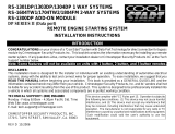
Ignition Switch Operation and Location
●
A typical ignition switch has heavier gauge wires for B+, Ignition,
Starter, and Accessory circuits.
●
When the ignition key is turned to start, power is applied only to
the starter and ignition wires.
●
When the key is released, the ignition wire remains hot and the
accessory wire(s) will then go hot.
Installation and Wire Connection Warnings!
●
This system taps onto the same wires the ignition switch is connected to.
●
Ford and import vehicle’s (except Ford 150 Vans), the ignition switch is inside the steering
column at the lock cylinder.
●
On GM and most other vehicles including Ford 150 vans, the ignition switch is under the dash
on the top side of steering column, about 2ft. from the fire wall (a rod on top side of steering
column connects the key lock cylinder to the ignition switch.)
●
Remove trim as necessary and physically locate the vehicles ignition switch and wiring.

Wire Colors, Function and Installation
White 4-Pin Connector:
Orange Wire: (Starter Output)
Sends out (+)12 volts while cranking by remote control. Sends power to the vehicle’s park-
neutral safety switch to engage the starter solenoid. Connect to the vehicle’s starter wire that
goes hot in the start only position.
Yellow Wire: (Ignition Output)
Sends out (+)12 volts while cranking and running on remote control. This is the vehicle
starter’s ignition wire and must be connected to the vehicle’s true ignition wire. Connect to
vehicles ignition wire goes hot in start and remains hot in the run position.
Brown Wire: (Heater / Accessory Output)
Sends out (+)12 volts after the vehicle is started on remote control. Connect to vehicle’s
accessory wire that goes hot only in the run position.
Red Wire: (Battery Power)
Receives constant (+)12 volts from the vehicle’s ignition switch. Connect the red wire to the
largest diameter Battery (+) wire of vehicle’s ignition switch.
White 9-Pin Connector:
Black Wire: (Chassis Ground Input)
Supplies ground to the ECM. Connect to bare metal.
Red Wire with White Stripe: (Parking Light Output)
Connects to vehicle’s parking lights wire.
Pink Wire: (Brake Pedal Turn Off Input)
Turns off the vehicle starter when (+)12 volts is applied. Connect to the vehicle’s brake light
wire that goes hot only when the brake is depressed.
Pink Wire with Black Stripe: (Ground Turn Off Input)
Turns off the vehicle starter when a ground is applied. Mount and adjust the hood switch.
Connect the under hood pink/black wire to the hood switch.
White Wire: (Goes to Ground Upon a Start Signal)
May be used to disarm a problem factory alarm.
White Wire with Black Stripe: (Remote Starter [-] activation wire) (Used on CS101RS Only)
Connects to channel 2 or 3 of alarm or keyless entry.
Blue Wire: (Used on CS102RS Only)
Door lock (
-
) output. (Transmitter Button 1)
Green Wire: (Used on CS102RS Only)
Door unlock (
-
) output. (Transmitter Button 1)
Blue Wire with White Stripe: (Used on CS102RS Only)
Trunk Pop (
-
) output. (Transmitter Button 1 & 2)
4

5
White 2-Pin Connector:
Gray Wire:
(Tachometer Input)
The under hood gray wire
sends coil (-) pulses to the
ECM. This information is
used to release starter at
the correct RPM. Connect
to vehicle’s coil (-) wire.
Be sure to review tachometer programming instructions on wiring chart.
Note: The under hood gray wire is diode and resistor protected, no damage to the vehicle or
the vehicle starter will occur even if it’s connected to +12 volts or to a ground wire.
Warning: Do not probe the vehicle’s coil (-) wire with a test light or allow it to become
grounded, as damage to the vehicle’s electronic ignition may occur.
Tips on Determining the (-) Side of the Coil:
●
The coil (-) output negative pulses while engine is running, not a continuous ground.
●
The coil (-) wire is the same as a tachometer terminal and usually runs to a coil igniter.
●
Some vehicles have a diagnostic service plug[Pigtail] that allows for an easy connection
●
The coil (-) will be a different color than the ignition wire and the smallest size wire of the coil.
●
Some vehicles have multi coils. These vehicles have (2-3) coil (-) wires to choose from
●
On vehicles equipped with SRS air bag restraint, Do Not Probe Any Wires of the restraint
system as this could cause the air bag to inflate. The wires are usually identified with a label.
White Wire with Red Stripe: (Current Sensing) (2-Pin White Connector)
Normally the white wire with red stripe is used on diesel engines only.
1.
Connect this wire to the vehicle’s battery (+) terminal. This wire can detect current when the
engine starts.
Note: For proper operation it must be connected to the (+) post of the battery.
Blue 2-Pin Connector:
(
Programming Switch)
Plug the blue 2-pin connector
into the front of the remote
starter. See “Programming
Remote Starter Module” for
correct operation.
White 3-Pin Connector:
(
4/24 Hour Selector Switch)
Plug the white 3-pin connector
into the front of the remote starter. See “Programming Remote
Starter Module” for correct operation.
Wire Colors, Function & Installation
White 2-Pin Port
White 3-Pin Port
(4/24 Hour Selector Switch)
Blue 2-Pin Port
(Programming Switch)

Wire Colors, Function & Installation
6
3 Wire Ground Trigger Door Lock System (Applies to CS102RS)
(
-
) Lock Out
Ground Input
(
-
) Unlock Out
To Door Lock
Control Relays
Green Wire From CS102RS
Blue Wire From CS102RS
Lock Control
Switch
3 Wire Positive Trigger Door Lock System (Applies to CS102RS Only)
+ Lock Out
+12 Volt Input
+ Unlock Out
To Door Lock
Control Relays
Lock Control
Switch
87
87A
85
86
30
87
87A
85
86
30
To +12 Volts (Battery +)
Lock
Unlock
Blue Wire From CS102RS
Green Wire From CS102RS
Newly Installed Power Door Lock Motors (Applies to CS102RS Only)
87
87A
85
86
30
87
87A
85
86
30
To +12 Volts
(Battery +)
To Newly
Installed Power
Door Lock
Motors
Unlock
Lock
Green Wire From CS102RS
Blue Wire From CS102RS

7
Wire Colors, Function & Installation
5 Wire Ground at Rest Door Locking Systems (Applies to CS102RS)
87
87A
85
86
30
87
87A
85
86
30
Blue Wire from CS102RS (Unlock)
Green Wire from CS102RS (Lock)
To +12 Volts
(Battery +)
To Power
Lock Switch
To Power
Lock Motors
Lock
Lock
Unlock
Unlock
87
86
85
30
Blue Wire with White Stripe
From CS102RS
(SPST Relay Not Supplied)
Negative Trunk Connection (Applies to CS102RS Only
To Output of Power Trunk Switch
To Constant +12 Volts
To Ground
87
86
85
30
Blue Wire with White Stripe
From CS102RS
(SPST Relay Not Supplied)
Positive Trunk Connection (Applies to CS102RS Only)
To Output of Power Trunk Switch
To Constant +12 Volts

8
Wiring Chart
Ground
Black
Starter Wire Note
GM Vehicle's with a purple starter
wire do not have a park-neutral
switch. See purple wire hook-up.
Ignition Wire Note
1986-Current Eldo, Seville, Allante, Riviera
1988-Current Bonneville, Grand Prix, Cutlass, Regal, Reatta & Others
●
Some down sized GM vehicle's have a Blue/White 14 awg in the wire bundle.
●
The Blue/White is a 2nd Ignition wire that must be powered to start the engine.
●
Connect White/Orange wire of relay module to the vehicle's Blue/White 14awg.
●
Connect White/Purple of relay module to the heavy Red wire of remote starter.
●
Do not use the White/Green of relay module.
GM Vehicles with a Digital Dash
1986-Current Eldo, Seville, Allante, Riviera, Toronado
1988-Current Bonneville, Grand Prix, Cutlass, Regal, Reatta, Olds 98 & Others
●
These vehicle's have a new color accessory wire in the ignition wire bundle.
●
The wire permits climate control operations and illuminates the digital dash.
●
The new accessory wire is a Purple/White 14awg Except Olds 98 and Toronado.
●
The new accessory wire for Olds 98 and Toronado is a Green 12awg wire.
●
Connect vehicle starter brown heater wire to the Orange and the new accessory wire.
GM Vehicles with a Digital Dash
Most newer GM vehicle's have a Vats-Pass Key System. If the ignition key has a pellet
present, see interfacing with GM Vat-Pass Key.
Brake
Hot = Brake
Depressed
Pink
(-) Turn Off
Hood
Switch
Pk/Blk
Ground
Turn Off
Tach
Do Not Probe
Gray
Tach Signal
Wire
Parking
Lights
Hot
w/Pk Switch On
Red/White
Hot Upon
Activation
Battery
Hot at All
Times
Red
Battery (+)
Input Wire
Heater
Hot in Run
Only
Brown
Hot After
Start
Acc.
Hot in Run/
Start/Acc
Add Relay
to Activate
Ignition #1
Hot in Run
and Start
Yellow
Hot During
Run and Start
Starter
Hot in Start
Only
Orange
Hot During
Start
Vehicle
Circuit
Remote
Starter
Wire Colors
GM
Wire
Colors
Yellow Pink
Brown or
Blue/White
Orange Red Brown
White or
Blue
Connect
to Metal
Tachometer Input (Yellow Wire)
GM vehicle's with a coil module
GM Quad 4 Engine
Connect to a purple/white 20 awg at end of
coil pack. (On top of engine on driver's side)
2.0L, 2.2L, 2.5L, 2.8L and 3.1L EFI Engines
Connect to a purple/white 20 awg at end of the
coil. On some engines the coil is behind the
exhaust manifold or on the back side of the
engine. The purple/white can be located in a
large black flex tubing going to the firewall.
3.8L and 3800 SFI Engine
Connect to a purple/white 20 awg at end of the coil.
The purple/white is the 3rd or 4th wire depending
on the engine, counting from right to left.
GM with coil in distributor cap or separate from
distributor.
Connect to a purple/white 20 awg that exists from
the rear of the distributor.
Coil
Module

9
Wiring Chart
Ground
Black
Connect
to Metal
Brake
Hot = Brake
Depressed
Pink
(-) Turn Off
Hood
Switch
Pk/Blk
Ground
Turn Off
Tach
Do Not Probe
Gray
Tach Signal
Wire
Parking
Lights
Hot
w/Pk Switch On
Red/White
Hot Upon
Activation
Battery
Hot at All
Times
Red
Battery (+)
Input Wire
Heater
Hot in Run
Only
Brown
Hot After
Start
Acc.
Hot in Run/
Start/Acc
Add Relay
to Activate
Ignition #1
Hot in Run
and Start
Yellow
Hot During
Run and Start
Starter
Hot in Start
Only
Orange
Hot During
Start
Vehicle
Circuit
Remote
Starter
Wire Colors
Ford, Mer,
Lincoln
Red/Blue or
White/Pink
Red/Green Black/Green
Gray/Yellow Yellow Brown
White/
Green
Green/Yellow or
See Tach Note
Ford Some
150 Vans
Red/Blue
Red/Green Black/Green Gray/Yellow Black/Yellow Brown
Red/
Black
Black/Green
Ford
Probe
Black/Red
Black/Yellow Blue Black/White White/Red Green
White/
Brown
Yellow/Blue
90 Lincoln
Town Car
Red
Blue/Orange Black/Green
See Lincoln
Acc. Note
Brown or
Gray
Brown
Green/
White
Green/Yellow
91 Lincoln
Town Car
Blue/Orange
Black/Pink Red/Green
See Lincoln
Acc. Note
Yellow
Brown
Green
See Tach Note
Merkur
XR4TI
Black/Blue
Black/Yellow Yellow
See
Acc. Note
Red
Black
Black/Red
Green/Yellow
Chrysler
Yellow
Blue Black
Black/Red
Red
Black/
Yellow
White
Black/Yellow
or Black Gray
New Yoker,
5th Ave,
Caravan 3.3L
Yellow
Blue Black
Black/Orange
Red
Black/
Yellow
White
See Chrysler
Tach Note
Ford Motor Co. Tach Note
Ford Motor Co. with Direct Fire Coil Module.
●
4.6L Engine connect Gray wire to a Tan/Green at module.
●
4.0L Engine connect Gray wire to a Yellow/Red at module.
Chrysler Corp. Tach Note
Chrysler Vehicle's with Coil Module
●
2.0L Engine connect Gray wire to a Yellow/Green at module.
●
3.3L Engine connect Gray wire to a Black/Gray at module.
Lincoln Accessory Wire Notes
1990 and 91 Lincoln Town Car has multiple Acc. wires
●
Connect one brown 12 awg of vehicle starter to two acc.
wires of vehicle
●
1990 Lincoln Town Car, connect to a Gray/Yellow
and
to a Green.
●
1991 Lincoln Town Car, connect to a Black/Green
and
to a Pink/Black.
●
Newer Lincoln's follow the traditional Ford hook up.
Vehicle ACC. Wire Colors are Shown
Usually the ACC. circuit do not have to be activated while
running on remote.
Note: Most all Ford vehicle's do require this circuit to be activated.
90-91 Eclipse,
Talon, Laser
Black/Yellow
Black/White Blue
Blue/Black
White or
Black
Green/
White
Green
See Chrysler
Tach Note
Green
Yellow Brown
Yelow/Black
or Orange
Red Blue
Green
Green/White
Jeep/
Eagle

10
Wiring Chart
Tach
Do Not Probe
Gray
Tach Signal
Wire
Parking
Lights
Hot
w/Pk Switch On
Red/White
Hot Upon
Activation
Battery
Hot at All
Times
Red
Battery (+)
Input Wire
Heater
Hot in Run
Only
Brown
Hot After
Start
Acc.
Hot in Run/
Start/Acc
Add Relay
to Activate
Ignition #1
Hot in Run
and Start
Yellow
Hot During
Run and Start
Starter
Hot in Start
Only
Orange
Hot During
Start
Vehicle
Circuit
Remote
Starter
Wire Colors
Dodge
Ram
Black/Yellow
Red White
Blue/Black Pink/Black
Green/
White
WhiteBlack/Yellow
Audi
Red/Black
Black
Black/
Yellow
Red Red Gray
Red/
Black
Green/White
BMW
Black/Yellow
or Black
Green Violet Violet Red Gray/Yellow
Green
Black/Red
Geo
Metro
Black/Yellow
Black Blue
Yellow/
Black
White/Green
Red/Yellow
Green/
White
Brown
Geo
Spectrum
Black/White
Black/Yellow Blue
Red
Black
Red/Black
Black/
Orange
Black/Red
Honda,
Acura
Black/White
Black/Yellow
White/Black
or White/Red
Yellow or
Blue/White
White
Red/Black
Green/
White
Blue
Jaguar
White;Yellow
White White/Pink
See Acc.
Note
Brown
Red/Gray
Green/Purple
White/Gray
Black/Yellow Blue/Yellow Blue Black/White White/Red Red/Black White/Green
Yellow/Blue
Vehicle ACC. Wire Colors are Shown
Usually the ACC. circuit do not have to be activated while running on remote.
Note:
Most all Ford vehicle's do require this circuit to be activated.
Black/Blue
Black/White Blue
Blue/Red
Black
Green/
White
Green
See Chrysler
Tach Note
Black/Yellow
Black/White Blue
Black/Red Black Red/White
White/Green
White
Mazda
MPV Van
Mazda
626
Mazda
929
Brown-Red
Brown/White
Connect
to 2nd
Ign Blk/Ylow
Blue/Red Black/Red Green
Green/White
See Tach
Note
Lexus
LS-400
Lexus Tach Note
●
Locate coil igniter on passenger's inner fender
●
Connect to a White/Blue wire of igniter.
Purple/White
Red/Black Red/Green
Red/Yellow Red Gray/Violet
Black/Red
Green or
Black
Mercedes
Ground
Black
Connect
to Metal
Brake
Hot = Brake
Depressed
Pink
(-) Turn Off
Hood
Switch
Pk/Blk
Ground
Turn Off

11
Wiring Chart
Tach
Do Not Probe
Gray
Tach Signal
Wire
Parking
Lights
Hot
w/Pk Switch On
Red/White
Hot Upon
Activation
Battery
Hot at All
Times
Red
Battery (+)
Input Wire
Heater
Hot in Run
Only
Brown
Hot After
Start
Acc.
Hot in Run/
Start/Acc
Add Relay
to Activate
Ignition #1
Hot in Run
and Start
Yellow
Hot During
Run and Start
Starter
Hot in Start
Only
Orange
Hot During
Start
Vehicle
Circuit
Remote
Starter
Wire Colors
Mercedes
300E
Purple/White
Pink/Red Pink/Green
Pink/Yellow Red
Gray/Violet
WhiteBlack
Mitsubishi
Black/Yellow
Black/White
Blue
Blue/Black White Green/White
Green
White/Black
Infinity, Nissan,
200SX, 240SX,
Maxima
Black/Yellow
Black/White Blue
See Acc.
Note
White or
White/Red
Red/Blue
or White
Red/Green
Green/Black
Nissan
280/300ZX
Yellow
Black/White
White/
Purple
See Acc.
Note
White/Blue
Red/Green
Blue/
Black
Blue
Porche
Yellow
Black
Black/
Yellow
Red/Black
Red
Black
Black/Red
SAAB
Yellow
White/Green
Red White/Gray
Gray
Yellow
White
Blue
Subaru
(Most)
Black/Yellow
Black Blue
See Acc.
Note
White
Red/Green
Green/Black
Yellow
Black/White
Black/Red
or Orange
Pink/Blue
or Blue/Red
Black/Yellow
White
Green
Red or Green
Black
Vehicle ACC. Wire Colors are Shown
Usually the ACC. circuit do not have to be activated while running on remote.
Note: Most all Ford vehicle's do require this circuit to be activated.
Black/White
Black/Yellow Blue/Red
See Acc.
Note
White
Green
Green/White
Black
Blue
Blue/Yellow Black
Yellow Red Gray
Blue
Blue
Volvo
Toyota
(Most)
Supra,
Tercel
Blue/Red
Red
Red/Yellow
See Acc.
Note
Black/Yellow Red
White/Black
See Tach
Note
Subaru
Legacy
91+ Subaru Legacy Tach Note
●
Connect to a Blue Wire at Ignition Coil.
Red/
Black
Black Brown/Red
Black/Yellow Red
Connect to
Low Beam Lights
Red/Yellow
Green
Volkswagen
Starter Wire Note: Some vehicle's have 2 starter wires, if so connect orange starter wire to both
Ground
Black
Connect
to Metal
Brake
Hot = Brake
Depressed
Pink
(-) Turn Off
Hood
Switch
Pk/Blk
Ground
Turn Off

12
The Remote Starter will not activate until tach programming is performed.
Note: Jumper #1 must be removed after programming is done.
Jumper #1 Used to program tach signals
1. Connect gray wire, from the 2-pin white
connector, to vehicle’s coil (-) wire.
2. Start the vehicle with the ignition key.
3. The parking lights should come on
to indicate the tach wire installation
is correct.
4. Remove jumper #1.
If the parking lights did not come on:
1. Remove and reinstall the jumper #1.
This puts the system in the tach learning mode.
2. Wait for the engine to return to a slow idle.
3. Depress the program switch to learn the vehicle’s RPM’s.
4. The parking lights should flash twice to indicate the RPM's were learned.
5. Remove jumper #1.
Jumper #2: Selects Diesel engine glow plug delay.
1. Install jumper #2 for diesel engines only.
2.Leave this jumper in for diesel engines. This jumper programs the starter to activate the
ignition for 23 seconds before cranking. This gives ample time for the glow plugs to warm up.
White Wire with Red Stripe: (2-Pin White Connector)
This system can detect current to determine when the engine starts.
Note 1: The white wire with red stripe is normally only used on diesel engines.
Note 2: When using the white wire with red stripe, Remove Jumper #1 and Do Not Use the
Gray Tach Wire.
If white wire with red stripe is used
follow the instructions below:
1. Connect our white wire with red
stripe to the vehicle’s battery (+)
terminal only.
2. Turn on the ignition key and also
turn on heater blower motor.
3. If the LED on end of remote
starter module is flashing, turn the
variable resistor pot Counterclockwise until it stops flashing. (Less sensitive)
4. Start the engine with the ignition key.
5. The LED should be flashing to indicate the current sensing is working.
6. If the LED is not flashing. Slowly turn the variable resistor pot Clockwise until the LED
begins flashing. (More sensitive)
Programming Remote Starter Module
Jumper
Plug #1
Jumper
Plug #2
Variable
Resistor Pot
LED
Less
Sensitive
More
Sensitive

13
Programming Remote Starter Module
Selecting the Run Time
The run time selector switch determines
how long the vehicle will run during a
remote start. The factory preset the run
time at 12 minutes center position on
the switch. The remote starter can also
be programmed to run 6 minutes (left
switch position) or 24 minutes (right
switch position).
4/24 Hour Automatic Activation Selector Switch (CS101RS Only)
This is a special feature for customers that need to start their vehicle’s at selected intervals.
Such as extreme cold weather. In the event you do not have a need for this feature, The switch
can easily be removed or not installed during installation.
Selector Switch Operation:
Note: The vehicle will run for 6 minutes on each 4 or 24 hour automatic start, even if the run
time selector switch is set in the 12 or 24 minutes run time position.
Programming for 4 Hour Automatic Starting Intervals:
1. Set selector switch to 4 hour mode
2. Depress the transmitter to activate the remote starter.
The remote starter has now learned data and will start
the vehicle every 4 hours.
3. Depress the brake pedal and exit the vehicle.
Programming for 24 Hour Automatic Starting Intervals:
1. Set selector switch to 24 hour mode
2. Depress the transmitter to activate the remote starter.
The remote starter has now learned data and will start
the vehicle every 24 hours.
3. Depress the brake pedal and exit the vehicle.
Programming for No Automatic Starting Intervals:
1. Set selector switch to center position (off). This will
cancel all future automatic 4 or 24 hour starting times.
Note: Once you have set up the remote starter to automatically start, and later operate the
vehicle, all future automatic 4/24 hour starting will be canceled. If you want to have automatic
starting when you reach your destination, you will need to depress the remote starter button
again to reset the data and depress the brake pedal. Same as before.
Warning! It is imperative that you remember to turn off the 4/24 selector switch when
automatic 4/24 hour starting is not required. If you forget and leave this switch in a 4 or 24
hour mode and later start the vehicle by remote control, you will reset the system and activate
the 4/24 hour timer circuit. Therefore the vehicle will start every 4 or 24 hours as selected.
Run Time Selector Switch
Center Position
12 Minutes
Left Position
6 Minutes
Right Position
24 Minutes
24
4
24
4
24
4
Selector Switch in
the 4 Hour Mode
Selector Switch in
the 24 Hour Mode
Selector Switch in
Off Position

14
Programming Remote Starter Module
Remote Programmable 4 Hour Automatic Start: (CS102RS Only)
This is a special feature for customers that want their vehicle to start every 4 hours. Such as
extreme cold weather. This is a remote control feature on the CS102RS.
Note: The CS101RS uses a manual selector switch.
Operation:
Continuously depress button #1 on the transmitter for more than two seconds. The parking
lights will flash 3 times. The 4 hour timer is now activated. The remote starter will start the
vehicle every 4 hours until you drive the vehicle.
Note: The vehicle will run for 6 minutes on each 4 hour automatic starts, even though the
remote control run time is programmed for 12 or 24 minutes. Once you have programmed the
the remote starter to automatically start every 4 hours, and later operate the vehicle, you will
have to repeat the remote programming to reactivate the “start every 4 hours” feature.
☛
Button #1

15
Transmitter Code Learning
(CS102RS Only)
STEP 3
Depress a Button on the
1st Transmitter to be
Learned. (Any Button)
The parking lights will flash 2
times. The 1st transmitter code has
now been learned by the CS102RS.
Press and Hold Down the
Program Switch for 5
Seconds.
The parking lights will flash 5 times
and remain on. You are now in the
code learning mode.
STEP 2
ON
STEP 1
Turn On Ignition
☛
The CS102RS has to learn the transmitter(s) code for the vehicle starter to operate. Follow the
enclosed diagrams for the vehicle starter to learn the transmitter code(s):
Note 1: Once the transmitter code is learned the CS102RS will keep the transmitter code in
memory even if the power is disconnected from the CS102RS.
Note 2: The CS102RS will learn up to 4 transmitter codes
Note 3: The system will exit code learning when the ignition is turned off or if a transmitter code
is not received within 10 seconds. Also all transmitters must be learned at the same time.
STEP 4
Depress a Button on the
2nd Transmitter to be
Learned. (Any Button)
The parking lights will flash 3
times. The 2nd transmitter code has
now been learned by the CS102RS.
☛
STEP 5
Depress a Button on the
3rd and 4th Transmitter to
be Learned if Required.
(Any Button)
☛
OFF
STEP 6
Turn Off Ignition

16
The range of the security system or the CS102RS can be increased by adding our optional antenna.
(Model ALA-ANT)
1. Cut the alarms antenna close to the receiver.
2. Connect the inner wire of coax to the alarms antenna.
3. Connect the ground shield of the coax to ground.
4. The antenna installs on the windshield behind the rear view mirror.
5. Clean the windshield area behind the mirror with an alcohol pad. DO NOT OBSTRUCT
THE DRIVERS VIEW IN ANY WAY.
6. Remove paper from the adhesive backing on the
antenna base.
7. Align and press the antenna to the windshield with
the coax cable exiting upward.
8. Route and conceal coax cable behind upper trim
molding, over and down windshield post to the
underdash area.
9. Connect antenna coax cable to the receiver.
10. Use nylon ties to secure the receiver to the
underdash area.
Check Out Procedures
Optional Antenna Hook Up
Antenna
Alarm
Receiver
Apply the under hood caution label on the radiator shroud, remove all tools, close the hood,
verify transmission is in park, apply the parking brake, install the fuse into fuse holder and remove
the ignition keys.
WARNING! Verify the parking brake is applied.
1. While seated in the driver’s seat, momentarily ground the trigger wire or depress the
transmitter button.
Security System
Channel #2 or #3
Aux. Output Wire
Butt
Connector
White Wire with
Black Stripe
CS101RS
13-Pin Harness
To trigger the remote starter by a security system follow the instructions enclosed below:
1. Verify that the auxiliary output channel of the alarm outputs negative (-) signal.
2. If the alarm output is a positive (+) signal, the signal must be converted to a (-) using a relay.
Note: The module may be triggered by momentarily touching the white wire with black stripe
to ground etc., this is very useful for testing the vehicle starter etc. until you are ready to
trigger the vehicle starter from the security system.
3. Connect the auxiliary channel output wire of the white/black trigger wire.
4. Review interrupting an alarms ignition wire.
Triggering the Remote Starter by a Security System
(CS101RS Only)

17
Do Not connect the shock sensor directly to alarm. It must be interrupted.
Most security systems have a shock type sensor that trips the alarm if the vehicle becomes
violated. The sensor’s output wire must be interrupted to prevent a false alarm while running on
remote control. To interrupt the sensor’s output wire follow the directions below:
1. Butt connect the trigger (trip) wire of the shock sensor to the White Wire with Purple Stripe of
optional relay module (CS-RL2).
2. Butt connect the alarm’s instant trip wire to the White Wire with Green Stripe of optional
relay module (CS-RL2).
Note: These connections prevent false triggering of the alarm while running on remote control,
they also interrupt the shock sensor while running on remote control only and finally allows
normal operation as intended by the alarm manufacturer at all other times
Interrupting a Motion, Impact or Other Type of Sensor
White Wire with Purple Stripe
Connect to Trigger Signal Wire of Sensor
White Wire with Green Stripe
Connect to Instant Trip Wire of Alarm
Ground
B+
Impact
Sensor
Optional
Relay Module
Model: CS-RL2
Butt Connector
Butt Connector
Red 2-Pin
Plug
(Connects
to Optional
Relay Ports)
2. The engine should start and run on remote control.
3. Verify that the vehicle’s heater and air conditioning system operates as selected, while
running on remote.
4. Verify that the parking lights illuminate while running on remote control.
5. Depress the brake pedal and the system should turn off.
6. Start the vehicle by remote control. Depress the transmitter button for a couple of seconds
and the system should turn off.
WARNING! Verify the parking brake is applied, prepare to apply the foot brake.
7. Try starting the vehicle in gear by remote. The ignition should come on, but the engine should
not crank.
8. Return transmission to the park position and depress the brake pedal to insure the vehicle
starter is off.
9. Start the vehicle by remote and gently raise the hood. System should turn off.
10. Start the vehicle by remote and verify run time selection.
11. Secure the ECM under the dash.
12. Install the fuse holder in an accessible location and replace all trim that was removed.
WARNING! Make sure that no component(s) will interfere with the steering, gas pedal or
brakes.
Check Out Procedures
(continued)

18
Do Not connect the alarm’s ignition wire to the vehicle’s ignition wire. It must be interrupted.
Most remote security systems have an ignition wire that prevents remote alarm operation if the ignition is
on. Some alarms will trip if the ignition is activated, when armed. To interrupt the alarm’s ignition
wire follow the instructions below:
1. Connect the alarm’s ignition wire to the purple wire of relay module (CS-RL2).
2. Connect the green of relay module (CS-RL2) to vehicle’s ignition wire.
Operation: When the ignition switch is turned on, the ignition signal passes thru the relay module
to the alarm. Anytime the remote starter is activated, the ignition signal will be turned off.
Note:
These connections interrupt the ignition signal to the alarm while running on remote control
only. Allows normal operation as intended by the alarm manufacturer at all other times.
Interrupting an Alarm’s Ignition Wire
Purple Wire
Connect to Alarm's Ignition Wire
Green Wire
Connect to Ignition on Vehicle
Optional
Relay Module
Model: CS-RL2
Butt Connector
Butt Connector
Red 2-Pin
Plug
(Connects
to Optional
Relay Ports)
Interfacing with GM VATS - Pass Key System
Several GM vehicle’s have a VATS-Pass Key system to prevent the vehicle from being started
unless the ignition key pellet matches the decoder. Therefore certain connections must be made
to allow remote starting.
Note 1: If the ignition key does not have a pellet, the vehicle does not have the VATS-Pass Key
system. Skip this section.
GM models with VATS-Pass Key system:
1986-96: Corvette
1989-96: Allante, Eldorado, Seville, Deville, Firebird, Camaro and other GM vehicles with
pellet in ignition key
Note 2: If the VATS-Pass Key system is tripped, the vehicle will not start for (4) minutes, even with
the ignition key.
VATS-Pass Key Interfacing
Note: To avoid confusion, Do Not make any connections to the VATS-Pass Key wiring until the remote
starter is installed. To allow temporary remote starting and testing before making any connections to
the VATS-Pass Key system, simply insert the ignition key fully into the ignition lock cylinder.
Follow the steps below to interface with the VATS-Pass Key System:
1. Using an ohm’s meter, set the meter to R X 1 K.
2. Connect on test probe to each side of the ignition key pellet and read the value. Do Not
probe with finger.
3. Remove test probes from ignition key and record the reading.
4. Remove fuse #1 of our optional CS-RL2 relay module.
5. Install the matching value resistor fuse into the relay module. (Use ohm’s meter to verify the
value, if necessary)

19
Green Wire 87a
Violet Wire 30
Orange Wire 87
Ignition
Lock Cylinder
Vats-Pass Key Wire
Cut
x
Optional
Relay Module
Model: CS-RL2
Fuse #1
Remove fuse #1 and replace
with proper value resistor fuse.
The VATS-Pass
Key Wires
(White or Yellow)
are usually
Inside an Orange
Vinyl Jacket
Vats-Pass Key Wire
Resistor Fuses
GM Key Code Model Value
9 F6R-3.01K 3.01K ohm
10 F6R-3.74K 3.74K ohm
11 F6R-4.75K 4.75K ohm
12 F6R-6.04K 6.04K ohm
13 F6R-7.50K 7.50K ohm
14 F6R-9.53K 9.53K ohm
15 F6R-11.80K 11.80K ohm
GM Key Code Model Value
1 F6R-402 402ohm
2 F6R-523 523ohm
3 F6R-681 681ohm
4 F6R-887 887ohm
5 F6R-1.13K 1.13K ohm
6 F6R-1.47K 1.47K ohm
7 F6R-1.87K 1.87K ohm
8 F6R-2.37K 2.37K ohm
Red 2-Pin
Plug
(Connects
to Optional
Relay Ports)
Interfacing with GM VATS - Pass Key System
6. Locate the (2) small 22 awg VATS-Pass Key wires on lower side of the steering column. The
wires are usually inside an orange protective vinyl jacket. On most vehicle’s the wires are
white. Some models are yellow.
Warning! Do Not confuse the VATS-Pass Key wiring with air bag restraint wiring. The air
restraint wiring is usually labeled.
7. Cut one of the vehicle’s VATS-Pass key wires (either) and verify the vehicle will not start with
the ignition key.
8. Butt connect the green wire of the relay module to the cut decoder wire that’s coming from
the ignition switch.
9. Butt connect the violet wire of the relay module to remaining cut decoder wire.
10. Connect the orange wire of the relay module onto the other VATS-Pass Key wire
Note:
These connections decode the VATS-Pass key system while the vehicle is on remote control only.

20
Green Wire (87a) From circuit to be interrupted
Orange Wire (87) To circuit to be activated
Purple Wire (30) To B+ or Ground,as required
White Wire with Green Stripe (87a) From circuit to be interupted
White Wire with Orange Stripe (87) To circuit to be activated
White Wire with Purple Stripe (30) To B+ or Ground,as required
Relay #2
Optional
Relay
Module
Model:
CS-RL2
Relay #1
Red 2-Pin
Plug
(Connects
to Optional
Relay Ports)
Disarming A Problem Factory Alarm
9-Pin
Connector
White Wire
Vehicle Disarm Wire Colors
●
Lexus: Green (Driver's Kick Panel)
●
Mercedes: Green or Green/Yellow
●
Mazda: Green/Black (Trunk Disarm)
●
GM: Light Green
Unlock/Disarm
Door Key
Cylinder Switch
To Make or Interrupt Circuits with Relays
Most newer vehicle’s with factory alarms will trip if the ignition/starter is activated while armed.
Verify by arming the alarm and turning the ignition key to the start position. To disarm the factory
alarm upon a remote start signal follow the procedure below:
1. Locate the disarm the factory alarm upon a remote start signal
2. The disarm wire will show a ground ONLY while the door key is turned to the unlock
position. (Except Mazda)
3. Connect the white wire to the vehicle’s disarm wire.
To Add an Optional Off/On Switch
Pink Wire with Black Stripe
Remote Starter's
9-Pin Connector
Toggle Switch
Connect One
Terminal to Ground
Hood Pin
Switch
Follow the steps below to add an optional on/off switch:
1. Connect one terminal of the toggle switch to ground.
2. Tap into the pink wire with black stripe coming from the hood switch.
/